Aluminum milling is widely used because it offers a practical mix of speed, accuracy, and design flexibility. It is often chosen for housings, brackets, fixture plates, covers, and other parts that need precisely machined features without the cost of dedicated tooling.
At the same time, aluminum is not a material that should be treated casually. It often cuts faster than many metals, but built-up edge, burrs, poor surface finish, and part movement can still appear when the tool, setup, or chip control does not match the part.
That is why aluminum milling should be treated as a process decision, not just a machining step. Good results depend on how well the material grade, part geometry, tooling strategy, and production goal work together.
What Is Aluminum Milling?
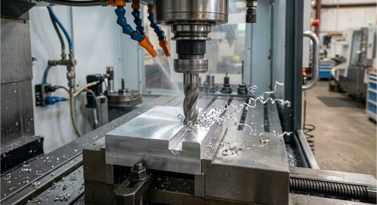
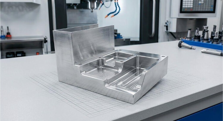
Aluminum milling is a machining process that removes material from an aluminum workpiece with a rotating cutting tool. Manufacturers use it to create flat surfaces, slots, pockets, contours, holes, and other controlled features that require greater accuracy than simple cutting methods can provide.
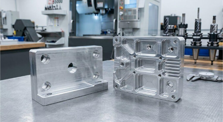
In real production, manufacturers often use aluminum milling for machined plates, custom brackets, housings, support blocks, covers, and prototype parts that need accurate dimensions or more complex shapes. This process is especially useful when a project still needs design changes, tighter feature control, or a fast path from a CAD model to a finished part.
Compared with tooling-based processes, milling gives teams more control in the early stage of a project. It is often a better choice when a part needs true-position control on machined holes, flat reference surfaces, controlled pocket depth, or clean sealing and mating faces. This is especially true in prototype, bridge-production, and low- to mid-volume work.
Why Aluminum Is Commonly Used for Milling?
Aluminum is commonly used for milling because it offers good machinability, light weight, corrosion resistance, and wide availability. For many parts, it gives manufacturers a practical way to machine detailed features quickly while keeping the finished part much lighter than a steel version.
Why is aluminum easier to machine than many metals?
Many aluminum alloys cut with less resistance than common steels. This behavior often allows higher cutting speeds, better chip formation, and lower spindle load when the tool geometry matches aluminum.
That is why many production shops run aluminum machining on 10,000 RPM or higher spindle platforms when they want faster material removal. In practice, this makes aluminum a strong choice for brackets, housings, machined plates, and other parts that need both speed and accuracy.
Why is aluminum still difficult to control?
Easy cutting does not remove the need for process control. Aluminum reacts quickly to poor chip removal, weak tool edge condition, or an unstable setup. When these problems appear, built-up edge, burrs, surface marks, and part movement become much more likely.
This issue becomes more obvious on thin-wall housings, cosmetic covers, sealing surfaces, and parts that will later be anodized. A wall thickness that looks acceptable in CAD can still move under cutting force if the support is weak. In many aluminum jobs, the real problem is not cutting speed. The real problem is that chips do not cleanly leave the cut.
Which aluminum grades are often milled?
Several aluminum grades are commonly used for milling, but they do not behave the same way in production. Alloy choice affects part performance, chip behavior, burr tendency, surface finish stability, and cost.
6061 is one of the most widely used grades because it offers a balanced mix of machinability, strength, corrosion resistance, and availability. Manufacturers often choose 7075 when a part needs higher strength, especially for more heavily loaded structural parts.
Typical material data show that 6061-T6 has an ultimate tensile strength of about 310 MPa, while 7075-T6 has an ultimate tensile strength of about 572 MPa. This difference helps explain why 7075 is more often used for higher-load applications, while 6061 remains the more common all-around choice.
What Affects Aluminum Milling Performance?
Good aluminum milling results depend on more than one setting or tool choice. The sections below show which variables most strongly affect stability, finish, and repeatability.
Material grade
Material grade affects much more than final part strength. It also affects cutting resistance, chip shape, burr tendency, surface response, and overall machining stability.
For example, softer aluminum can often be machined at much higher cutting speeds, while harder aluminum alloys usually require a narrower, more controlled range. In practice, some aluminum milling conditions may run at about 100 to 500 m/min, while harder alloys may stay closer to 100 to 200 m/min. This difference is one reason the same cutting approach does not always work well across different alloys.
Tool geometry
Tool geometry directly affects chip flow, cutting force, heat, and surface finish. In aluminum milling, sharp cutting edges and polished flute surfaces often work better than more general-purpose tool shapes made for many materials.
If the tool geometry is not suited to aluminum, chips are more likely to smear, stick, or build up on the cutting edge. This can quickly reduce surface quality and make the process less stable. This problem becomes more obvious on pockets, thin walls, sealing faces, and visible machined surfaces.
Speed and feed
Speed and feed directly affect chip load, heat, tool life, and finish quality. If the speed is too low, the tool may rub rather than cut cleanly. If the feed is too aggressive for the setup, vibration, burrs, or part movement may appear.
In many aluminum jobs, spindle speed can run much higher than in steel machining, but high speed alone does not create a stable process. In high-speed milling, spindle speed may reach 20,000 rpm or more, while radial engagement is often kept below about 25% of cutter diameter. This shows that stable aluminum milling depends not only on speed, but also on engagement control and toolpath planning.
Coolant and chip removal
Chip control is one of the most overlooked parts of aluminum milling. In many cases, the real problem is not that aluminum is hard to cut. The real problem is that chips do not cleanly leave the cut.
When chips remain in the cutting area, they can be cut again, damaging the surface, raising local heat, and increasing the risk of built-up edge. On deeper pockets and narrower features, this risk rises quickly. Good coolant delivery, air blast, or another effective chip-clearing method often has a strong effect on both surface finish and process stability.
Common Problems in Aluminum Milling
Aluminum can be machined quickly, but problems also show up quickly when conditions are wrong. The following sections break down the most common issues and the causes that usually drive them.
Built-up edge
Built-up edge happens when aluminum sticks to the cutting edge during machining. Once material starts building on the tool, the real edge shape changes, and the cutter no longer cuts the part as intended.
This often leads to poorer surface finish and weaker size control. This problem is more likely to occur when the cutting edge is not sharp enough, the cutting speed is too low for the setup, or chips do not clear the cut well.
Poor surface finish
Poor surface finish in aluminum milling is often linked to tool wear, vibration, chip recutting, or weak setup conditions. Even when the material itself cuts easily, the surface can still come out rough, smeared, or uneven if the process is unstable.
As a practical benchmark, a standard as-machined CNC finish is often around Ra 3.2 μm, while an added finishing pass may improve that to about Ra 1.6, 0.8, or even 0.4 μm. That is why surface instability matters more on cosmetic covers, sealing surfaces, and parts that will later be anodized.
Burr formation
Burrs are common in aluminum milling because the material can deform at the edges rather than break cleanly. Burr size usually increases when the tool becomes dull, when the edge lacks support, or when the cutting path does not fit the feature well.
This problem is often more obvious on thin edges, slot exits, smaller holes, and lighter wall sections. Burrs increase deburring time but can also affect assembly fit, handling safety, and the final appearance if not controlled early.
Chatter and vibration
Chatter usually appears when cutting force, tool stability, and setup rigidity are out of balance. It can leave visible marks on the surface, shorten tool life, and reduce dimensional control reliability.
This risk increases when tool reach is too long, part support is too weak, or cutting data is too aggressive for the geometry. Thin parts, deep cavities, and narrow features are especially sensitive because they leave less room for process instability.
Tool Selection for Better Aluminum Milling
The right tool can improve finish, chip control, and overall stability. The sections below explain which tool features matter most and why they affect results.
End mill material
Carbide end mills are widely used for aluminum milling because they offer good rigidity, wear resistance, and stable cutting performance. For many jobs, they provide a practical balance between tool life and machining efficiency.
However, the tool material still needs to match the job. A simple prototype bracket does not place the same demands on the cutter as a longer production run with deeper cavities or tighter surface finish needs. In most cases, the better choice is the one that best fits the part’s actual cutting load, feature depth, and stability target.
Flute count
Flute count affects both chip space and cutting behavior. In aluminum milling, lower flute counts are often preferred because they leave more room for chips to clear from the cut. In many shops, 2-flute and 3-flute end mills are common choices for aluminum, as they are for this reason.
This matters even more in deeper pockets, slots, and smaller internal features where chip packing can happen quickly. If the flute count is too high for the feature and chip load, the risk of recutting rises. Surface finish can drop, and the built-up edge becomes easier to trigger.
Coating choice
Coating can help in aluminum milling, but it cannot fix a weak process. Some coatings are used to reduce sticking and improve chip flow across the tool surface. This can help the cutter stay cleaner during the cut.
At the same time, the coating choice should support the material rather than introduce extra friction. In practice, real cutting performance matters more than coating claims. A cutter that runs cleanly in the real part geometry is more useful than a coating description that sounds strong but does not improve the cut.
Edge sharpness
Edge sharpness is one of the most important tool features in aluminum milling. A sharp edge helps the cutter shear the material cleanly instead of pushing, smearing, or tearing it.
Once the edge starts to lose sharpness, the process can decline quickly. Built-up edges, heavier burrs, and a weaker surface finish often appear first on thin walls, sealing faces, cosmetic surfaces, and smaller features, where cut quality is more readily apparent.
Design Tips for Aluminum Milling
Many machining problems begin in the part design, not on the machine. The sections below highlight design choices that can improve manufacturability and control cost.
Wall thickness
Thin walls are one of the most common causes of instability in aluminum milling. As the wall becomes thinner, the cutting force can push or vibrate the material more easily during machining.
As a practical guide, very thin features often become much harder to control once wall thickness drops below about 1 to 1.5 mm, especially on taller walls or unsupported sections. On housings, covers, and lighter structural parts, a wall that looks acceptable on screen may still move during cutting if the real setup does not support it well enough.
Corner radius
The inside corner radius affects both tool access and cutting stability. Very tight internal corners usually require smaller tools, and smaller tools often remove material more slowly with lower rigidity.
This can increase cycle time and make chatter or tool deflection more likely. If a sharp inside corner is not necessary for function, a larger practical radius usually makes the part easier to machine and easier to quote. In many jobs, even a small increase in radius allows a larger cutter and a much more stable process.
Pocket depth
Deep pockets are harder to machine than open and shallow features. As pocket depth increases, tool reach usually increases as well, and longer reach reduces stiffness.
As a practical benchmark, machining risk often rises sharply once the pocket depth exceeds about 3 to 4 times the tool diameter. This increases the chance of chatter, unstable surface finish, and dimensional variation. A pocket may look simple in the drawing, but once the depth is large compared with the tool diameter, both chip removal and tool stability become harder to control.
Tolerance control
Tight tolerances should be used where they add real value, not across the whole part by default. Overly tight tolerance demands often increase machining time, inspection effort, and process difficulty without improving function.
A better approach is to maintain tighter control over critical holes, sealing faces, assembly interfaces, and datum-related features, while applying more practical limits on secondary areas. For example, holding ±0.05 mm on selected critical features is very different from pushing large areas of the part toward ±0.01 mm by default. This usually gives a better balance between performance, manufacturability, and cost.
Surface finish requirements
Surface finish expectations should align with the part’s intended use. A visible cover, sealing face, or mating surface may need closer control, while internal or non-critical faces may not need the same finish level.
As a rough reference, many standard machined aluminum parts are acceptable at around Ra 3.2 μm, while cosmetic or sealing-related surfaces may need a finer finish. If the finish requirements are not clear, the machining plan often becomes less efficient. Extra passes, slower cutting, or unnecessary tool changes may be added to areas that do not gain real benefit from them.
Conclusion
Aluminum milling works well when the process fits the part. Material choice matters, but it does not determine the result on its own. Stable quality depends on how well the alloy, cutter, toolpath, chip control, setup, and part design work together under real machining conditions.
Our team supports aluminum milling projects from prototype to production. We can review your part geometry, material choice, tolerance requirements, and surface finish needs before quoting, so you can spot machining risks earlier and avoid unnecessary cost.
Whether you are working on housings, brackets, plates, covers, or other custom-machined components, we can help you evaluate a practical manufacturing approach based on your drawings and project goals. Send us your CAD files or project details to receive engineering feedback, a lead-time review, and a quotation for your aluminum milling project.