
Blind holes are common in machined parts, but they often create more trouble than their size suggests. In production, a small blind hole can affect chip evacuation, usable thread length, bottom clearance, and first-piece approval.
That is why blind holes should be defined early, not corrected on the shop floor later. If depth, bottom shape, and thread requirement are unclear, the result is often short thread engagement, broken taps, slower cycles, or avoidable rework.
This guide focuses on the points that matter most in production. It explains what a blind hole is, when to use it, and why it usually needs more control than a through hole.

What Is a Blind Hole?
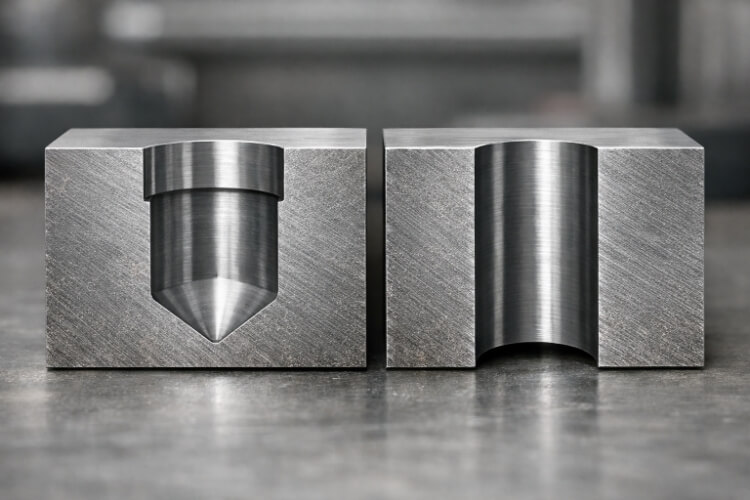
A blind hole is a hole that goes into a part but does not pass through the full thickness. It stops at a controlled depth and has a closed bottom. Unlike a through hole, it does not open on the opposite side of the part.
A blind hole differs in that the specified depth must support the feature’s actual function, not just match the number shown on the drawing. The hole must provide sufficient usable depth while keeping the far side of the part closed.
In real machining, a standard drill usually does not create a flat bottom. It leaves an angled bottom because of the drill point geometry. Common point angles, such as 118° and 135°, mean that the bottom part of the hole is not fully usable as straight-wall depth.
Blind holes are often used when the back side of the part must remain closed. This is common in enclosures, covers, mounting points, and threaded features. Designers may choose a blind hole to protect the outer surface, keep a wall sealed, or create internal fastening without breaking through the opposite face.
Blind hole vs through hole
At a basic level, the difference is simple. A through hole passes completely through the part, while a blind hole stops inside the material and leaves a closed bottom.
From a manufacturing standpoint, that difference matters more than it may seem on the drawing. Through holes are usually easier to machine because chips can exit more freely, coolant can reach the cutting zone more easily, and the tool does not need to stop at a fixed internal depth.
Blind holes require more control. The closed bottom makes chip evacuation harder, increases the risk of trapped heat, and leaves less room for drilling and tapping errors. In threaded features, that difference becomes even more important because the hole has to provide both usable thread engagement and enough clearance below the thread.
The right choice depends on function. If the part needs a sealed wall, a protected outer face, or a controlled internal stop, a blind hole may be the better option. If those conditions do not apply, a through hole is often the simpler, lower-risk choice for machining, tapping, and inspection.
When to Use a Blind Hole?
A blind hole should be used only when a closed bottom serves a clear function. In most cases, that means sealing, controlled insertion depth, a protected outer surface, or internal fastening without breakthrough.
When must the back side stay closed?
A blind hole is often the right choice when the far side of the part must stay unbroken. This is common in covers, housings, sealed walls, and visible outer faces where a through hole would create a leak path, weaken the wall, or leave an unwanted opening.
In these cases, a blind hole allows the design to keep the outer wall intact while still providing a mounting or threaded feature. When the back face serves to seal, protect, or enhance appearance, a blind hole is usually justified.
When does the design need a fixed depth?
A blind hole also makes sense when the feature must stop at a controlled depth. This is common when a fastener, locating pin, or mating part should engage only to a set distance inside the component.
Here, the hole depth is part of the function. The bottom of the hole helps control fit, alignment, or assembly stop position in a way that a through hole cannot.
This matters even more in threaded holes, where the required engagement is not arbitrary. A common rule of thumb is about 1× the nominal thread engagement diameter in steel and about 2× in aluminum. In aluminum blind holes, usable depth is consumed faster than many drawings expect.
When does sealing or appearance matter?
Some parts use blind holes because the outer surface must remain closed and clean. This may be for sealing, corrosion resistance, electrical isolation, or to prevent the outer face from showing an opening or an exposed fastener end.
In these cases, the blind hole supports both function and appearance. If a breakthrough would damage sealing, surface quality, or the finished look of the part, a blind hole is usually the better choice.
Why Blind Holes Are Harder to Machine?
Blind holes create machining limits that through holes do not. The sections below explain where chip control, heat, depth, and tapping usually become more difficult.
Chips are harder to clear
Chip evacuation is one of the main reasons blind holes are more difficult to machine. As the drill goes deeper, chips have less room to break, move, and leave the hole.
In a through hole, chips can usually move forward and exit the cut more easily. In a blind hole, they tend to stay trapped near the bottom for longer. That can lead to recutting, rougher surfaces, higher cutting load, and faster tool wear.
A useful shop rule is that peck drilling often becomes more necessary once hole depth exceeds about 3–4 times the drill diameter. At that point, chip evacuation often becomes the main process limit.
Heat is harder to control
Heat is also harder to manage in a blind hole because cutting occurs in a more enclosed space. The deeper the tool penetrates the feature, the harder it becomes for heat to escape the cut.
This matters because excess heat shortens tool life and increases variation across repeated holes. Once the chip flow is already weak, trapped heat usually makes the process less stable.
That is why blind holes usually need more careful control of feed, speed, coolant access, and drilling cycle than a similar through hole.
Depth is easier to get wrong
A blind hole depends on depth control, so the tool must stop at the right point every time. That creates another source of risk.
The hole must be deep enough to meet the functional requirement, but not so deep that it weakens the remaining wall or breaks through the far side. This becomes more sensitive when the part has thin sections, multiple blind-hole depths, or a tapped section near the bottom.
The hole bottom also adds complexity. Because standard drills leave an angled bottom, the last part of the hole is not fully usable as straight-wall depth. If the drawing ignores that, the hole may meet nominal depth and still fail in assembly.
Tapping is more likely to fail
Blind-hole tapping is often one of the highest-risk steps in the whole process. The tap is cutting threads in a closed-bottom hole, so it has less room for chips and less room for error.
If the drilled hole does not leave enough clearance below the required full thread, the tap can reach the bottom too soon. Once chips compact near the bottom, cutting torque rises quickly, and broken taps become much more likely.
Even when the tap does not break, the thread can still be poor. The usable thread may end up short, rough near the bottom, or partly blocked by chips. A blind-threaded hole can appear complete yet still fail in assembly.
How to Design a Blind Hole?
A good blind hole starts with a design that matches the real process. These points show how depth, bottom shape, and nearby geometry affect manufacturability.
Total depth and usable depth
One of the most common design mistakes is treating all drilled depths as equally usable. In practice, total drill depth and usable functional depth are often different.
Total depth is the distance the tool extends into the part. Usable depth is the portion that actually supports the function, such as thread engagement, pin insertion, or clearance for a mating feature.
A stronger design defines the functional depth first, then leaves enough extra drilled depth for the process to create that result safely. In small tapped holes, even a modest loss of usable depth can reduce actual engagement.
Hole depth and thread depth
In threaded blind holes, hole depth and thread depth should not be treated as the same value. The drilled hole usually needs to go deeper than the required full thread.
This extra space gives the tap room room to run near the bottom and gives chips somewhere to go instead of packing into the thread zone. If the drawing shows only one depth, the shop may have to guess whether that number means total drilled depth or usable thread depth.
This is also where real engagement matters. A common rule of thumb is about 1× nominal diameter of engagement in steel and about 2× nominal diameter in aluminum. That makes blind-hole depth planning especially important in aluminum parts, where thread length requirements can grow quickly.
Why is the bottom of the hole not flat?
A standard drill usually creates a conical bottom, not a flat one. This has a direct effect on blind-hole function.
If the feature depends on a flat seating surface or full-depth contact at the bottom, a standard drilled hole may not be enough. The bottom shape can reduce usable depth, change how a mating part seats, or limit the truly effective thread zone.
Do not imply a flat bottom unless the part actually needs one. When a flat bottom is function-critical, that usually means a second operation is needed after drilling.
How do depth and diameter affect stability?
Depth and diameter work together in a blind hole. As the hole gets deeper relative to its diameter, the process usually becomes less stable and more sensitive to chip evacuation, heat, and tool behavior.
A shallow, larger-diameter blind hole is generally easier to run than a deep, narrow one. Smaller drills are less rigid, deeper cuts make chip evacuation harder, and coolant access becomes more limited as depth increases.
How Blind Holes Are Machined and Tapped?
Blind holes are usually made in stages. The hole is drilled first, then finished further if the design needs a flatter bottom or a threaded section.
Drilling a standard blind hole
A standard blind hole is usually drilled to a controlled depth. Unlike a through hole, the tool cannot run out the other side, so the drilled depth has to support both the feature’s function and the geometry left by the drill point.
Standard drilling defines the hole body, not the final usable bottom condition. If the feature later needs full-thread engagement near the bottom or a flat seating surface, the first drilling step must leave room for the next operation.
When is peck drilling used?
Peck drilling is used when chip packing becomes a real process limit. Instead of drilling the full depth in a single continuous feed, the tool advances in steps and retracts between cuts, allowing chips to break and clear more easily.
This becomes more useful as depth increases, especially once the hole moves beyond about 3–4× drill diameter. At that point, chip evacuation often becomes the main problem rather than the nominal hole size.
Peck drilling adds cycle time, but it is often cheaper than dealing with recutting, heat buildup, poor finish, or trouble in the next step.
When is a flat-bottom hole needed?
A standard drill does not produce a flat bottom. It leaves a conical bottom that follows the drill point geometry.
If the feature needs a seating face, a precise depth stop, or a more usable bottom area, drilling alone may not be enough. In that case, a second operation is usually needed after drilling.
The key question is simple: Does the part actually need a flat bottom for function, or is the drawing only implying one by habit? If a function does not demand it, adding a flat-bottom step usually adds cost and time without adding much value.
Choosing the right tap or thread milling method
The threading method should match the hole, the material, and the part’s risk level. In blind holes, chip control matters more, so tap choice matters more, too.
For many blind-threaded holes, a spiral flute tap is a practical choice because it helps pull chips upward rather than forcing them deeper into the hole. When the feature is high risk, thread milling is often the safer method.
Thread milling is slower in some cases, but it gives better control when thread quality is critical or when a broken tap would be expensive to recover from. The better method is not always the fastest one. It is the one that gives stable results across the batch.
How to Inspect a Blind Hole?
A blind hole is only useful if the finished feature actually works in assembly. The checks below focus on function, not only on nominal dimensions.
Checking hole depth
Hole depth is one of the first things to confirm in a blind hole. Because the feature stops inside the part, even a small shortfall can reduce fastener engagement, limit pin insertion, or remove the bottom clearance needed for tapping.
The main inspection mistake is checking only the deepest point left by the drill tip. In a blind hole, that value is not always the same as usable functional depth, because the drill leaves an angled bottom rather than a full straight-wall section.
A good inspection method checks the depth that actually matters to the part. In a threaded blind hole, that usually means confirming that the drilled depth and remaining bottom clearance both support the required usable thread.
Checking thread quality
For threaded blind holes, thread quality is just as important as hole depth. A thread can look acceptable and still fail in assembly if usable engagement is shorter than the design requires or if chips have damaged the thread near the bottom.
This is where real engagement matters. A common rule of thumb is about 1× the nominal engagement diameter in steel and about 2× in aluminum, though softer materials or higher-load joints may require more.
Inspection should confirm not only that threads exist, but that the usable thread length supports the joint. In blind threaded holes, that is the difference between a thread that looks complete and one that actually works.
What first-piece inspection should confirm?
First-piece inspection is especially valuable for blind holes because blind-hole problems often repeat once the cycle is set. If the first part already shows shallow depth, short engagement, or poor chip control, the same issue can continue across the batch.
For a blind hole, the first-piece inspection should confirm the drilled depth, the thread condition if the hole is tapped, and the remaining clearance below the usable thread. Those checks show whether the process is producing a functional hole or only a nominal one.

How to Show a Blind Hole on a Drawing?
A blind hole can be machined correctly only if the drawing is clear. The following points show what the callout should communicate to avoid shop errors.
What should the drawing include?
A blind hole callout should include the information needed to correctly make and check the feature. At a minimum, that usually means hole size, total drill depth, and whether the hole is plain or threaded.

Hole depth vs thread depth
Hole depth and thread depth should not be treated as the same value unless the process and function truly make them the same. In most blind-threaded holes, the drilled hole must extend deeper than the required full thread.
This is also where real engagement matters. A common rule of thumb is about 1× nominal diameter of engagement in steel and about 2× nominal diameter in aluminum.
What should a clear callout show?
A clear blind-hole callout should tell the shop what must be controlled and what does not need unnecessary precision. For a plain blind hole, that usually means diameter and total required depth.
For a threaded blind hole, this usually means the thread specification, the required effective thread depth, the supporting drill depth, and any bottom condition that affects function. A clear callout should indicate which depth controls function and which depth supports only the process.
Conclusion
Blind holes look simple, but they need more control than many other hole features. Because the hole stops within the part, it affects design, drilling, tapping, inspection, and drawing clarity.
That is why a blind hole should be a functional decision, not a default one. When the design needs a closed back side, a controlled insertion depth, or a clean outer face, a blind hole can be the right answer.
Need help with blind holes, threaded features, or machining-ready part design? Send us your drawings or project requirements, and our engineering team will review the feature, identify machining risks early, and provide practical feedback for production, cost, and lead time.
FAQs
Why are blind holes harder to machine?
Blind holes are harder to machine because the tool must cut into a confined space. Chip evacuation, heat control, bottom clearance, and depth accuracy all become more sensitive.
How much extra depth does a blind tapped hole need?
The drilled hole usually needs to go deeper than the required full thread. A practical rule is to leave about 0.5× hole diameter as unthreaded space at the bottom so the tap has room to run and chips have room to collect.
Why do taps break in blind holes?
Taps often break in blind holes because chips compact near the bottom, the drilled hole is too shallow, or the bottom clearance is not enough. Once torque rises, failure can happen quickly, and recovery can be expensive.
When should a blind hole be changed to a through hole?
A blind hole should be reconsidered when the part does not truly need a closed bottom. If a through hole can meet the same function, it is often the easier and lower-risk option.