Welding defects directly impact a project’s bottom line. When a weld fails to meet specifications, it forces rework, scraps expensive materials, and creates bottlenecks in downstream assembly.
This guide categorizes the nine most common welding defects into two groups: internal structural failures and external dimensional flaws.
This article focuses on what is behind common welding defects. It also explains what teams can do in daily production to prevent them. The aim is to lower defect rates and keep orders moving.
Why Welding Defects Still Happen in Production?
In a high-volume manufacturing environment, consistent weld quality requires strict control over multiple variables. Most defects occur when there is unmanaged variation in heat input, upstream part fit-up, or joint cleanliness.
Heat input and travel speed
Heat input controls penetration depth and cooling rates. If amperage is too high or travel speed is too slow, the excess heat causes severe burn-through or part distortion.
This is a critical failure point when TIG welding heat-sensitive materials like 16-gauge (1.5mm) stainless steel or 5052 aluminum enclosures. Conversely, low heat input results in cold welds and a lack of fusion, directly compromising the structural load capacity of the joint.
Joint preparation and fit-up
Weld quality is often determined at the laser cutter. If your upstream laser cutting is off by 0.5mm, or the press brake operator misses the bending tolerance, the welder is forced to bridge uneven gaps.
Attempting to weld misaligned edges drastically increases the chance of incomplete penetration and traps residual stress. Reliable welding requires holding strict, repeatable tolerances in the blanking and forming stages so the joint fits perfectly every time.
Surface contamination
Sheet metal entering the welding station often carries laser oxide edges, rust, cutting fluids, or drawing compounds. When exposed to the welding arc, these contaminants vaporize and get trapped in the molten pool.
This chemical reaction is the primary cause of internal porosity. Implementing a strict pre-weld cleaning protocol—such as mechanically grinding laser oxide layers or wiping joints with specified solvents—is mandatory for maintaining structural integrity.
Shielding gas and consumables
Shielding gas displaces atmospheric oxygen to protect the molten puddle. If the gas flow rate is incorrect, or if shop drafts blow the argon mixture away, the weld will immediately develop porosity.
Consumable management is equally critical. Using improper filler alloys or failing to store low-hydrogen electrodes in a temperature-controlled oven introduces moisture into the weld, which often causes delayed cracking after the part has cooled.
Welding technique and consistency
Torch angle, arc length, and travel speed dictate how the filler metal ties into the base material. Inconsistent manual techniques create uneven bead profiles, undercut along the edges, and heavy spatter.
These are not just visual issues. Excessive spatter forces an extra 15 to 20 minutes of manual grinding per part, which drives up unit costs and delays the part from moving into the powder-coating or plating stages.
Structural and Internal Welding Defects
Structural defects compromise the mechanical strength, load capacity, and fatigue life of a part. Because these flaws often hide beneath the surface, they are insidious. Discovering a cracked joint during ultrasonic testing (UT) is bad; having a part fail in the field under dynamic load is catastrophic.
#1 Porosity
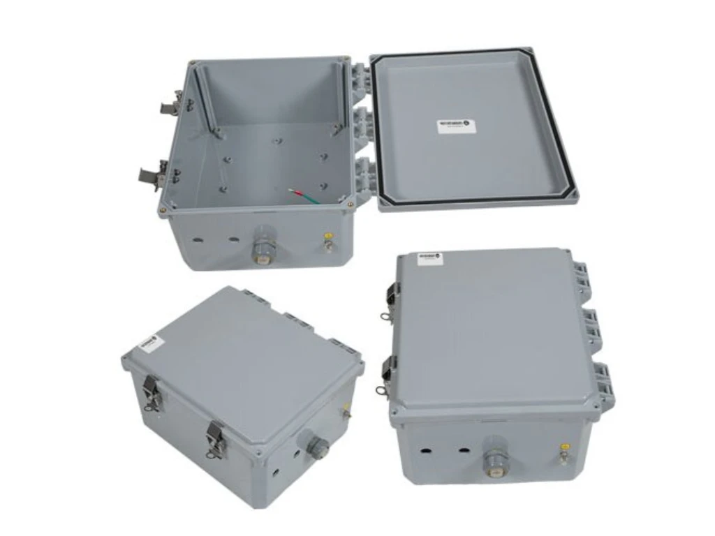
Porosity appears as spongy, spherical gas pockets trapped within the solidified weld. In precision sheet metal enclosures, micro-porosity is not just a strength issue—it guarantees a failed IP67 water-tight test, rendering outdoor electronic housings useless.
This defect occurs when atmospheric gases contaminate the molten puddle. A primary driver in sheet metal fabrication is TIG welding directly over laser-cut oxide edges or failing to remove drawing compounds.
Prevention requires strict shop discipline, not just welder skill. Operators must mechanically grind laser edges or chemically clean joints before striking an arc. In production, shielding gas (typically Argon) must be strictly calibrated—usually between 15 to 20 CFH—and shop drafts must be managed to maintain gas coverage.
#2 Incomplete Penetration and Lack of Fusion
Incomplete penetration means the weld fails to fill the joint root. Lack of fusion (cold lap) occurs when filler metal flows but does not melt into the base material’s sidewall. Under vibration or heavy dynamic loads, these unfused areas act as fracture initiation points, leading to sudden structural failure.
While often blamed on low amperage or fast travel speeds, the root cause usually lies upstream. If a CNC press brake bends a 1/4″ (6mm) A36 steel bracket with a root gap that is too tight, the arc physically cannot reach the bottom of the joint.
To prevent this, manufacturing engineering must specify the exact bevel angles and root openings based on material thickness. On the floor, strict first-article inspection (FAI) ensures the upstream bending tolerances are held, giving the welder the exact joint geometry needed to achieve full penetration.
#3 Cracking
Cracking is the most severe structural failure, rendering a part immediate scrap. Hot cracking occurs right as the weld pool solidifies. Cold cracking (hydrogen-induced cracking) is a delayed reaction that can appear days later, often causing catastrophic failure after the product has shipped.
Hot cracking is typically caused by rigid fixturing that prevents the metal from contracting naturally. Cold cracking primarily affects high-strength steels and is caused by moisture introducing hydrogen into the metal’s grain structure.
Preventing cracks in mass production requires strict thermal and consumable management. Low-hydrogen electrodes (like E7018) must be stored in heated rod ovens to eliminate moisture. For thicker structural components, mandatory pre-heating and post-weld heat treatment (PWHT) slow the cooling rate, allowing trapped hydrogen to escape and relieving residual stress.
#4 Slag Inclusion
Slag inclusions are non-metallic solid particles trapped inside the weld. This is specific to flux-based processes like FCAW (Flux-Cored) or SMAW (Stick) used on heavy structural frames. These glassy pockets create internal weak spots that will cause an entire batch of parts to fail X-ray or UT inspection.
Inclusions almost exclusively happen during multi-pass welding when an operator fails to completely chip and wire-brush the slag layer from the previous pass before laying the next one.
Preventing this requires standardizing the inter-pass cleaning protocol. Operators must aggressively clean the weld valley with a grinder or wire wheel between every single pass. Maintaining a proper torch angle also forces the slag to stay behind the puddle, preventing it from rolling forward and being buried.
Surface and Dimensional Welding Defects
Surface defects may not instantly snap under load, but they destroy unit economics. They damage cosmetic appearance, pull parts out of dimensional tolerance, and force hours of unplanned manual grinding.
#5 Undercut
Undercutting melts a groove into the base metal along the toes of the weld without filling it back in. This creates a mechanical notch—a classic stress riser where fatigue fractures initiate. Cosmetically, it looks terrible and requires heavy filling before powder coating.
This defect is typically driven by running amperage too high or using an aggressive weaving technique, which is especially detrimental on thin-gauge stainless steel.
Operators must dial back the heat input. More importantly, they need to adjust their technique by pausing for a fraction of a second at the edges of the weave. This allows the filler metal to catch up and fill the melted groove flush with the base material.
#6 Spatter
Spatter consists of molten metal BBs that fuse to the surrounding metal. While standard in some processes, excessive spatter in MIG welding signals an out-of-control arc. It ruins mating surfaces and threads. If an operator spends an extra 15 minutes per part grinding spatter off a chassis, your production costs multiply rapidly.
Heavy spatter usually points to a mismatch between voltage and wire feed speed, or using the wrong shielding gas mixture (such as 100% CO2 when an Argon mix is required).
Fine-tuning the machine parameters or switching to pulsed MIG capabilities will eliminate the vast majority of spatter. Relying purely on anti-spatter spray is a band-aid; fixing the arc characteristics is the actual production solution.
#7 Burn-Through
Burn-through happens when the arc melts a hole completely through the part. This is the primary enemy of sheet metal fabrication. When welding heat-sensitive materials like 18-gauge 304 stainless or 5052 aluminum panels, the thin metal cannot dissipate the heat fast enough.
Moving the torch too slowly or using a standard continuous arc transfers too much thermal energy into one spot, immediately ruining the workpiece.
Preventing burn-through requires specific tooling and advanced machine settings. Using pulsed TIG allows the arc to rapidly alternate between high and low current, significantly lowering the overall heat input. Additionally, clamping custom copper backing bars behind the joint acts as a heatsink, pulling heat away while physically supporting the puddle.
#8 Distortion
Distortion occurs when localized heat from the welding arc causes the metal to expand rapidly, followed by uneven contraction during cooling. This thermal stress twists the part completely out of its dimensional tolerances.
In sheet metal fabrication, distortion is an assembly killer. A chassis that warps by even 1.5mm will not align with its mating components, forcing costly manual straightening or outright scrapping of the part.
While skilled operators can manage distortion on a single prototype using skip welding and strategic tacking, mass production requires a different approach. Stable production depends on heavy, custom CNC fixtures. These fixtures hold the part in position until it fully cools. This helps keep later parts consistent with the approved first article.
#9 Overlap
Overlap (often called a cold roll) happens when molten filler metal flows over the cold base material without actually melting and fusing to it. It leaves a rounded blob sitting on top of the joint that fails visual inspection and peels off under stress.
This is almost always caused by a travel speed that is too slow. If the operator lingers, the weld puddle grows too large and rolls ahead of the arc. The arc ends up melting the filler wire onto cold steel rather than melting the base metal itself.
Correcting overlap is straightforward: the operator must increase travel speed and maintain a torch angle that directs the arc specifically at the leading edge of the puddle.
How to Inspect Welds Before Parts Leave the Shop?
Inspection is not simply about spotting ugly welds; it is a critical risk-management tool. Finding a defect while the part is still on the welding table is a cheap fix.
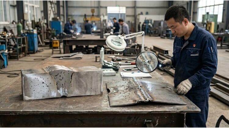
Visual inspection
Visual testing is the first and most cost-effective line of defense. Certified inspectors use specialized gauges to measure fillet sizes and verify that no surface defects are present.
If a weld fails visual inspection, it is immediately rejected. Catching undercut or spatter here prevents a flawed part from moving into costly secondary machining or finishing stages.
Dye penetrant testing
Dye penetrant is highly effective for finding surface-breaking defects on non-porous materials like 304 stainless steel or 6061 aluminum. A highly visible dye is applied to seep into micro-cracks.
By making PT standard for watertight enclosures, a reliable manufacturing partner catches micro-porosity before the parts ship. This directly protects you from expensive field failures.
Magnetic particle testing
For ferromagnetic materials like standard carbon steel frames, magnetic particle testing is the standard. An electromagnetic yoke induces a magnetic field, and iron particles are dusted over the weld.
Any surface or subsurface cracks disrupt this field, pulling the iron particles into a visible line. This method is an excellent safeguard to detect early-stage fatigue cracks on structural load-bearing components.
Ultrasonic and radiographic testing
When internal soundness is non-negotiable—such as in heavy load-bearing chassis—volumetric testing is required. Ultrasonic Testing (UT) uses high-frequency sound waves to bounce off internal voids.
Radiographic Testing (RT) uses X-rays to capture a literal picture of the weld’s internal structure. Both methods definitively prove the absence of internal defects without destroying the expensive workpiece.
How Part Preparation Affects Weld Quality?
Weld quality is not determined entirely by the person holding the torch. A welder is only as good as the machined parts they are given to assemble.
Laser cutting and edge quality
When sheet metal is cut using assist gases, it leaves a microscopic oxide layer or dross on the cut edge. Attempting to TIG weld directly over this edge causes immediate internal porosity.
High-quality welding requires dialing in the CNC laser to produce a dross-free kerf. A strict pre-weld mechanical edge cleaning protocol must also be enforced to ensure structural integrity.
Fit-up accuracy and root gap control
Consistent welds require consistent joint geometry. If the root gap on a joint varies from 1mm to 3mm across a batch, the required heat input changes drastically.
Maintaining tight machining tolerances in the blanking stage ensures a repeatable root gap. This prevents the welder from compensating with excess heat, directly avoiding burn-through and severe distortion.
Bending accuracy and residual stress
If a press brake bends a bracket to 88 degrees instead of 90 degrees, the welder must physically force the part into alignment. This drives massive residual mechanical stress into the joint.
Once the clamps are released after welding, that trapped stress reacts violently. It will either pull the assembled part completely out of dimensional tolerance or immediately cause a cold crack.
Fixturing and part restraint
Relying on manual clamps works for a single prototype, but transitioning to mass manufacturing requires heavy, modular CNC fixturing. Thermal expansion during welding is fast and unpredictable.
To keep tight geometric tolerances across a 1,000-piece run, the part needs rigid fixturing. The fixture holds the part in position during welding and helps control heat. This reduces movement and lowers the risk of warping.
How to Reduce Welding Defects in Repeat Production?
Transitioning from a single prototype to mass manufacturing requires a fundamental shift in quality control. Defect prevention is no longer just about individual welder skill; it relies on rigid, repeatable production systems.
WPS control and parameter windows
A Welding Procedure Specification (WPS) acts as the strict engineering blueprint for every joint. It dictates the exact voltage, wire feed speed, and travel speed required for consistent penetration.
Relying on operators to “dial it in by feel” guarantees high defect rates across multiple shifts. Strict WPS control confines operators within a narrow parameter window, preventing unauthorized adjustments that ruin mass production runs.
First-piece approval
Before a full production run begins, the first assembled unit must undergo a rigorous First Article Inspection (FAI). This critical step validates the CNC fixturing, upstream machining tolerances, and actual weld penetration.
Only after quality control signs off on this physical proof does the mass batch proceed. This protocol prevents a minor setup error from systematically ruining hundreds of expensive sheet metal components.
In-process inspection points
Relying entirely on end-of-line inspection creates massive bottlenecks and traps defective parts deep in the production cycle. High-volume manufacturing requires strategic quality hold points directly on the shop floor.
Implementing hourly visual checks or sample weld-sectioning ensures the welding parameters have not drifted. Catching a shielding gas issue early saves an entire shift’s worth of production from the scrap bin.
Repair limits and traceability
Not all defects can or should be repaired. Repeatedly grinding and re-welding the same joint alters the metallurgical structure, causing localized brittleness and expanding the heat-affected zone (HAZ).
Establishing strict repair limits prevents operators from endlessly chasing defects to save a scrapped part. Coupling this with batch traceability allows engineers to quickly isolate root causes, protecting your overall supply chain reliability.
Welder training and standard work
Skilled welders are critical, but high-volume production demands strict Standard Operating Procedures (SOPs). The goal is to remove the variability of individual techniques and replace it with repeatable science.
Standardizing torch angles and inter-pass cleaning methods across all operators ensures completely uniform bead profiles. This consistency guarantees that downstream finishing, powder coating, and final assembly remain highly predictable.
Reliable Weld Quality Starts Before the Arc
Consistently avoiding welding defects is not achieved by simply inspecting more parts at the end of the line. True weld quality is engineered into the product during the laser cutting and precision forming stages long before the arc is ever struck.
With over a decade of experience in precision sheet metal fabrication, we know that eliminating process variables is the only way to guarantee structural integrity. Whether you need rapid prototyping to validate a design, or are scaling up for mass manufacturing, our strict shop-floor controls ensure absolute consistency.
Stop letting preventable defects delay your production and drive up unit costs. Submit your CAD files today, and our engineering team will provide a comprehensive technical evaluation to optimize your next project for flawless manufacturing.