
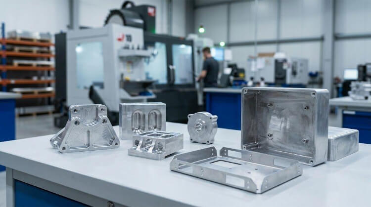
An aluminum prototype is not just a physical representation of a CAD file; it is an engineering testbed. Its primary job is to expose design flaws, validate mechanical behavior, and highlight manufacturing risks before you commit to expensive production tooling or large batch runs.
Getting a prototype right means moving beyond just checking the shape and size. It requires aligning your alloy selection, machining strategy, and finish requirements directly with the final production intent.
Here is a breakdown of what your aluminum prototype actually needs to prove, and how to select the right material to get reliable data.
What an Aluminum Prototype Should Validate?
An effective prototype must generate actionable data. It helps the engineering and procurement teams confirm performance limits, heat response, assembly risks, and the actual boundaries of the machine shop.
Functional performance under active load
A prototype must prove what the part will actually do in the field, not just how it looks on a screen. This stage is about verifying that key features—such as mounting faces, load-bearing paths, and dynamic contact zones—function exactly as intended under working conditions.
If your housing needs to withstand a 2-meter drop test or hold an IP67 waterproof seal, the prototype must be built to validate those exact parameters. It cannot simply sit on a desk for visual approval.
Mechanical and thermal feedback mapping
Aluminum is specified precisely because heat transfer, structural stiffness, or weight reduction matters to the design. In early testing, the prototype must show exactly how the part responds to physical loads, sustained vibration, or thermal cycling (e.g., dissipating heat from a 100W LED module).
This data is only reliable if the prototype’s alloy closely mirrors the intended production route. A 3D-printed plastic stand-in, for example, will give you zero actionable thermal data.
Assembly and tolerance stack-up risks
A part can measure perfectly in isolation but still fail on the assembly line due to tolerance stack-up. Prototypes are essential for checking how the component fits with mating parts, dowel pins, linear rails, or custom brackets.
This is the precise time to identify interference issues. Engineers should use this stage to review critical mating interfaces rather than blindly assigning a ±0.01mm tight tolerance to every single dimension, which unnecessarily skyrockets CNC machining costs.
Machining feasibility and cycle time estimation
Just because a geometry passes a CAD software review does not mean it can be machined stably. Prototyping exposes the reality of the shop floor, revealing how deep pockets (depth-to-width ratio > 4:1), thin walls, and hard-to-reach features drive up cycle times.
These difficult features often introduce chatter during the machining process. If a part vibrates heavily during prototype milling, it will inevitably cause severe tool wear and yield issues during mass production.
Choosing the Right Aluminum Alloy
Machining behavior, forming limits, yield strength, and surface finish requirements change drastically depending on the grade of aluminum. Selecting the right alloy means matching the material to the part’s functional goal, not just pulling whatever stock is cheapest off the shelf.
6061-T6 vs. 7075-T6 machining behavior
For general CNC machining and cosmetic finishing, 6061-T6 is the baseline standard due to its versatility and excellent weldability. However, if your prototype needs to survive extreme stress testing, 7075-T6 offers nearly double the yield strength (up to 500 MPa) and provides superior chip-breaking properties during aggressive milling.
The trade-off? 7075 typically costs 30-40% more, accelerates tool wear, and is notoriously prone to cracking if welded. Don’t over-specify 7075 just for the sake of “better material”—only use it if the functional test strictly demands aerospace-grade structural integrity.
5052-H32 for sheet metal bending limits
When a prototype requires bending, stamping, or flanging, 5052-H32 is the dominant choice. Its elongation properties make it far superior to harder grades like 6061 or 7075, which will almost certainly fracture along a 90-degree bend line.
If your design includes bent covers or server chassis, using 5052 allows you to accurately review critical sheet metal parameters early in the drawing stage. This includes testing the minimum bend radii (typically 1.5x to 2x material thickness), observing material springback, and identifying potential tear risks.
T4 vs. T6 temper conditions and machining distortion
The temper condition of the aluminum directly alters its strength and dimensional stability. A T6 temper (solution heat-treated and artificially aged) maximizes the yield strength, but this hardening process locks intense internal stress into the billet.
When a CNC machine hogs out 80% of the material to create a thin-walled electronic housing, that built-up stress is rapidly released. This reaction often causes the prototype to warp out of tolerance before it even leaves the fixture.
Matching the alloy strictly to the production route
The rule of thumb for material selection must eliminate guesswork:
- For machined structural parts: 6061 is your safest, most cost-effective baseline.
- For formed sheet metal enclosures: 5052 provides the crack-resistance needed for press brake operations.
- For high-load applications: 7075 justifies its cost premium through sheer tensile strength.
Ultimately, if you test a prototype in 7075 machined from a billet, but plan to mass-produce it in die-cast A380 aluminum, your mechanical testing data will be fundamentally flawed. Match the prototype alloy family to the final production intent as closely as possible.
Process Options and Process Limits
The best prototype manufacturing process depends heavily on geometry, validation targets, and positional control needs. A process route that looks highly efficient on a Gantt chart can still destroy your budget if it forces the machinist into awkward setups, introduces thermal distortion, or requires excessive custom tooling.
Multi-axis CNC and setup reduction strategy
A standard 3-axis CNC machine requires the operator to manually flip and re-fixture the part to access different sides. Every single manual flip introduces a stack-up tolerance drift of approximately ±0.02mm to ±0.05mm, ruining tight coaxiality requirements between opposing features.
To eliminate this, highly complex prototypes should utilize 5-axis (or 3+2 positional) machining. By allowing the cutting tool to reach five sides of the part in a single setup, you lock in absolute positional control, ensure seamless surface continuity, and drastically reduce the labor costs associated with custom fixturing.
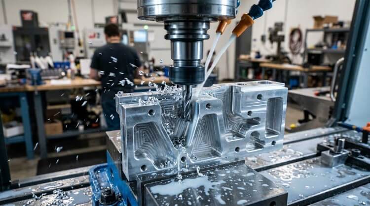
Managing chatter in thin-wall and deep-cavity milling
Thin walls (under 1.5mm) and deep cavities are the most common sources of catastrophic vibration, known as tool chatter, which destroys surface finishes and snaps endmills. When machining aluminum, cutting friction generates intense heat that quickly localizes in thin sections, causing the wall to warp away from the cutter.
To combat this, the shop floor must employ aggressive step-down roughing strategies and leave a uniform layer of material (e.g., 0.2mm) for a final, high-speed, low-pressure finishing pass. However, as an engineer, you must recognize that designing a pocket with a depth-to-width ratio exceeding 4:1 will exponentially increase your prototype risk and cycle time.
Overcoming springback in sheet metal forming
A formed aluminum prototype must be judged by its actual bend behavior on the press brake, not by the flat pattern unfolding perfectly in SolidWorks. When bent, aluminum inherently attempts to return to its original flat state—a phenomenon called springback.
Because different alloys and tempers behave differently (e.g., 5052-H32 springs back less than 6061-T6), the K-factor and bend deductions cannot be treated as fixed, universal numbers. For critical angle tolerances, the shop must often over-bend the prototype by 1 to 3 degrees to compensate, which requires strict material grain direction tracking before the laser cutting even begins.
Wire EDM as a zero-tooling extrusion bridge
If your product relies on a custom aluminum extruded profile (like a finned heat sink or a rail guide), paying $3,000 and waiting 4 weeks for an extrusion die just to test a prototype is a massive risk. If the thermal mass or structural fit is wrong, that die is garbage.
Instead, use Wire EDM (Electrical Discharge Machining) to cut the exact profile out of a solid aluminum block. While slow, Wire EDM easily holds ±0.01mm tolerances and perfectly replicates internal contours without any tooling investment. This allows you to validate the section behavior physically before signing off on the expensive mass-production extrusion die.
Design Details That Affect Prototype Success (DFM)
Many prototype failures are cemented in the drawing long before the raw aluminum reaches the machine. Poor tool access, naive thread designs, conflicting datums, and ignored surface buildup can instantly turn a well-machined part into expensive scrap.
Eliminating sharp internal radii to reduce cycle time
One of the most expensive mistakes a designer can make is drawing a perfectly sharp 90-degree internal corner at the bottom of a deep pocket. Round CNC endmills physically cannot cut square inside corners.
To clear out that corner, the machinist is forced to use a tiny, fragile tool, pushing the length-to-diameter (L:D) ratio past 5:1, which drastically slows feed rates and balloons the cost. By simply adding a realistic internal corner radius—ideally at least 1.2x the radius of the standard tool meant to cut the pocket—you instantly slash machining time and improve the final finish.
Thread forming vs. cutting in soft aluminum
Standard cut taps physically remove aluminum to create threads, which works fine in steel but can leave weak, easily stripped threads in softer aluminum alloys like 6061. If your prototype will undergo repeated assembly and disassembly (e.g., a bolted testing fixture), cut threads will quickly fail.
Instead, specify form taps (roll taps) for your aluminum prototypes. Form tapping displaces and compresses the material rather than cutting it, generating a denser, work-hardened thread profile that is significantly stronger. Always ensure your blind threaded holes are deep enough, providing a minimum of 1.5x to 2x the nominal diameter for proper thread engagement.
Datum structure alignment for reliable inspection
A prototype’s dimensional quality depends entirely on how the part is located, clamped, and measured from stable reference points (Datums). If the CAD model uses the center of a virtual space as Datum A, the machinist has no physical surface to touch off on.
This creates a fatal mismatch: the machinist references a raw stock edge, while the quality inspector’s CMM (Coordinate Measuring Machine) tries to reference a machined hole. To ensure repeatable setups across multiple prototype iterations, your drawing must establish clear, physically accessible datums (like a large, flat machined face or a precision reamed dowel hole).
Pre-machining allowances for hard anodizing
Designers frequently forget that surface finishing is an additive process. If you specify Type III Hard Anodizing for wear resistance, the electrochemical process will add 25 to 50 microns (0.001″ to 0.002″) of aluminum oxide to the surface.
Because anodizing penetrates 50% into the material and builds up 50% outward, a precision H7 sliding fit bore machined perfectly to nominal size will suddenly become too tight after coating, preventing the shaft from inserting. Finish planning and pre-plating dimensional compensation must be locked in before the CNC program is written, not as an afterthought.
Surface Finish and What It Helps You Validate
Surface finish is not a cosmetic afterthought; it is a functional requirement that alters the part’s dimensions, friction coefficient, and thermal emissivity. A prototype that looks perfect in its raw machined state may fail in the field once the final coating is applied.
Bead blasting vs. anodizing: Texture vs. Protection
Bead blasting (e.g., using #120 glass beads) is primarily used to achieve visual uniformity and hide CNC tool marks. It creates a matte, non-reflective texture but provides zero protection against oxidation or wear.
In contrast, Anodizing (Type II) creates a controlled oxide layer that hardens the surface and allows for consistent color dyeing. For B2B industrial products, you must validate both: the tactile feel from blasting and the chemical resistance from anodizing to ensure the part survives its operating environment.
Hard anodizing for wear-related functional testing
If your aluminum prototype is a sliding component or an internal engine part, standard anodizing is insufficient. You must validate with Type III Hard Anodizing, which creates a dense, ceramic-like layer with a thickness of 25 to 50 microns.
This layer significantly increases surface hardness (up to 600-700 HV) but also introduces brittleness. Testing a Type III prototype is the only way to confirm that the part won’t gall or seize under high-friction loads before you commit to the final material spec.
Cosmetic sign-off and color consistency limits
Color matching on aluminum is notoriously difficult because the final hue depends on the alloy chemistry (e.g., 6061 vs. 7075) and the bath temperature. A color that looks correct on a 6061 prototype might appear dull or mismatched on a 7075 production batch.
By finalizing surface finish samples during the prototyping stage, you establish a visual boundary for mass production. This prevents “cosmetic rejection” later in the supply chain and ensures that your procurement team can set realistic color-tolerance expectations with the factory.
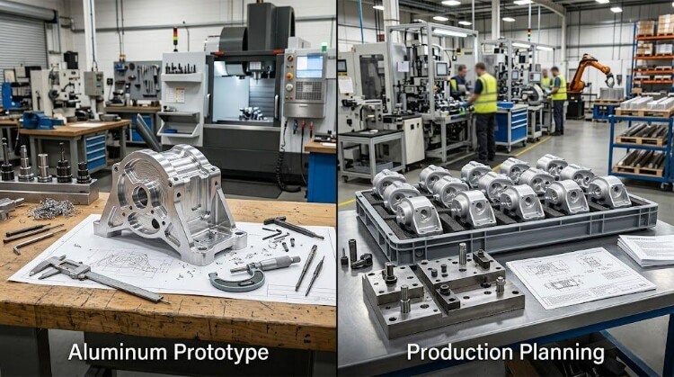
Why Prototype Results Can Differ from Production?
A successful CNC prototype does not guarantee a successful production run. Moving from a single machined block to a high-volume die-cast or stamped part involves a complete shift in manufacturing logic, material flow, and cooling rates.
CNC to die casting: The “Draft Angle” reality
CNC machining allows for perfectly vertical walls and sharp internal corners. However, in die casting, every feature must have a draft angle (typically 1.5° to 3°) to allow the part to eject from the steel mold.
Ignoring draft angles in your prototype stage is a fatal error. Adding them later during tooling design will change the part’s mass, wall thickness, and even its assembly fit. You must review these “production-ready” geometries during the prototype phase to avoid expensive tool rework after the mold is cut.
Geometry adjustments for tooling feasibility
Features that are easy to cut with a CNC tool—like deep, narrow ribs or undercuts—can be impossible or extremely costly to replicate in a mold. For example, a deep rib that causes no issues in a CNC prototype might lead to porosity or cold shuts in a die-casting environment due to poor metal flow.
The transition stage is the time to perform a DFM (Design for Manufacturing) audit. It’s where you trade off prototype “perfection” for production stability, ensuring that wall thicknesses are uniform enough to prevent warping during the rapid cooling cycles of mass production.
Cycle time data as a cost-reduction lever
Every second of machine time removed from a prototype translates into thousands of dollars saved during a 10,000-unit production run. By analyzing the prototype cycle time, you can identify “cost-heavy” features—such as excessive tolerances or non-standard hole sizes—that add no functional value.
Use the data from your prototype builds to perform a value engineering (VE) review. Removing a single complex setup or simplifying a surface finish spec at this stage can reduce your mass-production unit cost by 15% to 30% without sacrificing the part’s core performance.
Conclusion
Aluminum prototyping works best when a team uses it as a decision tool, not just as a sample part. The right alloy, process, and design details help teams check function, reduce machining risk, and find problems early. A good prototype should do more than look right. It should also give clear feedback on fit, heat behavior, surface finish, and the changes that may still be needed before mass production.
An early engineering review can help a project move from prototype to production with fewer problems. If you have a part in development, send us your drawing or 3D file. Our team can review the alloy choice, machining risk, tolerance concerns, surface finish needs, and the best path toward production.