
 English
  Spanish
  German
  Russian
  Italian
  French
Sheet metal notching is a shearing process that removes material from the outer edges of a flat sheet. It prevents flange collisions and material tearing during press brake operations, allowing manufacturers to form clean 3D enclosures and ensure tight corner fit-up.
If you design metal enclosures or brackets, getting the flat pattern wrong means your parts will not bend correctly on the shop floor. Poorly designed notches lead to bulging corners, broken punches, and expensive manual grinding.
This guide breaks down the exact Design for Manufacturability (DFM) rules for sheet metal notching. Below, we cover how to calculate edge clearances, select the right notch shapes to match standard tooling, and optimize your CAD drawings to lower production costs and reduce lead times.
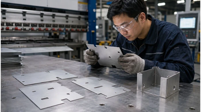
Prevent Interference During Bending
Bending sheet metal changes how the material occupies physical space. Notching removes the material that would otherwise get in the way of this transformation.
Edge Clearance
When folding adjacent flanges to form a box or enclosure, the metal needs space to move. Notching provides this critical edge clearance. If the notch is too small, the metal edges will collide before the press brake reaches the target angle.
This collision causes bulging or flaring at the corner of the bend. Fixing these defects usually requires manual grinding or secondary operations, which adds unnecessary labor costs to the final part.
Bend Relief
Bending puts the material under significant localized stress. If a bend does not extend across the entire length of a part, the material adjacent to the bend can tear or deform along the bend line.
A bend relief notch separates the bent section from the flat section, safely absorbing this stress. As a general rule, the width of a bend relief should be at least equal to the material thickness (or a minimum of 1.5mm), and its depth should clear the bend radius.
Corner Fit-Up
The geometry of the notch determines how the corners align after bending. For parts that require welding, leaving a gap of 0.5mm to 1.0mm (depending on material thickness) works well to allow for proper weld penetration.
For parts that remain unwelded, a tight corner fit-up is usually preferred. This maintains a clean seam and helps prevent dust or moisture ingress into the enclosure.
Flat Pattern
Every 3D sheet metal part starts as a 2D flat pattern. The notching dimensions must account for bend deduction, material thickness, and the K-factor to ensure the final 3D part meets tolerances.
While modern CAD software automatically calculates these flat patterns, verifying the notch geometry on the 2D drawing helps prevent interference issues and costly scrap on the shop floor.
Choose the Notch Shape That Matches the Part
Different assembly requirements dictate different notch shapes. The choice depends on the final function of the part, available tooling, and production volume.
V Notches
A V notch removes a triangular section of material from the edge. It is most commonly used when bending two adjacent flanges to 90 degrees to form a closed corner.
Using standard angle notches (like 90° or 45°) is more cost-effective because the manufacturer can use off-the-shelf tooling. Custom angles may require multiple hits on a CNC turret or specialized punches, which increases setup time and tooling costs.
Corner Notches
Corner notches remove a square or rectangular piece from the edge of the sheet. This shape is frequently used for pan or box forming where adjacent sides need to fold up without intersecting.
This creates a straight, clean edge that makes it easier to align mating components. It is also useful for providing clearance for internal brackets or installing hardware near the corners.
Slit Notches
A slit notch is a narrow, straight cut into the material edge. It serves primarily as a simple bend relief when space on the flat pattern is highly limited. Because slit notches are very narrow, they require careful tooling selection to avoid breaking the punch.
To improve part longevity, it is highly recommended to add a small circular radius at the end of the slit. A sharp termination acts as a stress concentrator, which may cause the material to crack over time under load or vibration.
Tube Notches
Although notching is primarily a sheet metal process, the same geometric principles apply to structural assemblies. Tube notching involves cutting a curved profile into the end of a round or square tube.
This allows the tube to sit flush against another intersecting tube. It is a standard preparation step for creating strong, saddle-style welded joints in structural frames, reducing gaps and improving weld quality.
Design Notches That Bend Cleanly
Proper notch design prevents forming failures on the press brake. Following these specific dimensional rules ensures accurate bends and extends tooling life.
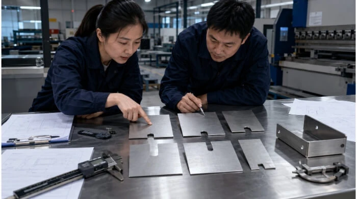
Notch Width
The width of a notch should be at least equal to the material thickness, or a minimum of 1.5mm (0.060 inches). If a notch is narrower than this, the punching tool is highly likely to break due to excessive cutting pressure.
Tool breakage damages the workpiece and causes machine downtime, directly impacting your lead time. For thicker materials, slightly increasing the width provides better die clearance and reduces tooling wear.
Notch Depth
A notch that is cut too deep can weaken the structural integrity of the flange. As a general rule, notch depth should not exceed five times the material thickness.
If a deeper notch is strictly necessary, it usually requires a custom punching sequence or laser cutting. Deep, narrow notches cut by a punch press often cause the material to warp along the edge, compromising final assembly fit.
Bend Line Distance
Placing a notch too close to the bend line leads to unwanted distortion when the press brake applies pressure. The notch edge should stay a distance of at least the material thickness plus the bend radius away from the bend line.
This safe distance ensures the notch remains flat and does not get pulled into the bend zone. Ignoring this rule usually results in warped flanges that fail to align with mating components.
Inside Radius
Designing a notch with a perfectly sharp internal corner creates a stress point where cracks easily initiate. Adding a small inside radius (fillet) distributes the stress more evenly during bending and throughout the part’s lifecycle.
A radius of 0.5mm to 1.0mm is usually sufficient to prevent micro-cracking while maintaining a tight fit-up. This small adjustment significantly improves part durability without adding extra manufacturing costs.
Avoid Cracks, Burrs, and Weak Corners
Poorly planned notches compromise the structural integrity and finish of your final part. Managing stress points and edge conditions prevents costly failures in the field.
Stress Points
Sheet metal inherently tries to spring back to its flat state after bending. This tension concentrates at the corners and the roots of any notches.
Proper bend relief and corner radiusing are essential to manage this tension. Ignoring these stress points often causes premature failure, especially in applications involving heavy loads, vibration, or repeated thermal cycling.
Burr Direction
Mechanical notching operations create a slight burr on the breakout side of the sheet. When planning the flat pattern, it is important to consider the bend direction relative to this burr.
It is generally preferred to keep burrs on the inside of the bend or the interior of the enclosure. This reduces manual deburring, improves handling safety, and prevents interference with mating parts.
Edge Strength
While notching is necessary for clearance, removing too much material weakens the overall edge strength of the flange. This becomes problematic for panels that support internal components or bear structural loads.
If edge strength is a primary concern, designers should minimize notch dimensions to only what is strictly required. Keeping the notch as small as possible ensures the part retains its structural rigidity.
Coating Risk
Notches with sharp edges or heavy burrs interfere with surface finishes like powder coating or painting. During curing, paint naturally pulls away from sharp corners—a phenomenon known as edge pull.
This leaves the metal exposed and prone to rust. Ensuring smooth, radiused notches helps the coating adhere evenly, which is critical for outdoor enclosures requiring strict corrosion resistance.
Select the Right Process for Volume and Shape
The best notching method depends entirely on your design complexity and production scale. Balancing speed, precision, and tooling costs dictates which machine fits the job.
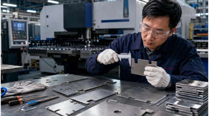
Manual Notching
Manual or hydraulic notching machines are often used for prototypes or very small production runs. They work well for standard 90-degree corner notches and require minimal setup time.
However, because the process relies heavily on the operator for alignment, it is less consistent. It is not suitable for complex geometries or high-volume orders where strict repeatability is required.
CNC Turret Punching
For medium to large production volumes, CNC turret punching is highly efficient. A turret press can perform multiple notching operations in seconds using standard tooling, making it cost-effective per part.
The limitation is that non-standard notch shapes require custom punches or multiple overlapping hits (nibbling). Nibbling slows down the machine cycle time and leaves small scallop marks along the edge.
Laser Cutting
Laser cutting offers complete flexibility for notch design, as it does not rely on physical tooling. It is the best choice for intricate notch profiles, custom angles, or extremely thick materials.
However, laser cutting creates a Heat-Affected Zone (HAZ) along the edge, potentially causing micro-cracking during tight bends. Additionally, the slower cycle time makes it less cost-effective for high volumes of standard parts.
Stamping Tooling
Progressive stamping dies are used for mass production, typically for orders in the tens or hundreds of thousands. The notching operation is built directly into the custom die set, allowing for extremely fast cycle times.
While the individual piece price drops significantly, the NRE (Non-Recurring Engineering) costs for custom dies are high. This process only becomes cost-effective when the tooling investment is amortized over a massive production run.
Control Tooling and Production Cost
Manufacturing costs scale quickly when standard practices are ignored. Optimizing your notch design for existing equipment keeps tooling budgets and cycle times manageable.
Standard Tools
Using standard notch shapes, such as 90-degree corners or simple rectangles, keeps your production costs low. Manufacturers already stock standard punches and dies for these common geometries.
Relying on off-the-shelf tooling eliminates the need to purchase new equipment. It also allows the factory to set up the punch press faster, which directly reduces your overall part price.
Custom Tools
Designing non-standard angles or highly complex edge profiles requires bespoke tooling. Purchasing custom punches and dies incurs NRE (Non-Recurring Engineering) costs and can add weeks to your initial lead time.
Custom tooling only becomes cost-effective at high volumes where the expense is absorbed across tens of thousands of parts. A reliable manufacturing partner will flag non-standard notches during the initial DFM review and suggest minor design tweaks to fit standard tooling, saving you both time and NRE costs.
Setup Time
Every time an operator changes a tool on a punch press, the machine stops running. Designing parts that require multiple different notch sizes increases this setup time and lowers manufacturing efficiency.
Standardizing notch dimensions across a single part—or an entire product family—minimizes tool swapping. Keeping the turret loaded with the same standard tools speeds up production and lowers your machining costs.
Deburring
Edge quality directly impacts the amount of manual labor required after the parts leave the press. Improper die clearances or overlapping punch hits (nibbling) leave heavy burrs along the notch.
Manual deburring is a slow and expensive secondary operation. Designing notches that can be cut cleanly in a single hit reduces this labor requirement and keeps your unit price down.
Send Clear Drawings Before Quoting
Ambiguous drawings lead to inaccurate quotes and manufacturing delays. Providing explicit instructions ensures the factory cuts exactly what you need. Always provide a 3D CAD model (such as a STEP file) alongside a 2D PDF drawing. The 3D model clarifies the final intent, while the 2D drawing dictates tolerances and finishes.
Material Grade
Different metals behave differently under cutting pressure. A notch clearance that works perfectly for soft aluminum might cause high-carbon steel to crack or wear out the tooling.
Always specify the exact alloy and temper on your drawing. This allows the manufacturing engineers to calculate the correct die clearances and tonnage before production begins.
Bend Direction
Clearly indicate which way the flanges fold on your 2D flat pattern, typically marked as “BEND UP” or “BEND DOWN.” This tells the press brake operator how to orient the part.
Knowing the bend direction ensures the burr is placed on the inside of the enclosure. It also guarantees that bend reliefs are positioned correctly relative to the mating components.
Critical Dimensions
Not all dimensions carry the same functional weight. Highlight which notch dimensions are critical for corner fit-up, hardware installation, or welding gaps.
Applying specific tolerances to these critical areas tells the QA team exactly where to focus their inspections. Loosening tolerances on non-critical edges helps the factory run the part faster without unnecessary rejections.
Edge Finish
State clearly if the part will be powder coated, painted, or handled frequently by end-users. Calling out edge break or deburring requirements upfront prevents miscommunication.
If edge quality is not specified, the factory may assume a standard machined finish, which could leave sharp corners. Defining these requirements early prevents unexpected charges for manual finishing later.
Conclusion
Sheet metal notching is a foundational step that dictates the success of your forming and assembly processes. By following basic DFM rules for width, depth, and corner radii, you prevent material tearing, reduce scrap, and avoid costly manual rework.
The best designs balance functional fit-up with the realities of machine tooling. Keeping notches standardized and properly distanced from the bend line ensures a clean transition from 2D flat patterns to reliable 3D parts.
Need help optimizing your sheet metal flat patterns for production? Our engineering team can review your CAD files to ensure a clean, cost-effective build. Upload your CAD files today for a free DFM review and a fast, accurate manufacturing quote.
FAQs
What is the difference between notching and punching?
Notching removes material from the outer edges of a sheet metal part to shape the perimeter or prepare for bending. Punching creates enclosed shapes, such as holes or slots, completely within the interior of the material.
Can I laser cut notches instead of punching them?
Yes. Laser cutting works well for prototypes, complex shapes, or thick materials. However, it creates a Heat-Affected Zone (HAZ) that can slightly harden the material edge, and it is usually slower and more expensive than CNC punching for large-volume standard parts.
How wide should a bend relief notch be?
The width of a bend relief should be at least equal to the material thickness, with a minimum width of 1.5mm (0.060 inches). If the notch is too narrow, the material is likely to tear during the bending process, and the cutting tool is at a higher risk of breaking.
What is the maximum material thickness suitable for punch press notching?
While it depends on the specific alloy and machine tonnage, punch notching is generally highly effective for sheet metal up to 3mm (0.118 inches) thick. For materials thicker than 3mm, laser cutting often becomes the more practical and cost-effective method to avoid excessive tool wear and edge deformation.