
 English
  Spanish
  German
  Russian
  Italian
  French
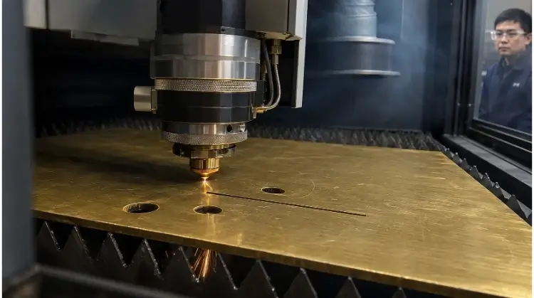
Brass laser cutting is a thermal manufacturing process using high-power fiber lasers to cut complex profiles from brass sheets. Because brass is highly reflective and thermally conductive, successful processing requires specialized back-reflection protection, high-pressure nitrogen, and strict parameter controls to prevent optical damage and bottom dross.
Unlike carbon steel or stainless steel, brass cannot be processed using standard laser parameters. Variables such as rapid heat dissipation, piercing spatter, and surface scratching frequently disrupt production stability. Because raw brass is a high-cost material, optimizing this process is not just about achieving a clean edge—it is about minimizing scrap, preventing machine downtime, and maximizing material yield.
Reliable processing results depend on the specific brass grade, sheet thickness, part geometry, laser system capabilities, assist gas, and cosmetic requirements. This guide directly breaks down the validated shop-floor parameters, Design for Manufacturability (DFM) rules, and hidden cost drivers you need to know before issuing an RFQ.
Quick Reference for Brass Laser Cutting
| Item | Practical Application |
| Common Equipment | Fiber laser systems explicitly designed for highly reflective (high-rel) materials. |
| Assist Gas | High-pressure nitrogen. Specific pressure depends on the machine and sheet thickness. |
| Suitable Parts | Complex flat profiles, prototypes, custom components, and low-to-medium volume runs. |
| Primary Risks | Back reflection, cut loss, bottom dross, edge taper, discoloration, and surface scratching. |
| RFQ Requirements | Grade, temper, thickness, drawing (DXF/STEP), quantity, critical tolerances, and cosmetic needs. |
Brass Sheet Selection Before Cutting
Material specifications must be confirmed before programming the laser. Treating all brass sheets as identical materials often leads to inconsistent edge quality and part rejection.
Grade, Temper, and Lead Content
The ratio of copper to zinc, material temper, and lead content directly influence cutting stability, bending performance, subsequent machining, and fume generation. C26000 (Cartridge Brass) is a common sheet material that laser cuts consistently due to its high zinc content and predictable thermal properties.
💡 Material Note: C36000 (Free-Machining Brass)
C36000 contains lead to improve chip breakage and is typically supplied as bar stock for CNC turning and milling. It should never be specified as a direct substitute for standard brass sheet in laser cutting. Thermal processing of leaded brass vaporizes the lead, posing severe environmental and health risks to the shop floor.
Thickness and Flatness
Sheet thickness and overall flatness determine the focus position, piercing time, penetration capability, and the likelihood of bottom dross. A sheet with poor flatness forces the capacitive height sensor in the cutting head to constantly adjust. In highly reflective materials, this can easily destabilize the cut, leading to mid-sheet cutting failures and high scrap rates.
The maximum achievable cutting thickness is not a fixed metric. It must be evaluated alongside the available laser power, cutting head design, gas delivery system, and the acceptable level of edge taper.
Cosmetic Face and Protective Film
For parts requiring a specific finish, the drawing must clearly indicate the cosmetic face, brushing direction, cosmetic zones, and whether a protective film is required during processing.
The manufacturing facility must confirm if the specified protective film is suitable for laser processing through trial cuts, checking for excessive melting, edge bubbling, or nozzle contamination. If standard PVC film is supplied instead of a laser-rated film, the manufacturer must manually remove it before cutting, which adds labor costs and increases the risk of surface scratches during handling.
Back Reflection and Cut Stability
Brass is inherently difficult to cut due to its high reflectivity in a solid state and its rapid thermal conductivity. Managing these variables on the production floor is critical to maintaining yield.
Laser System and Optical Protection
The laser system used must explicitly support the processing of copper and brass. Key hardware checks include:
- Laser Source: Must feature built-in back-reflection isolation and automatic beam shut-off alarms.
- Cover Glass: Requires strict inspection routines for contamination.
- Nozzle Concentricity: The beam must be perfectly centered to prevent heating the copper nozzle.
- Cutting Head: Routine calibration to ensure focus accuracy.
It is important to distinguish between the risks: back reflection risks catastrophic damage to the laser source and collimator, whereas piercing spatter and fumes primarily contaminate the lower protective cover glass, degrading cut quality over time.
Piercing, Focus, and Cutting Speed
The piercing stage is the most unstable phase of brass cutting. Before the beam penetrates the sheet, the solid brass reflects a high percentage of the laser energy back through the optics while generating upward molten spatter.
Stable cutting requires a strict balance between power, focus, and travel speed. Moving the cutting head too slowly allows heat to dissipate into the surrounding material, causing the brass to boil and form heavy bottom dross. Conversely, moving too quickly may cause the beam to lose the cut entirely (blowout).
💡 Shop Note: Piercing Film-Covered Brass
For brass supplied with laser-rated film, some advanced control systems allow a two-stage pierce: a low-power pass to vaporize the plastic film, followed by a full-power pierce through the metal. However, this is not a universal solution for all films and requires prior validation on scrap material to prevent plasma instability.
Assist Gas, Nozzle, and Fume Control
High-pressure nitrogen is used to mechanically flush the molten brass out of the kerf and prevent oxidation, resulting in a bright, gold-colored edge. While high-pressure nitrogen guarantees a clean edge, it is also the highest consumable cost in brass cutting. Balancing pressure with edge requirements is key to cost control.
The effectiveness of the gas depends on the nozzle diameter, beam centering, and gas purity. Using chrome-plated nozzles is a verified shop practice for yellow metals; the plating prevents sticky brass spatter from adhering to the nozzle tip, which would otherwise confuse the height sensor and cause head crashes.
Safety is also a primary concern. Vaporized zinc generates toxic white fumes (zinc oxide). Laser cutting brass requires a fully enclosed machine cabin connected to an industrial dust collection and extraction system.
Validated Starting Parameters for Brass Sheet
Fixed Test Conditions:
- Material: C26000 Brass Sheet, Half-Hard
- Laser System: 6kW Fiber Laser
- Cutting Head: Standard Autofocus Head
- Assist Gas: Nitrogen (99.99% Purity)
- Surface: Bare (No Protective Film)
| Thickness (mm) | Power (W) | Speed (m/min) | Focus Position (mm) | Nozzle Type | Nitrogen Pressure (Bar) | Expected Edge Result |
| 1.0 | 6000 | 25.0 | -0.5 | Single, Chrome | 14 | Clean, minimal striations |
| 3.0 | 6000 | 8.0 | -1.5 | Single, Chrome | 16 | Clean, slight visible dross |
| 6.0 | 6000 | 2.5 | -3.0 | Single, Chrome | 18 | Visible striations, dross requires deburring |
Note: These values are validated starting points for the stated machine and material setup. Production parameters always require a trial cut to account for machine-specific variances and material batch differences.
DFM Rules for Brass Laser-Cut Parts
Optimizing a design for laser cutting requires an understanding of how the laser beam interacts with the specific alloy. Design for Manufacturability (DFM) rules must be applied before the drawing reaches the quoting stage to prevent production delays, high scrap rates, and inflated costs.
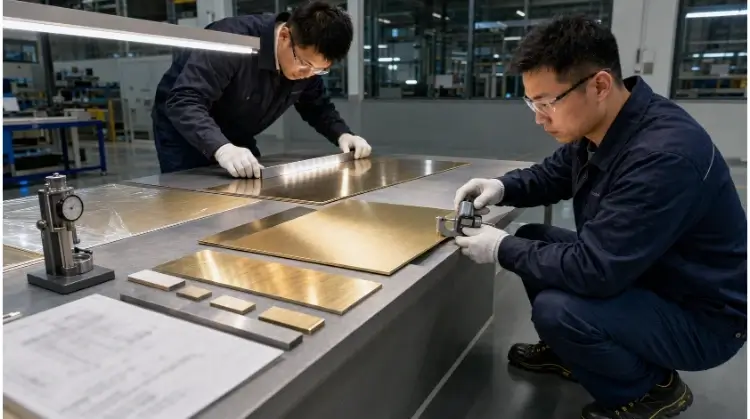
Holes, Slots, and Narrow Features
The rapid heat transfer in brass means that narrow web areas (the material between two cuts) can quickly melt or distort during processing. Hole diameters and slot widths must always be scaled relative to the sheet thickness (t).
For C26000 brass processed on a fiber laser (thickness < 6mm):
- Minimum Hole Diameter: While mild steel can accommodate 1t, brass typically requires a minimum hole diameter of 1.2t to 1.5t to prevent the piercing heat from destroying the hole’s geometry.
- Minimum Slot Width: Slots should be no narrower than 1.2t.
- Minimum Web Thickness: The distance between two holes or a hole and the outer edge must be at least 1.5t. Narrower webs risk catastrophic melting or severe thermal distortion.
💡 Cost Impact: Designing holes smaller than 1.2t forces the manufacturer to use secondary CNC drilling operations. This significantly increases machine setup time, tooling wear, and per-part cost.
Kerf, Lead-Ins, and Critical Features
The laser beam has a physical width, creating a cut gap known as the kerf (typically 0.15mm to 0.25mm, depending on focus and sheet thickness). While CAM software automatically compensates for kerf on the toolpath, the piercing process requires a “lead-in” line to start the cut outside the final part geometry.
Lead-ins leave a microscopic witness mark (a small bump or dimple) where the cut starts and finishes. If a part has a strict functional edge that must remain perfectly flush, the engineering drawing must explicitly specify where lead-ins are prohibited.
When Laser Cutting is Not Enough:
A laser-cut hole is inherently unsuitable for precision press-fits or locating pins. The natural slight taper of the laser cut and the lead-in mark will interfere with assembly. For critical mating features (e.g., H7 bearing tolerances), the standard DFM strategy is to laser-cut the hole undersized by 0.5mm, followed by a secondary CNC boring or reaming operation.
Small Parts, Micro-Joints, and Heat Distribution
Small parts (under 50mm) risk tipping and falling through the machine’s support slats during cutting, which can cause fatal collisions with the cutting head. To prevent this, programmers use micro-joints (small un-cut tabs) to keep the part attached to the sheet skeleton.
Breaking these joints leaves a small burr. For cosmetic parts, local hand-grinding to remove this burr destroys the surrounding surface finish. A proper DFM review will strategically place micro-joints on non-visible edges or inside internal scrap cutouts to avoid cosmetic rework entirely.
The Danger of Dense Nesting:
Buyers often request “common line cutting” (where two parts share a single cut path) or extremely tight nesting to save expensive brass material. However, tightly nesting brass parts concentrates the heat. This rapid heat buildup can cause the entire sheet to warp, leading to sensor errors and out-of-tolerance parts. Spacing parts further apart slightly increases material consumption but is often necessary to stabilize the cutting process and guarantee yield.
Tolerances and Finish Requirements
“High precision” and “clean edges” are subjective terms that cause disputes between buyers and manufacturers. To ensure quality and control costs, these expectations must be translated into measurable specifications on the RFQ and inspection documents.
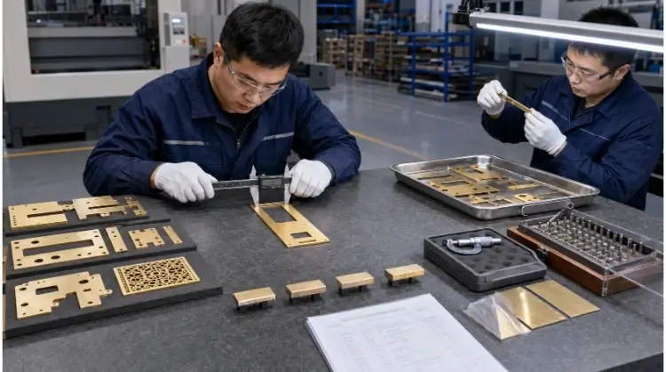
Dimensional Tolerances and Inspection
Standard linear tolerances for laser cutting are frequently cited as ±0.1 mm, but this is not a blanket guarantee. Over-specifying tolerances (e.g., a blanket ±0.05 mm across the entire drawing) will often result in a “no-quote” or force the supplier into expensive CNC routing. Only apply tight tolerances to critical mating features.
An accuracy of ±0.1 mm is practically achievable under these specific conditions:
- Material: C26000 Brass, 1.0mm to 3.0mm thickness.
- Size Range: Part dimensions under 100mm.
- Inspection Method: Calipers or CMM.
- State: Measured after standard deburring, but without secondary CNC edge milling.
As the sheet thickness or overall part dimension increases, the tolerance band must widen naturally (e.g., ±0.2 mm is standard for 6mm thick brass).
Edge Defects and Acceptance Limits
Due to its fluidity when molten, laser-cut brass is highly prone to bottom dross (slag), edge taper, and striations. Clearly stating your acceptable edge level in the RFQ prevents overpaying. Specifying Level 1 for a hidden structural bracket wastes money; under-specifying for a decorative lighting panel ruins the final product.
Production edges are generally categorized into four QC acceptance levels:
- Acceptable As-Cut: Clean edge, clear vertical striation lines, zero sharp dross on the bottom edge. Acceptable for internal structural components.
- Acceptable After Deburring: Noticeable bottom dross present after cutting, but completely removed via mechanical brushing or vibratory tumbling. The edge is smooth to the touch.
- Rework Required: Severe edge taper, heavy discoloration, or thick dross that cannot be removed by standard tumbling. Requires secondary edge machining or manual grinding to meet specification.
- Reject: Blowout (loss of cut), melted corners, or severe thermal warpage. The part fails dimensional inspection.
Deburring, Cosmetic Finishing, and Protection
It is crucial to differentiate between the edge quality generated by the laser and the surface cosmetics of the sheet. Standard deburring operations (such as tumbling or wide-belt sanding) effectively remove edge dross but will completely alter or ruin the raw surface finish of the brass sheet.
If the brass part is an external cosmetic component (e.g., architectural panels, luxury hardware), it requires specialized processing:
- Surface Finishes: The drawing must specify if the part requires post-cut directional brushing (e.g., #4 finish), mirror polishing, or protective clear coating/electroplating to prevent natural tarnishing.
- Handling & Packaging: Brass scratches exceptionally easily, and the zinc/copper alloy reacts quickly to the oils in human hands, causing dark oxidation spots. Production notes must explicitly specify glove-only handling. To prevent transit damage—a massive driver of rejected parts—components must be packaged with interleaving paper or foam separators to prevent surface-to-surface scratching.
Cost and Supplier Decisions
Procurement managers often see wild variations in quotes for brass components. Understanding the underlying cost drivers and knowing when to switch manufacturing processes are essential for controlling budgets and avoiding supplier-side failures.
Material Yield and Cutting Time
Unlike carbon steel, the raw material cost of brass dominates the final piece price. However, the machine hour rate for cutting yellow metals is also inherently higher due to the massive consumption of assist gas and optical consumables.
The primary cost drivers in brass laser cutting include:
- Material Price and Yield: The sheer cost of the alloy means that nesting efficiency dictates the baseline price.
- Piercing Count vs. Cut Length: Piercing takes more time and burns more energy than linear cutting. A part with 50 internal cutouts costs significantly more than a solid profile of the same size.
- Nitrogen Consumption: High-pressure nitrogen (up to 22 Bar) is expensive. Thick brass parts require massive gas flow, quickly escalating the hourly running cost.
- Consumable Wear: High-rel materials degrade protective cover glasses and nozzles faster than mild steel.
- Cosmetic Protection: Manual film removal, deburring, and specialized anti-scratch packaging add heavy labor costs.
- Scrap Recovery Value: Brass scrap retains high market value. A highly capable supplier will deduct the recycling value of the brass skeleton from your final quote—sometimes offsetting raw material costs by up to 15-20% on heavily nested sheets.
💡 Cost Impact: DFM Optimization Case Study
A buyer submitted a 3mm brass panel with hundreds of 2mm ventilation holes.
- Original Design (As Quoted): 150 individual pierces. Heavy heat buildup caused warping. Cutting Time: 45 minutes. Yield: 60%.
- Optimized Design (After DFM): Replaced small circular holes with longer routed slots, and adjusted part spacing. Pierces reduced to 40. Cutting Time: 18 minutes. Yield: 75%.
- Result: Unit cost dropped by 42% while entirely eliminating the thermal warpage defect.
Laser, Waterjet, Stamping, and CNC
Laser cutting is not always the most economical choice. Procurement must match the process to the part’s volume, thickness, and functional requirements.
- Fiber Laser: The optimal choice for complex flat profiles, rapid prototyping, and low-to-medium volume production. It offers zero tooling costs and fast turnaround but introduces a Heat-Affected Zone (HAZ).
- Waterjet Cutting: A cold-cutting process. Best for brass parts where thermal distortion or HAZ is strictly prohibited (e.g., aerospace components) or for plates thicker than 12mm. It is slower and generally more expensive per part than laser cutting.
- Metal Stamping: The undisputed choice for high-volume production (e.g., >10,000 units) of thin brass parts. The high initial tooling (die) cost is rapidly amortized, resulting in the lowest possible unit price.
- CNC Machining: Required for extremely thick brass blocks, parts with 3D features (pockets, threads), or components requiring tight mechanical tolerances (like bearing press-fits) that a laser kerf cannot hold.
Conclusion
Successful brass laser cutting relies on an uncompromising balance of physics and equipment. The specific brass grade, the laser’s optical protection systems, the piercing strategy, focal depth, cutting speed, and nitrogen pressure must all work together to stabilize the melt pool and prevent catastrophic damage to the machine.
For buyers and engineers, the work happens before the laser fires. DFM rules, strict tolerance definitions, cosmetic finish requirements, order volumes, and secondary machining needs must be locked down during the RFQ stage. Treating brass like standard steel is a guaranteed path to rejected parts and blown budgets.
Request a DFM Review for Your Brass Parts
Upload your DXF or STEP files with the brass grade, thickness, and finish requirements. Instead of just a price tag, our engineers will provide a Free DFM & Cost-Reduction Report along with your quote within 24 hours. Need it fast? We also support rapid prototyping runs before you commit to full production.