
 English
  Spanish
  German
  Russian
  Italian
  French
Deburring is a secondary manufacturing process used to remove burrs, sharp edges, and loose material fragments left on a workpiece after machining or cutting operations. It ensures part safety, tight tolerances, and proper assembly fit.
While the definition is straightforward, selecting the right deburring method is a complex engineering decision. The optimal process depends entirely on the burr type, part geometry, material properties, and production volume. Treated merely as an afterthought, manual deburring can easily become a hidden bottleneck that increases scrap rates and destroys profit margins.
This guide explains how to identify edge defects, match the deburring process to the material behavior, reduce burr formation at the CNC machine, and objectively inspect the finished edge.
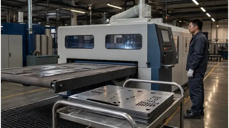
What Deburring Removes From a Manufactured Part
Before selecting a tool, engineers must identify the specific edge defect and determine the required final state of the part.
Burrs, Dross, and Sharp Edges
- Burrs: Raised ridges, thin fins, or loose fragments of material left on an edge after machining.
- Sharp edges: A machined 90-degree corner may have no visible burr, but it remains a sharp edge that can injure personnel or damage mating assemblies.
- Thermal dross: Melted material that resolidifies on the bottom of a cut. It is often much harder than the base material.
- Plastic flash: Excess material extruded between mold halves. It behaves differently under abrasive tools than metal cutting burrs.
- Weld spatter: Fused metal droplets on the surface, which usually require heavy grinding rather than standard edge deburring.
Common Burr Forms
| Burr form | How it forms | Typical location |
| Rollover burr | Material bends before separation | Milling exits and cut edges |
| Poisson burr | Material deforms under cutting pressure | Machined edges |
| Tear burr | Material tears during separation | Punching and shearing |
| Cut-off burr | Material remains at the final connection | Sawing and parting |
| Thermal dross | Melted material solidifies on the edge | Laser and plasma cutting |
These classifications help machinists troubleshoot the cutting process at the source. However, the actual deburring method selection relies more on the burr’s size, its location, and the final edge requirement.
Why Edge Condition Matters
The requirement to deburr a part is usually driven by functional and safety requirements:
- Burrs routinely cut operators and end-users during handling.
- Raised material prevents flat mating surfaces from seating and shifts hole centerlines, causing alignment issues.
- Sharp edges easily slice O-rings, wire insulation, and pneumatic hoses.
- Loose metallic fragments can detach and destroy hydraulic valves or motion systems.
- Sharp corners cause paint or powder coat to thin out, leaving the edge vulnerable to rust.
- Irregular edges cause unpredictable gap variations during assembly.
- Localized edge defects act as stress concentration points, increasing fatigue failure risks.
Whether an edge defect actually causes a failure depends entirely on the part’s function and allowable clearances. A 0.1 mm burr may cause a critical leak in a high-pressure manifold, but the same defect might be acceptable on an internal structural bracket. However, for OEMs, a burr discovered during final assembly is exponentially more expensive to fix than one controlled at the machining center.
Choose the Deburring Method by Geometry and Volume
Selecting a deburring process requires balancing edge specifications against production volume. A method that works well for a 10-piece prototype run usually becomes inefficient and costly for a 10,000-piece order.
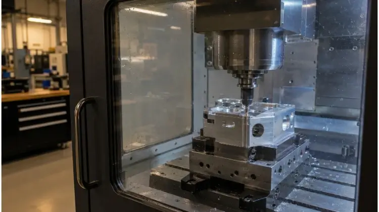
Manual and In-Machine Tools
Manual deburring utilizes hand scrapers, files, countersinks, rotary burrs, abrasive pads, and flap wheels. It works well for prototypes, low-volume batches, localized rework, and highly accessible edges where the operator needs to avoid critical threads or cosmetic surfaces.
However, manual deburring introduces human inconsistency into an otherwise precise CNC process. It increases dimensional variation, extends per-part cycle times, and often forces QA teams to inspect 100% of the edges instead of relying on statistical process control (SPC). Rotary tools can also introduce localized heat, vibration marks, and unintended scratches.
In-machine CNC deburring uses chamfer mills, back-burr cutters, spring-loaded tools, and floating holders directly inside the milling or turning center. By keeping the part in the machine, this method eliminates secondary handling, flipping, and refixturing. It is highly suited for repeated production runs. Rather than relying on hand pressure, in-machine deburring improves edge dimension consistency and ensures every part matches the programmed toolpath.
Belt, Brush, and Batch Finishing
When production volume increases, individual edge processing is often replaced by continuous or batch equipment.
| Method | Suitable parts | Main advantage | Main limitation |
| Belt deburring | Flat sheet metal | Fast processing | May round corners |
| Rotary brush | Light, uniform burrs | Treats several edge directions | May miss thick burr roots |
| Vibratory finishing | Small durable parts | Processes batches together | May damage cosmetic surfaces |
| Barrel finishing | Small simple parts | Low handling per part | Limited edge control |
| Robotic deburring | Repeated complex parts | Stable automated path | Fixture and programming cost |
These high-volume methods carry specific risks. High-pressure belt sanders can easily warp thin sheet metal. Brushes and belts may over-sand small holes or protruding bosses, washing out their dimensions. On cosmetic parts, rotary brushes can create cross-grain scratches if the part has an existing directional brushed finish. Batch processing (vibratory or barrel) carries the risk of part-on-part impingement, and abrasive media frequently becomes lodged in blind holes, threaded bores, or tight internal cavities.
Internal and Hard-to-Reach Burrs
Complex manifolds, intersecting cross-holes, and internal cavities require specialized processes where standard mechanical tools cannot reach. Common methods include:
- Back-burr tooling
- Thermal energy deburring (TEM)
- Electrochemical deburring (ECD)
- Abrasive flow machining (AFM)
- High-pressure water deburring
- Cryogenic deburring
When evaluating these processes, engineers must ask specific questions: Can the tool or media reach the root of the burr? Can the process handle intersecting holes without damaging the main bore? Will it form the required edge radius, or just remove loose material? Will it thin out sensitive walls? Importantly, processes like TEM, ECD, and AFM leave residues, meaning the parts must go through a dedicated cleaning cycle afterward.
Total Cost and Sourcing Considerations
Total deburring cost = labor + machine time + consumables + handling + cleaning + inspection + rework + scrap.
When evaluating whether to bring deburring in-house or outsource it, procurement managers should compare:
- Monthly volume and product lifecycle
- Per-part processing time and changeover frequency
- Upfront fixture and CNC programming costs
- Ongoing consumable wear and machine maintenance
- Scrap rates and rework labor
- Outsourcing logistics (transportation and lead time delays)
There is no universal break-even point for capital equipment. The stability of the production volume and the utilization rate of the machine are usually more important than the initial purchase price. For many OEMs, investing in specialized deburring equipment yields a poor ROI compared to partnering with a CNC supplier capable of delivering ready-to-assemble, completely burr-free components directly from the machine.
Workshop Safety and Compliance
Deburring generates physical hazards that require baseline workshop controls:
- Proper eye protection and machine guarding for flying debris.
- Monitoring for hand-arm vibration and noise exposure from rotary tools.
- Dust extraction for metal and composite particulates.
Certain materials, particularly aluminum, magnesium, and titanium, generate highly combustible dust during deburring. Facilities must follow specific material risk assessments, utilize wet-dust collectors where required, and adhere strictly to local fire and safety regulations to prevent deflagration risks.
Match the Process to Material Behavior
Selecting a deburring tool based solely on part geometry is insufficient. The physical properties of the material—specifically its ductility, hardness, and thermal sensitivity—dictate how the burr behaves under mechanical action.
Soft and Ductile Metals
When machining aluminum, copper, and certain brass alloys, the primary challenge is the material’s tendency to smear and adhere to the cutting tool. Because these metals are highly ductile, a dull deburring tool will simply push the material around the edge rather than cleanly shearing it off.
Many shops make the mistake of applying excessive abrasive pressure to aluminum parts. This often flattens the burr into the parent material without removing the root. This creates a hidden defect (a “flake”) that can detach later during vibration, potentially seizing a hydraulic valve or shorting an electrical assembly.
Additionally, high-pressure deburring easily warps thin sheet metal and scratches cosmetic surfaces during clamping or batch processing. For soft metals, utilizing sharp tools and stable cutting action is usually far more effective than abrasive rubbing. Process parameters must be adjusted based on the specific alloy grade, tool diameter, and burr size rather than relying on a universal spindle RPM.
Stainless Steel and High-Performance Alloys
Materials like stainless steel, titanium, and nickel-based alloys present the opposite challenge: they are highly prone to work-hardening. If a deburring tool rubs against a 304 stainless steel edge without aggressively cutting into it, the localized friction generates heat and hardens the burr.
Once the edge work-hardens, the deburring tool wears out rapidly, often creating new secondary burrs. On critical aerospace or medical components, the hardness of a smeared edge may even differ from the bulk material, causing compliance issues. Stable, aggressive cutting feeds are generally more important than simply increasing spindle speed.
Deburring is often the final mechanical step in production. Ruining a complex titanium manifold through improper deburring does not just waste raw material—it destroys hours of expensive CNC machining time. While ceramic fiber brushes, specialized carbide tools, and aggressive abrasives work well for these alloys, facilities must strictly validate tool life limits to prevent catastrophic late-stage scrap.
Plastics and Composites
Engineers cannot directly apply metal deburring parameters to plastics and composites. Thermoplastics are highly sensitive to friction; excessive RPMs will soften the plastic, causing it to re-fuse along the edge rather than breaking away. Flexible polymers often form stringy, resilient flash that resists standard abrasive media, while excessive mechanical pressure easily deforms thin plastic walls.
For carbon fiber reinforced polymers (CFRP) and fiberglass, the risk shifts to structural damage. Improper deburring tools will cause delamination or pull structural fibers out of the resin matrix, ruining the part’s integrity. Furthermore, worn cutting tools exacerbate hole-exit damage in composites. Finally, deburring these materials generates hazardous fine dust, requiring facilities to implement source-capture extraction systems specifically rated for combustible or respiratory hazards.
Reduce Burrs Before Secondary Finishing
The most cost-effective way to manage deburring is to prevent severe burrs at the primary machining or cutting stage.
Tool Condition and Cutting Direction
Machinists should replace cutting tools before they reach catastrophic failure. A worn end mill dragging across an exit edge will roll a massive, hardened burr that secondary tools cannot efficiently remove.
To minimize burr formation, programmers should check tool entry and exit points. When suitable for the setup, climb milling helps push the burr in a preferred direction, though it is not a universal cure—burr formation is still heavily influenced by the material, fixture rigidity, and tool exit angle. Supporting the material at drill breakout points, reducing chatter on thin walls and overhangs, and ensuring stable shearing action all contribute to keeping the incoming burr size consistent.
Laser, Punch, and Shear Settings
For sheet metal fabrication, heavy edge defects usually point to incorrect machine parameters.
When evaluating laser cut edges, engineers should verify focal position, assist gas pressure, nozzle condition, and cutting speed. Poor material support or a contaminated sheet surface can also worsen thermal dross. For punching and shearing operations, heavy tear burrs are directly tied to improper die clearances for the material thickness, worn punch blades, or excessive sheet distortion during the stroke.
Process Control Priority
Automated deburring machines expect a uniform incoming edge. If the burr size fluctuates wildly due to dull punch dies or worn end mills, the deburring machine will either under-process the heavy burrs or over-process and ruin the clean edges. When a burr suddenly thickens or changes location, facilities must first inspect and correct the primary cutting process rather than simply adding more time and pressure to the secondary deburring cycle.
CAD Edges and Tool Access
Design for Manufacturing (DFM) is the strongest defense against excessive deburring costs. Engineers should address edge conditions directly in the CAD model and 2D drawings.
Specify chamfers or radii only when functionally required—such as for assembly lead-ins or stress relief. For critical sealing faces or locating datum edges, specify the exact edge condition required. Conversely, explicitly mark functional edges that must remain sharp.
When designing internal features, avoid creating closed cavities or intersecting blind holes where deburring tools cannot reach and abrasive media cannot be washed out. Ensure that adding a designed chamfer does not inadvertently thin out a critical wall or interfere with a mating component.
The Cost of Ambiguity
Ambiguous drawing notes force manufacturers to price in the worst-case scenario. A blanket “break all edges” note forces CNC shops to quote expensive manual labor on non-critical geometry just to ensure compliance. Explicitly defining edge conditions lowers your quoted price, eliminates guesswork, and ensures consistent quality. Use notes like “Chamfer 0.5 mm × 45°” only for specific, required edges rather than a default for the entire part.
Control the Finished Edge in Production
Deburring is not just about removing material; it is about protecting the part, clearly communicating requirements on drawings, and verifying the final result objectively.
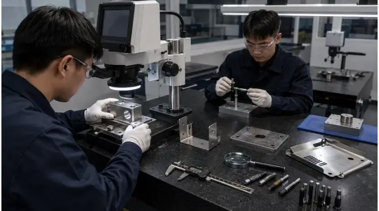
Tolerances, Surfaces, and Downstream Processes
The deburring process must never compromise the functional dimensions of the workpiece. After deburring, QA teams must re-verify specific features that are highly susceptible to secondary processing damage:
- Critical hole diameters and thread entries.
- Mounting holes for PEM hardware or press-fit inserts (Over-deburring these holes causes fasteners to spin or pull out under torque).
- Thin walls and narrow bridge sections.
- Sealing faces and overall flatness.
- Specified chamfer or radius dimensions.
Engineers must also evaluate how the deburring method affects downstream processes. Common hidden risks include:
- Grinding dust contaminating pre-paint chemical wash lines.
- Abrasive media trapped inside blind holes, hems, or manifolds.
- New scratches introduced to cosmetic surfaces during batch tumbling.
- Sharp edges causing paint or powder coat to pull away, leaving thin, unprotected coverage.
- Loose metal particles migrating into hydraulic seals or motion systems.
- Over-radiused edges destroying precise part fitment or welding gaps.
The Definition of Done
Deburring is complete only when the part is clean, dimensionally acceptable, and ready for the next process.
Drawing Notes and Critical Edges
Vague drawing notes are a primary source of manufacturing disputes. Engineers must explicitly define what is required using standard terminology:
- Remove loose burrs: Clears debris and hanging fragments but leaves the underlying edge geometry largely intact.
- Break all sharp edges: Generally implies a minimal corner break (e.g., a light tumble or manual file swipe) to ensure safe handling.
- Maximum burr height: Allows a burr up to a measured tolerance limit (frequently used in non-critical sheet metal stamping).
- Defined chamfer / edge radius: Requires specific geometry (e.g., 0.5 mm ± 0.1) that must be machined and measured.
- Keep edge sharp / Do not break edge: Strictly forbids mechanical deburring on functional edges, such as cutting blades or flush-mating datum faces. This often requires the shop to design custom masking fixtures before tumbling or blasting.
To prevent costly rework, drawings must visually distinguish between general edges, exposed safety edges, mating components, sealing faces, hole exits, cosmetic edges, and “do not break” zones. Never rely on a supplier’s internal “shop default” as a universal standard. If an edge is critical to the assembly, it requires explicit dimensions, tolerances, or a physical limit sample approved by both parties.
Conclusion
Deburring is not just a final cleanup step. The correct method depends on the burr location, material, part geometry, surface finish, and required edge condition. Clear drawing notes and first-article inspection can prevent poor fit, damaged coatings, loose particles, and unnecessary manual work.
If your CNC-machined or sheet metal part needs controlled edge quality, send us your 2D drawings or 3D models. Include the material, quantity, critical edges, and finishing requirements. Our engineers will review burr-prone features, recommend a practical deburring approach, and prepare a manufacturing quote.