Notice: Function _load_textdomain_just_in_time was called incorrectly. Translation loading for the acf domain was triggered too early. This is usually an indicator for some code in the plugin or theme running too early. Translations should be loaded at the init action or later. Please see Debugging in WordPress for more information. (This message was added in version 6.7.0.) in /home/u505400276/domains/tzrmetal.com/public_html/wp-includes/functions.php on line 6131

Notice: Function _load_textdomain_just_in_time was called incorrectly. Translation loading for the unlimited-elements-for-elementor domain was triggered too early. This is usually an indicator for some code in the plugin or theme running too early. Translations should be loaded at the init action or later. Please see Debugging in WordPress for more information. (This message was added in version 6.7.0.) in /home/u505400276/domains/tzrmetal.com/public_html/wp-includes/functions.php on line 6131

Notice: Function _load_textdomain_just_in_time was called incorrectly. Translation loading for the wordpress-seo domain was triggered too early. This is usually an indicator for some code in the plugin or theme running too early. Translations should be loaded at the init action or later. Please see Debugging in WordPress for more information. (This message was added in version 6.7.0.) in /home/u505400276/domains/tzrmetal.com/public_html/wp-includes/functions.php on line 6131

Notice: Function _load_textdomain_just_in_time was called incorrectly. Translation loading for the simple-history domain was triggered too early. This is usually an indicator for some code in the plugin or theme running too early. Translations should be loaded at the init action or later. Please see Debugging in WordPress for more information. (This message was added in version 6.7.0.) in /home/u505400276/domains/tzrmetal.com/public_html/wp-includes/functions.php on line 6131
Kevin, Author at TZR Sheet Metal

Author: Kevin

  • What Is Sheet Metal Punching? Process, Applications , and Engineering Insights

    What Is Sheet Metal Punching? Process, Applications , and Engineering Insights

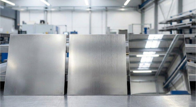
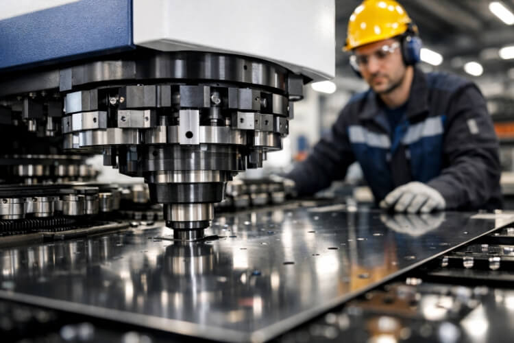
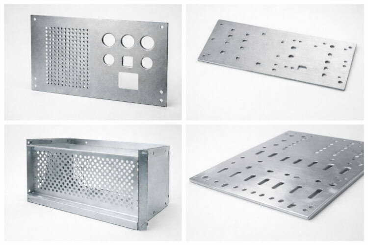
    Every sheet metal factory depends on one process more than any other — punching. It is used for many purposes, such as making ventilation holes in EV battery enclosures, mounting slots for control panels, or fastener patterns for industrial frames. Metal punching provides fast, accurate results at a low cost.

    At its core, punching uses a hardened punch and die set to apply force to a flat metal sheet. When this force is greater than the material’s shear strength, the metal breaks cleanly, forming a hole or cutout of the desired shape.

    Even though laser and waterjet cutting are becoming more common, punching remains the most efficient option for high-volume fabrication. It offers excellent repeatability, a low cost per part, and well fits bending, forming, and welding operations on the shop floor.

    For engineers and designers, understanding how punching works is key to achieving accurate, clean edges and long tool life. Tool clearance, force calculation, and press alignment all play a significant role in the final result.

    What Is Sheet Metal Punching

    How the Sheet Metal Punching Process Works?

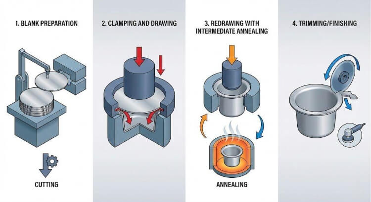
    Sheet metal punching is a controlled shearing process between a punch and a die. The sheet is clamped firmly, and the press delivers a single stroke that cuts through the metal. Each stroke creates a hole in the workpiece and a slug (the removed piece). Accuracy depends on tool sharpness, clearance, and press alignment.

    Step-by-Step Cycle

    1. Clamping and Positioning — The sheet is moved into position and clamped tightly.
    2. Punch Stroke — The punch moves down and presses the metal into the die opening.
    3. Elastic and Plastic Deformation — The metal first bends slightly, then shears once stress passes its yield point.
    4. Fracture and Ejection — The material separates cleanly. The slug drops through the die, and the punch retracts for the next stroke.

    A punched edge shows four zones — rollover, burnish, fracture, and burr. Adjusting the clearance between the punch and die helps reduce burrs and create a smoother edge.

    Process Variations

    File could not be opened. Check the file’s permissions to make sure it’s readable by your server.

    Each operation serves a specific purpose — for ventilation, mounting, or light-weighting. Many press setups can combine several actions into one stroke to improve efficiency.

    Equipment Used in Metal Punching

    The right combination of machine and tooling makes punching efficient and reliable. The type of press determines speed, accuracy, and tool life.

    Mechanical Press

    A mechanical press uses a flywheel-and-crank system to deliver swift strokes—typically 200 to 600 per minute. It is ideal for thin sheet metal and large production runs. The motion is precise and consistent, though stroke length and force are fixed.

    Hydraulic Press

    A hydraulic press uses fluid pressure to push a piston, applying a steady force throughout the stroke. It works well for thicker materials or combined forming and piercing. It is slower than a mechanical press but gives better depth control and less vibration.
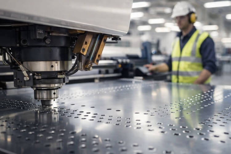
    CNC Turret Press

    Modern workshops often use CNC punching machines for flexible, high-precision work. A rotating turret holds many punches and die sets, allowing automatic tool changes and computer-controlled movement. These machines can handle sheets up to 6 mm thick and arrange multiple parts on a single sheet to save material.

    Material Considerations — Behavior Under Shear

    Different metals react differently to punching. Key factors include ductility, hardness, and grain direction. Knowing these helps engineers pick the right tonnage, clearance, and tool material.

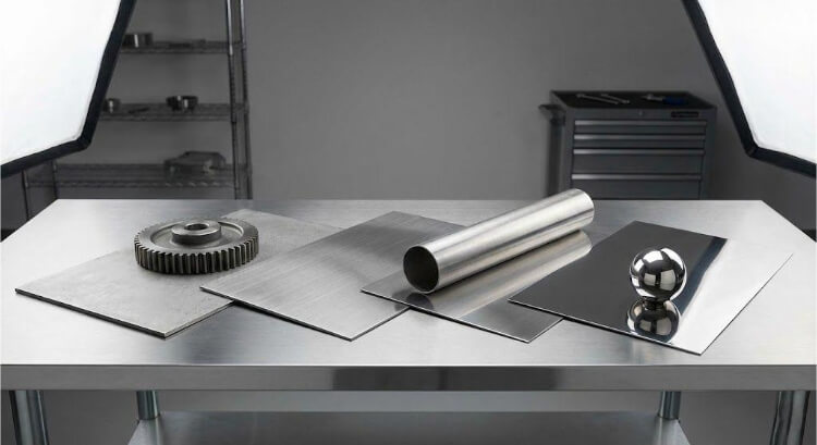
    Commonly Punched Metals

    File could not be opened. Check the file’s permissions to make sure it’s readable by your server.

    Force and Shear Example

    The punching force (F) can be found using:

    F=L×T×τ

    Where L = perimeter (mm), T = thickness (mm), and τ = material shear strength (MPa)

    Example: punching a 10 mm hole in 1 mm stainless steel (τ ≈ 450 MPa):

    F = π × 10 mm × 1 mm × 450 MPa ≈ 14 kN (1.4 tons).

    Engineers often add a 1.2–1.4× safety factor to handle variation and wear.

    Material Edge Behavior

    During punching, the sheet goes through three stages:

    1. Elastic deformation – the sheet bends under pressure.
    2. Plastic flow – metal begins to shear along the punch edge.
    3. Fracture propagation – cracks spread and the cut completes.

    The cut edge usually has four zones: rollover, burnish, fracture, and burr. Reasonable clearance control reduces the fracture area, and proper lubrication helps lower burr height.

    Some advanced systems use micro-lubrication or nitrogen cooling to control heat during continuous punching. This is especially useful when working with aluminum or stainless steel.

    Design and Engineering Guidelines — Building for Manufacturability

    Good design reduces tool wear and improves punching speed. Considering spacing, hole size, and shape early in the CAD stage helps lower production costs.

    Hole Shape and Minimum Size

    Round holes punch cleanly because stress spreads evenly. Non-round shapes focus stress on corners, wearing out tools faster.

    To improve performance:

    • Use fillet radii ≥ 1.5× thickness.
    • Avoid sharp internal angles (<90°).
    • For holes smaller than the sheet thickness, use pilot punching, then ream for roundness.

    Hole Spacing and Edge Distance

    Each punched hole weakens the material around it. Keep spacing at least 2× thickness between holes and from hole to edge. For a 1.5 mm sheet, spacing should be at least 3 mm. This prevents cracks and helps maintain flatness.

    File could not be opened. Check the file’s permissions to make sure it’s readable by your server.

    Tolerance and Quality Control — Maintaining Accuracy at Production Speed

    Precision in sheet metal punching depends on control, not power alone. A well-tuned press, sharp tools, and steady material feeding all ensure repeatable accuracy.

    Dimensional Tolerance

    Modern CNC punching machines can hold ±0.1 mm tolerance on thin sheets and ±0.2 mm on thicker ones. Several factors influence tolerance stability:

    • Tool wear: dull punches cause hole size variation and larger burrs.
    • Material springback: harder metals slightly recover their shape after punching.
    • Machine alignment: even a 0.05 mm offset between punch and die can change the final result.

    Regular calibration keeps machines consistent. Using CMMs or laser alignment systems helps verify accuracy. When very tight fits are required, engineers often perform a secondary reaming or laser trimming to fine-tune dimensions.

    Burr Height and Surface Condition

    Burr height is a quick and reliable measure of tool condition. In stable production, burr height should be less than 10% of the sheet thickness. If it exceeds that limit, it usually means clearance is too wide, the punch is dull, or lubrication is poor.

    To maintain surface quality:

    • Apply steady lubrication to reduce friction.
    • Clean sheets before punching to prevent surface marks.
    • Track burr height trends to plan tool maintenance early.

    Reducing Material Waste — Smart Nesting and Sheet Utilization

    Efficient material use directly improves profit. In sheet-metal punching, intelligent nesting helps maximize yield from each sheet and reduce scrap.

    CNC Nesting Optimization

    Modern CNC punching software automatically arranges parts to optimize material use. It simulates punch travel paths, reduces idle moves, and improves sheet utilization. A well-planned nesting layout can improve material yield by 15–25% compared with manual setups.

    Engineers also use common-line punching, in which two parts share a single punched edge. This method saves material and tooling effort, though it requires precise alignment to avoid overlap or gaps.

    Scrap Management and Reuse

    Even efficient layouts produce slugs and offcuts. Sorting valuable materials such as stainless steel, aluminum, and copper enables 80–90% recycling. A conveyor or magnetic collector under the die keeps the workspace clean and prevents slug buildup, which could damage tools.

    Advantages and Limitations of Metal Punching

    Advantages

    1. High Speed and Throughput: Mechanical presses can perform hundreds of strokes per minute, ideal for repetitive hole patterns.
    2. Consistency and Repeatability: Once aligned, each stroke produces identical holes, ensuring accuracy across batches.
    3. Cost Efficiency: Tooling costs are quickly recovered over large volumes, reducing per-part expenses.
    4. Material Versatility: Works well with mild steel, stainless steel, aluminum, brass, and copper within 0.5–6 mm thickness.
    5. Process Integration: Punching can be combined with forming, embossing, tapping, or marking in one operation.

    Limitations

    1. Design Limitations: Each shape requires its own punch and die, increasing lead time for unique designs.
    2. Burr Formation: Even optimized setups leave small burrs that may require finishing.
    3. Thickness Limit: Above 6 mm, punching efficiency drops; laser or plasma cutting works better.
    4. Noise and Vibration: Mechanical presses produce loud impacts, often needing soundproof enclosures.
    5. Setup Time for Small Runs: For short batches or prototypes, setup time can outweigh production speed benefits.

    Comparison with Other Cutting Methods

    The best cutting method depends on part design, thickness, and quantity. Here’s how punching compares with laser and waterjet cutting:

    File could not be opened. Check the file’s permissions to make sure it’s readable by your server.

    Practical Applications of Metal Punching in Modern Manufacturing

    The sheet-metal punching process is a key operation in many industries that require precise, repeatable metal parts. Its speed, accuracy, and versatility make it one of the most reliable fabrication methods today.

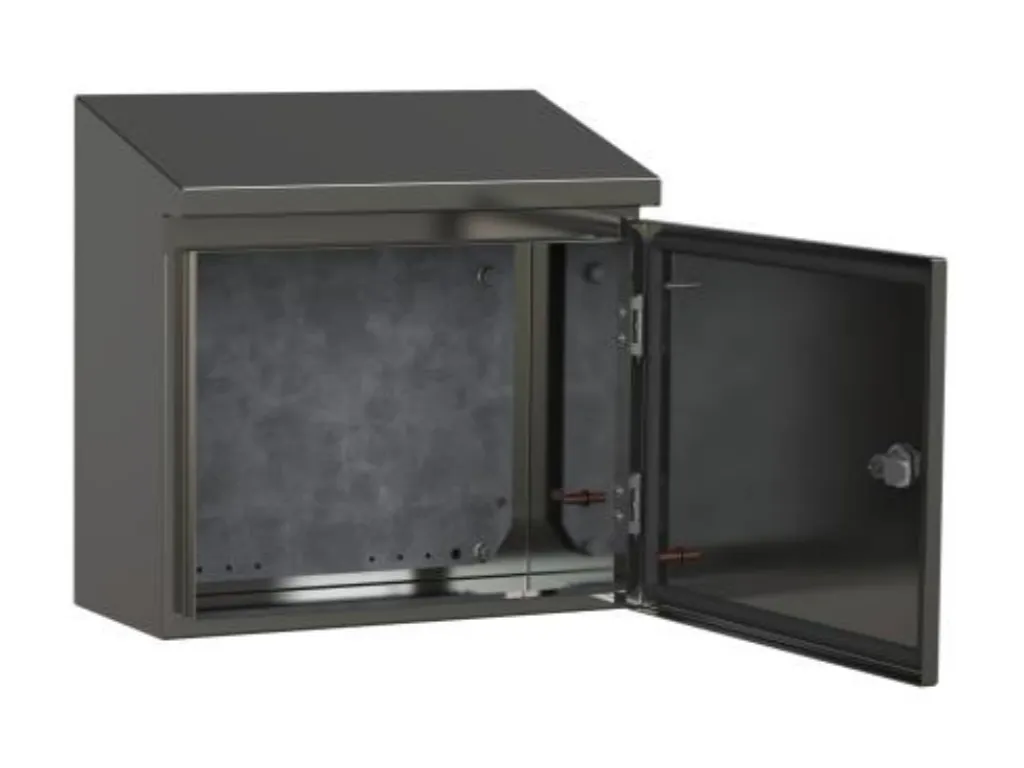
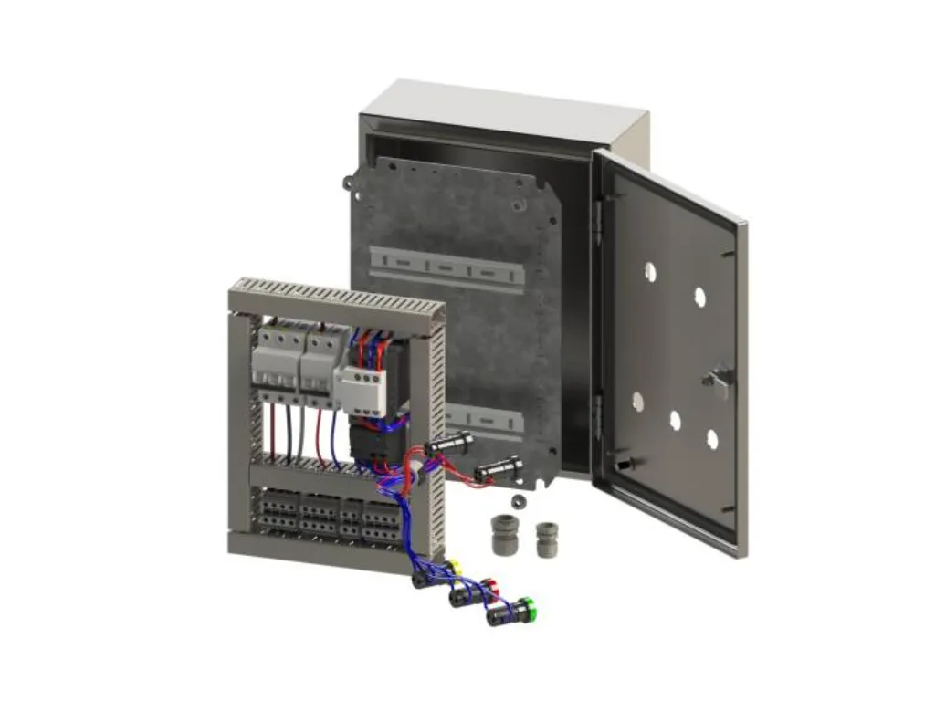
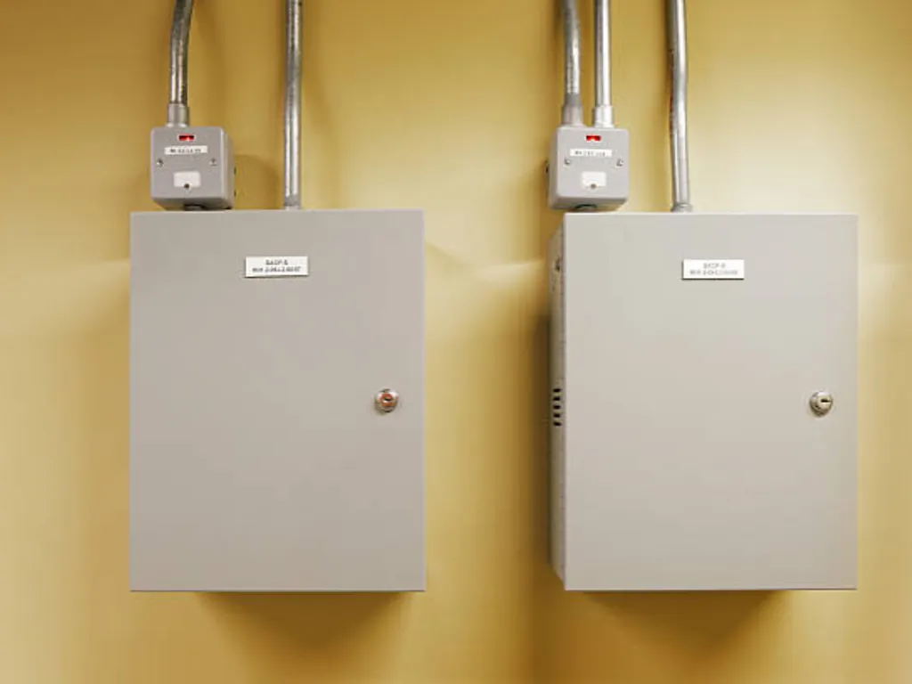
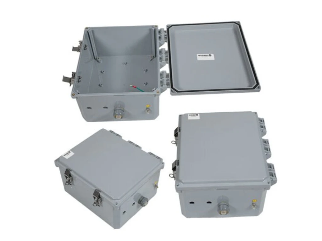
    Electronics and Electrical Enclosures

    CNC punching is used to make panels, housings, and covers for electrical and electronic products. It allows fast creation of ventilation holes, cable ports, and mounting slots with tight tolerances. These details are essential for both EMI shielding and smooth assembly.

    Automotive and Transportation

    In automotive manufacturing, punching is used for parts such as brackets, seat frames, battery cases, and reinforcement plates. Because of its high precision, it ensures consistent hole alignment across assemblies, where even a 0.1 mm error can cause misfits.

    HVAC and Appliance Manufacturing

    Air conditioners, refrigerators, and duct systems depend on punching to create airflow holes and mounting points. Using turret presses, factories can produce thousands of metal panels each day with minimal manual setup.

    Industrial Equipment and Machine Frames

    Punching makes base plates, mounting panels, and support structures for machines in the automation and packaging industries. In large assemblies, these punched holes act as reference points for welding, bolting, or mechanical fastening.

    Renewable Energy and Power Systems

    Punching is used in solar panel frames, battery boxes, and wind turbine housings. It ensures a lightweight structure and consistent accuracy, which are vital for parts that face long-term outdoor exposure.

    Metal punching Applications

    Conclusion

    Metal punching has evolved from a manual process to an innovative, data-driven method. Modern CNC presses now use sensors, servo motors, and intelligent control systems to control every stroke precisely.

    This evolution keeps punching among the fastest, most affordable, and most accurate sheet metal cutting processes. It connects traditional manufacturing strength with digital precision — transforming simple holes into key features that define part quality.

    If your project involves precision sheet metal punching, material selection, or small-batch production, our engineering team can help. We review your drawings, calculate proper clearances, and suggest improvements before fabrication. Contact our engineers today to discuss your design.

    FAQs

    What is the primary purpose of metal punching?

    Metal punching forms holes, slots, or shapes in sheet metal using a punch and die. It’s ideal for large production runs that need consistent precision and speed.

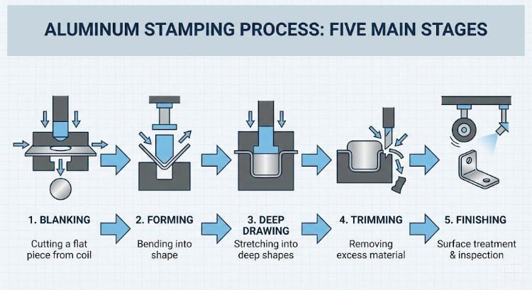
    How is punching different from blanking?

    In punching, the hole is kept, and the slug is wasted. In blanking, the slug becomes the finished part, and the remaining sheet is scrap. Both operations use the same type of press.

    How accurate is CNC punching?

    CNC punching offers ±0.1 mm accuracy for thin sheets and ±0.2 mm for thicker ones. Results depend on tool sharpness, clearance, and press alignment.

    What causes burrs, and how can they be minimized?

    Burrs form from worn tools or incorrect clearance. Following proper clearance rules (5–10% of sheet thickness), using lubrication, and regular sharpening help reduce burrs.

  • Stainless Steel Finishes: Ra Values, Applications, and Selection Tips

    Stainless Steel Finishes: Ra Values, Applications, and Selection Tips

    In stainless steel fabrication, the surface finish is an engineering decision, not just about looks. It directly affects corrosion resistance, weld quality, and maintenance cost. Many failures, such as rust or cleaning problems, come from using the wrong surface finish, not from choosing the wrong alloy.

    A smoother surface strengthens the protective chromium oxide layer, reducing the risk of corrosion. Rougher surfaces may improve grip or hide scratches, but they also hold dirt and moisture that can damage the metal over time. In sanitary or marine environments, even a 0.2 µm difference in roughness can decide whether a part passes inspection.

    Standards like ASTM A480 and EN 10088 group stainless steel finishes by process and texture. When combined with measurable data such as Ra (roughness average), these standards help ensure consistent quality in global manufacturing.

    Stainless Steel Finishes

    Basics of Stainless Steel Surface Finishes

    Before choosing a finish, it helps to understand how surface texture forms and how it’s measured. Every production step — rolling, annealing, pickling, and polishing — changes the surface at a microscopic level, which affects corrosion resistance.

    How Alloy and Process Shape the Surface?

    The surface of stainless steel shows the story of its production:

    • Hot-rolling produces a coarse surface with scale.
    • Cold rolling smooths the grain and improves thickness control.
    • Annealing relieves stress, and pickling removes oxide layers.
    • Polishing or electropolishing sets the final smoothness, shine, and cleanliness.

    Surface roughness is measured by Ra, in micrometers (µm). A lower Ra means a smoother surface and better corrosion resistance.

    Tests show that lowering roughness from 1.0 µm to 0.3 µm can reduce bacterial buildup by 70–80% and extend corrosion life by 30–40%.

    Finish Classification

    Stainless steel finishes fall into four main categories based on how they’re made and what they’re used for.

    File could not be opened. Check the file’s permissions to make sure it’s readable by your server.

    Codes such as ASTM No. 4 or EN 2G, along with grit size and Ra value, help define the exact surface quality. Avoid unclear terms such as “smooth” or “mirror” in engineering drawings.

    Mill Finishes: Practical Surfaces from the Mill

    Mill finishes come straight from the mill after rolling and pickling. They serve as the basis for many later finishing steps.

    No. 1 – Hot Rolled, Annealed, and Pickled

    Process: Hot rolling → annealing → pickling

    Appearance: Dull matte with heavy grain

    Typical Ra: 3.0–7.5 µm

    This rough, non-reflective surface is suitable for furnace parts, pressure vessels, and heavy machinery. It handles high heat well but isn’t meant for appearance.

    Engineering takeaway: Use No. 1 when you care about strength and durability more than looks.

    No. 2D – Cold Rolled, Annealed, and Pickled

    Process: Cold rolling → annealing → pickling

    Appearance: Dull gray with even texture

    Typical Ra: 0.8–1.6 µm

    No. 2D is smoother and more consistent than No. 1. It offers better forming ability and thickness control, making it suitable for industrial housings, tanks, and enclosures. It also works well as a base for later polishing or coating.

    No. 2B – Bright Cold Rolled Finish

    Process: Cold rolling → annealing → skin-pass on polished rolls

    Appearance: Smooth and lightly reflective

    Typical Ra: 0.2–0.5 µm

    No. 2B is the most common mill finish in the stainless steel industry. It provides good corrosion resistance, easy cleaning, and moderate shine. It’s often used for kitchen tools, chemical tanks, and panel work, and it serves as the base for finishes like No. 4 or No. 8.

    Mill Finish Comparison

    File could not be opened. Check the file’s permissions to make sure it’s readable by your server.

    Mechanically Polished and Decorative Finishes

    After the mill process, mechanical finishing defines how stainless steel looks, feels, and performs. Grinding, brushing, and buffing create specific surface textures measured by Ra (roughness average).

    Mechanically Polished Finishes

    No. 3 – Coarse Polished Finish

    Process: Ground with 100–120 grit abrasives

    Appearance: Coarse, visible grain pattern

    Typical Ra: 0.8–1.0 µm

    No. 3 has a brushed texture that hides fingerprints and scratches. It’s used in industrial interiors, kitchen tools, and transport panels. It’s not very reflective but is durable and works well as a base finish for further polishing.

    No. 4 – Brushed or Satin Finish

    Process: Refined with 150–180 grit abrasives

    Appearance: Smooth, satin-like with an apparent grain

    Typical Ra: 0.4–0.6 µm

    No. 4 is the most widely used finish for architecture and appliances. It’s common in elevators, kitchen fixtures, wall panels, and enclosures. The surface is easy to clean, looks professional, and can be repaired if scratched.

    No. 6 – Fine Satin Finish

    Process: Polished with finer abrasives or non-woven pads

    Appearance: Soft gloss with less visible grain

    Typical Ra: 0.2–0.3 µm

    No. 6 provides a smooth, semi-reflective surface that feels pleasant to touch. It’s often used in handrails, control panels, and decorative interiors where soft light reflection is desired.

    No. 8 – Mirror Finish

    Process: Multi-stage polishing and buffing

    Appearance: Bright, mirror-like reflection

    Typical Ra: ≤0.1 µm

    No. 8 has the smoothest, shiniest finish. It’s used in luxury architecture, medical tools, and cleanroom equipment. While it resists corrosion very well, it shows fingerprints easily and needs regular cleaning.

    Mechanically Polished Finishes

    Comparison of Mechanically Polished Finishes

    File could not be opened. Check the file’s permissions to make sure it’s readable by your server.

    Special and Decorative Finishes

    Modern stainless steel often serves both mechanical and visual purposes. Decorative finishes bring design creativity into engineering, improving appearance and durability simultaneously.

    Patterned and Textured Surfaces

    Process: Embossed or rolled with patterned rollers

    Ra: 0.6–1.2 µm

    These surfaces create three-dimensional patterns that hide wear, reduce glare, and increase stiffness. Common patterns include linen, diamond, quilted, and leather grain. They’re used in elevators, transport interiors, and architectural façades.

    Bead-Blasted and Sand-Blasted Finishes

    Process: Blasting with glass beads or sand particles

    Ra: 0.8–1.0 µm

    Appearance: Smooth, uniform matte tone

    Bead blasting gives a soft, non-directional look, evenly spreading light. It’s often used in machinery covers, housings, and industrial panels. Clean blasting is essential — leftover particles can harm corrosion resistance.

    Electropolished Surfaces

    Process: Electrochemical removal of surface metal

    Ra: ≤0.2 µm

    Appearance: Bright and smooth

    Electropolishing removes microscopic peaks and contaminants, leaving a pure and corrosion-resistant surface. It’s the top choice for sanitary tubing, food processing, and medical systems.

    Colored Stainless Steel Finishes

    Process: Controlled oxide growth or PVD coating

    Colors: Gold, bronze, black, blue, green

    Ra: Depends on base polish

    Colored finishes add style and brand identity without losing corrosion protection. The colors form from thin oxide layers that reflect light differently, not from paint or pigments. They’re used in signage, modern interiors, and architectural walls.

    Colored Stainless Steel Finishes

    Summary of Decorative Finishes

    File could not be opened. Check the file’s permissions to make sure it’s readable by your server.

    Functional Impact of Stainless Steel Finishes

    A stainless steel surface directly affects how the material behaves in use. Smoother finishes improve corrosion resistance and cleaning, while rougher ones offer better grip or hide wear marks.

    Corrosion Resistance and Cleanability

    Stainless steel’s corrosion resistance comes from the passive chromium oxide layer on its surface. This layer becomes stronger and more stable on smoother finishes.

    When roughness (Ra) drops from 1.0 µm to 0.3 µm, the number of small surface pits decreases sharply. According to Corrosion Science (2022), smoother finishes can delay pitting corrosion by up to 40% in chloride-rich conditions.

    File could not be opened. Check the file’s permissions to make sure it’s readable by your server.

    Finishes such as 2B, No. 4, and electropolished are preferred in hygiene-sensitive industries, such as food, medical, and pharmaceutical production. Directional finishes like No. 4 are easier to clean along the grain, while matte surfaces like bead-blasted finishes require more frequent maintenance.

    Weldability and Post-Weld Surface Treatment

    Welding changes both the chemistry and structure of stainless steel at the joint. Heat reduces chromium at the surface, temporarily weakening corrosion protection. That’s why post-weld cleaning and treatment are needed to restore complete resistance.

    Common recovery steps include:

    1. Pickling: Removes heat tint and scale.
    2. Passivation: Rebuilds the chromium oxide layer.
    3. Mechanical blending: Matches the surface grain and gloss.

    Finishes like 2B and No.4 are easier to restore after welding. Mirror finishes (No. 8) require careful polishing to prevent uneven shine.

    Surface Durability and Maintenance

    Every finish reacts differently over time. All stainless steels resist corrosion, but texture and Ra value control how quickly they collect dirt or scratches.

    • Mirror finishes (No. 8): Great corrosion resistance, but fingerprints show easily.
    • Brushed finishes (No. 4–No. 6): Hide wear marks better and require less cleaning.
    • Electropolished: Offer the best long-term performance in harsh or sterile settings.

    A 2023 Stainless Steel World study found that surfaces with Ra ≤ 0.3 µm lasted over 1,000 hours in salt spray tests, while rougher surfaces with Ra> 1.0 µm showed rust after 400 hours.

    Maintenance best practices:

    • Use mild or neutral cleaners.
    • Avoid carbon steel brushes or tools.
    • Rinse well and dry thoroughly after washing.

    Aesthetic and Functional Stability Over Time

    Finishes change slowly with use and exposure.

    • Brushed textures become shinier from frequent touch.
    • Matte surfaces can dull over time or accumulate dust.
    • Colored or PVD finishes retain their color for years but require gentle cleaning to prevent scratches.

    These changes are expected and can be controlled.

    Choosing the correct grain direction and cleaning method helps the finish keep its intended look.

    Quantitative Surface Roughness Reference

    Ra measures microscopic peaks and valleys on a surface, shown in micrometers (µm). Lower Ra values mean smoother, more reflective, and easier-to-clean surfaces.

    File could not be opened. Check the file’s permissions to make sure it’s readable by your server.

    A lower Ra doesn’t always mean it’s the best choice.

    For instance:

    • Decorative use: No.4 gives a balanced, elegant look.
    • Industrial use: 2B or 2D performs well at low cost.
    • Sanitary use: Electropolished (Ra ≤ 0.2 µm) ensures top hygiene.

    Selecting the Right Stainless Steel Finish

    A stainless steel finish determines how your product performs in the real world. Selecting the right finish prevents over-engineering, avoids early wear, and lowers total upkeep cost.

    By Function and Environment

    Every environment has different performance demands. The table below shows which finishes fit best for each use case:

    File could not be opened. Check the file’s permissions to make sure it’s readable by your server.

    For industrial parts, finishes such as No. 1 or 2D provide strength and reliability at a lower cost. For clean or medical environments, smoother surfaces (Ra ≤ 0.4 µm) maintain hygiene and reduce contamination risk. For architectural use, brushed and mirror finishes combine visual appeal with long-term protection.

    By Cost and Manufacturability

    Each polishing step increases both quality and cost. Finer textures take more time and labor, so applying them only where needed saves money.

    Approximate cost increase over a standard 2B base:

    • No. 4: +20–30%
    • No. 6: +50%
    • No. 8 or PVD colored: +200–300%

    The best strategy is “finish where it matters.” Use high-end finishes only on visible or hygiene-critical areas, keeping hidden surfaces at mill or 2B levels.

    File could not be opened. Check the file’s permissions to make sure it’s readable by your server.

    By Inspection and Specification Standards

    Clear definitions ensure consistent finish quality between suppliers. Vague terms like “polished surface” often lead to inconsistent results or mismatched texture.

    To avoid that, specify finishes by process, grit, and roughness:

    File could not be opened. Check the file’s permissions to make sure it’s readable by your server.

    Adding these details to drawings helps ensure identical finishes in production. Use tools such as profilometers or gloss meters to verify texture, and include sample coupons for reference during RFQ review.

    Conclusion

    A stainless steel finish is more than a cosmetic choice — it’s a functional design decision. It defines how metal interacts with its surroundings, how long it lasts, and how it looks to end users. Specifying finishes with clear parameters — such as Ra, grit, and surface codes — ensures consistent results, predictable performance, and lower maintenance.

    Ready to define your next stainless steel project? Our engineering team can help you evaluate finish performance, cost, and manufacturability — from design to production. Contact us today to discuss your surface finishing needs.

    FAQs

    What’s the most common stainless steel finish?

    The No. 4 brushed finish. It offers the best balance between cost, corrosion resistance, and appearance for most industrial and architectural uses.

    Does surface finish affect corrosion resistance?

    Yes. Smoother finishes below Ra 0.5 µm resist corrosion and contamination better. Electropolished and No. 4 finishes outperform rough mill surfaces in marine or chemical settings.

    Which finishes are easiest to clean?

    2B, No. 8, and electropolished finishes. Their smooth texture limits dirt buildup and allows fast sanitization, making them ideal for food and pharmaceutical use.

    How should I specify finishes in technical drawings?

    Include the following:

    1. Finish code (ASTM / EN)
    2. Grit size
    3. Target Ra value
    4. Grain direction
    5. Any post-treatment

    This ensures production and inspection consistency.

    Is a mirror finish suitable for outdoor use?

    Yes, but it needs regular cleaning. Mirror surfaces resist corrosion well but are prone to smudging. For easier maintenance outdoors, polished or electropolished finishes (Ra ≤ 0.3 µm) are good alternatives.

  • What Is the Deep Drawing Process:Process, Steps, and Benefits

    What Is the Deep Drawing Process:Process, Steps, and Benefits

    Every time you open a car door, twist a fuel cap, or use a stainless-steel sink, you’re handling a deep-drawn part. Deep drawing is one of the most dependable ways to shape sheet metal into seamless, durable forms — from small electrical housings to large structural panels.

    This process turns a flat metal blank into a hollow shape by pulling it into a die cavity with a punch. When the depth of the part is greater than its diameter, it’s called deep drawing. Unlike regular stamping, which mainly cuts or bends metal, deep drawing stretches the sheet to create a smooth, continuous, and joint-free shape that is both light and strong.

    In car manufacturing alone, more than 150 components are deep drawn — such as airbag housings, filters, and fuel covers. The process is favored for its precision, consistency, and high material efficiency, making it essential for scalable and cost-effective production.

    What is Deep Drawing

    What is Deep Drawing?

    Deep drawing is a process of controlled metal flow. A flat blank is held between the die and blank holder while a punch pulls it into the die cavity. During this motion, the metal stretches along the wall and compresses at the flange. Keeping the right balance between tension and compression ensures smooth forming — too little balance leads to wrinkles or tears.

    Modern servo and hydraulic presses monitor punch position and forming force during each stroke. The force–displacement curve they record shows flow stability: a smooth curve means even deformation, while sudden spikes often indicate friction or lubrication problems.

    Essential Components and Their Roles

    File could not be opened. Check the file’s permissions to make sure it’s readable by your server.

    These parts must align perfectly and have smooth surfaces. Even a 0.05 mm offset can cause uneven wall thickness or edge distortion.

    Typical Applications

    Deep drawing is common wherever seamless surfaces and strong geometry matter:

      • Automotive: fuel tanks, filter shells, sensor housings

      • Electronics: enclosures, EMI shields, connector caps

      • Appliances: sinks, cookware, light fixtures

      • Medical & Industrial: housings, pump cases, precision containers

    This method combines repeatable quality with minimal waste, making it ideal for long production runs.

    How Does Deep Drawing works:Step by Step

    Each forming stage serves a purpose. When tuned properly, the sequence ensures smooth flow, accuracy, and long tool life.

    Step 1:Blank Preparation

    The process starts by cutting blanks from sheet or coil stock, usually mild steel, stainless steel, or aluminum. Precise cutting with lasers or shears gives clean edges that prevent cracks during forming.

    Next, the blanks are cleaned and lubricated. A consistent layer of oil or polymer film lowers friction and ensures balanced flow. Uneven coating can cause one side to stretch faster than the other.

    Step :2:Clamping and Initial Drawing

    The blank is clamped between the die and blank holder under controlled pressure. As the punch descends, it pulls the sheet into the die. The flange compresses, and the wall stretches — both must stay in balance for smooth forming.

    Key settings include:

      • Blank-holder pressure: too low causes wrinkles; too high causes tearing.

      • Punch speed: slower at the bottom stroke helps avoid strain buildup.

      • Lubrication: must stay stable, with friction between 0.05–0.10 for steel.

    For mild steel, the best drawing ratio (blank diameter ÷ punch diameter) is 1.8–2.2. Higher values require redrawing.

    Step 3:Redrawing and Intermediate Annealing

    If one draw cannot reach the required depth, engineers use several drawing stages. Each stage deepens the part gradually to prevent excessive thinning. Between stages, annealing restores ductility lost from work hardening — usually 600 °C for steel and 350 °C for aluminum.

    This balance between forming and heat treatment prevents cracks and improves surface finish.

    Step 4:Trimming and Finishing

    After the final draw, the flange is trimmed for even height. Laser or CNC trimming reaches ±0.05 mm accuracy. The part is then cleaned, deburred, or polished, depending on its use.

    For precision items like sensor housings or pump covers, CMM inspection checks roundness and wall accuracy within ±0.1 mm along the full height. At this stage, the once-flat blank has become a strong, uniform, and ready-to-assemble component — made without welding or extra machining.

    How Does Deep Drawing works

    Materials and Formability Considerations

    Material selection determines whether a sheet forms smoothly or cracks during drawing. The best materials for deep drawing have high ductility, low yield strength, and fine, uniform grains.

    Common Materials Used in Deep Drawing

    File could not be opened. Check the file’s permissions to make sure it’s readable by your server.

    Elongation measures how far a sheet can stretch before it breaks. n-value shows how evenly the material thins under tension. A higher n-value means smoother walls and fewer thin spots.

    Engineer Insight:
    Stainless steel 304 with 40% elongation can reach a draw ratio of around 2.0 : 1 in one pass. Aluminum 6061-T6, which is harder, usually needs an annealing step at about 350 °C to prevent cracking.

    Key Mechanical Properties to Check

    • Yield-to-Tensile Ratio: Around 0.6 provides enough stretch without losing strength.
    • Anisotropy (r-Value): Values above 1.5 reduce earing and keep the wall height uniform.
    • Thickness Variation: Even ±0.02 mm changes can shift stress and cause waviness.

    Tests like Erichsen cupping or Limiting Drawing Ratio (LDR) help confirm if the sheet can handle the required depth safely.

    Formability Trade-Offs

    • Steel forms steadily and resists defects but needs 25–40% more press force than aluminum.
    • Aluminum is lighter and forms quickly but sticks easily and needs special lubricants.
    • Copper and brass form cleanly but harden fast, so they need frequent annealing between draws.

    Design and Engineering Parameters

    Even a good material can fail if the design ignores forming limits. Proper geometry, clearance, and friction control make deep drawing consistent and predictable.

    Critical Geometry Ratios

    • Drawing Ratio (DR) = Blank Diameter ÷ Punch Diameter
      • Safe range for most steels: 1.8–2.2
      • Beyond 2.3 → requires redrawing in multiple stages
    • Limiting Drawing Ratio (LDR): The maximum safe ratio before failure.
      • Mild Steel ≈ 2.2 Al 5052 ≈ 1.9 Stainless 304 ≈ 1.8

    Example:
    Raising the DR from 1.8 to 2.0 increases press force by about 15%. Using a low-friction lubricant (μ ≈ 0.06) can offset the higher load and keep wall thinning under 15%.

    Tool Geometry and Clearance

    File could not be opened. Check the file’s permissions to make sure it’s readable by your server.

    Even a 1 mm larger die radius can cut edge thinning by 20–25%, which greatly extends tool life during high-volume runs.

    Friction and Lubrication Control

    Friction defines how metal slides in the die. The goal is smooth, steady motion.

    • Steel: Use synthetic ester or graphite-based lubricants.
    • Aluminum: Use PTFE or polymer films to avoid galling.
    • Surface Finish: Ra 0.2–0.4 µm provides good grip and consistent sliding.

    Uneven surface roughness or poor lubrication can cause tearing or uneven wall thickness.

    Dimensional Accuracy and Tolerancing

    Deep-drawn parts often hold ± 0.05 mm in wall thickness and ± 0.1 mm in height after trimming. Servo presses with real-time sensors adjust pressure and speed during every stroke to keep parts consistent through long production runs.

    Preventing Common Defects

    Even with careful setup, issues like wrinkling, tearing, or earing can appear. Understanding these problems helps engineers prevent downtime and scrap.

    Wrinkling

    Wrinkles appear when the flange area compresses too much.

    • Causes: Low blank-holder pressure, too much lubricant, or oversized blanks.
    • Solutions: Increase holder pressure 10–15%, add draw beads, or use stepped dies.

    Tight pressure control can reduce visible wrinkles by up to 60% and improve surface flatness.

    Tearing and Cracking

    Tears occur when tensile stress exceeds the material’s limit, usually near the punch radius.

    • Causes: Sharp corners, poor lubrication, or high punch speed.
    • Fixes: Polish tool edges, use stronger lubricants, and slow down near the end of the stroke.

    Engineer Insight:
    Slowing the final 20% of stroke in aluminum 5052 can cut tearing rates by about one-third.

    Earing

    “Ears” are small rim peaks caused by uneven grain flow during forming.

    • Causes: Anisotropy from rolling direction.
    • Solutions: Rotate blanks 45° relative to the grain, choose materials with higher r-values, or trim extra height during finishing.

    Modern vision systems can measure ear height within ± 0.1 mm and automatically adjust blank orientation for the next cycle.

    Advantages of Deep Drawing

    Deep drawing remains one of the most reliable ways to form sheet metal into strong, seamless, and consistent shapes at scale. Its benefits cover strength, cost, accuracy, and appearance — all while supporting sustainable, high-volume production.

    Seamless Strength and Durability

    Each deep-drawn part starts as one solid sheet, which means there are no welds or joints that could fail.
    This uninterrupted grain structure increases strength and fatigue resistance, making it ideal for automotive housings, hydraulic parts, and pressure containers.

    Tests show that deep-drawn low-carbon steel cups can handle 15–20% higher internal pressure than welded parts of the same thickness, proving their superior reliability.

    High Accuracy and Repeatability

    Modern servo presses control force and position within microns. Once setup is complete, the process repeats with near-perfect consistency. A 200-ton servo press can make over 50,000 identical enclosures before the dies need re-polishing. Sensors constantly track forming force and alignment to maintain quality.

    Lower Cost and Material Waste

    Deep drawing converts almost the entire blank into a finished part, leaving very little scrap. Each stroke takes only 1–3 seconds, which keeps output high and costs low.

    Compared with machining or spinning, deep drawing can:

    • Reduce raw-material waste by 80–90%
    • Lower cost per part by 30–50% in volume production
    • Remove the need for welding or secondary assembly

    Excellent Surface Finish

    As the metal flows across polished tooling, it develops a smooth, reflective surface.
    Typical finishes reach Ra 0.2–0.4 µm, which is clean enough for direct use in kitchenware, lighting, and medical parts without further polishing.

    This natural finish not only saves time but also enhances corrosion resistance and visual quality.

    Flexible Design Across Industries

    Deep drawing handles round, rectangular, and complex shapes with ease. It’s used across a wide range of sectors:

    • Automotive: fuel caps, filter housings, sensor shells
    • Electronics: EMI shields, connector enclosures
    • Aerospace: precision shells, protective covers
    • Consumer Goods: cookware, appliance panels

    Because it scales easily from prototype to full production, deep drawing supports both custom designs and mass manufacturing efficiently.

    Conclusion

    Deep drawing combines material science, tooling design, and precise control to make parts that are lighter, stronger, and consistent in every batch. Modern servo technology and digital monitoring have transformed it into a smart, data-driven process capable of near-zero defects.

    With its mix of efficiency, strength, and cost control, deep drawing remains a cornerstone of modern manufacturing.

    Need help designing or producing deep-drawn metal parts? Our engineering team specializes in precision sheet-metal fabrication — from material selection and tooling design to prototype validation and mass production. Get in touch to discuss your project requirements and receive a fast, detailed quote.

    FAQs

    What makes deep drawing different from stamping?

    Stamping mainly cuts or bends shallow parts, while deep drawing stretches sheet metal into deeper, seamless shapes that offer higher strength.

    Which metals are best for deep drawing?

    Metals with good ductility and balanced strength — such as mild steel, stainless steel 304, and aluminum 5052 — form smoothly and maintain consistent wall thickness.

    How do manufacturers prevent tearing or wrinkling?

    They control blank-holder pressure, draw ratio, and lubrication. Servo presses can automatically adjust these parameters during each stroke to keep the metal flow stable.

    Can deep drawing be used for prototypes or small runs?

    Yes. With soft or modular dies, engineers can quickly test designs before investing in hardened tooling, which helps speed up product development.

    Is deep drawing energy-efficient?

    Yes. Modern servo presses use 30–40% less energy than older mechanical systems. Combined with high material utilization and recyclability, it supports low-carbon, sustainable production.

  • Aluminum Stamping: Process, Alloys & Design Guide for Precision Manufacturing

    Aluminum Stamping: Process, Alloys & Design Guide for Precision Manufacturing

    Aluminum stamping is a key process in modern sheet-metal fabrication. It turns flat aluminum sheets into strong, precise parts with great efficiency. From automotive body panels and battery housings to industrial brackets and electronic frames, aluminum stamping delivers speed, accuracy, and consistency.

    Industry data shows that replacing steel with aluminum can cut a vehicle’s body weight by up to 40%, which can improve fuel economy or EV range by 6–8%. Lightweight design is more than a trend — it’s a smart strategy for energy savings, performance, and sustainability.

    This article explains the basic process, material options, and design practices that help engineers create lighter and smarter products.

    Aluminum stamping press forming automotive brackets

    Understanding Aluminum Stamping

    Aluminum stamping transforms flat sheets into precise, durable components through controlled pressure and tooling. This section explains the core process types and how each achieves accuracy and efficiency.

    What is Aluminum Stamping?

    Aluminum stamping uses a press and die to shape or cut flat aluminum sheets. Each press stroke applies controlled force that reshapes the metal without melting or machining it.

    The main operations include blanking, piercing, bending, and drawing. In large-scale production, progressive dies combine these steps to reach 60–120 strokes per minute while keeping tight tolerances.

    Types of Aluminum Stamping Operations

    Different stamping setups serve different production goals — from simple flat parts to deep, complex housings.

    File could not be opened. Check the file’s permissions to make sure it’s readable by your server.

    Material Characteristics That Influence Stamping

    The behavior of aluminum under pressure determines forming success. Let’s explore why certain alloys, tempers, and surface treatments make all the difference in stamping performance.

    Why Aluminum Is Ideal for Stamping?

    Aluminum combines lightweight strength with good formability, making it excellent for stamping. Its density is only 2.7 g/cm³, about one-third of steel, yet its specific strength stays high. Replacing steel with aluminum can cut weight by up to 40% while keeping rigidity.

    It also forms a thin oxide layer that protects against corrosion. Aluminum’s high thermal and electrical conductivity make it suitable for housings and cooling systems.

    From an environmental view, recycled aluminum keeps over 90% of its original energy value, supporting sustainable production.

    Common Aluminum Alloys Used in Stamping

    Choosing the right alloy balances strength, formability, and cost.

    File could not be opened. Check the file’s permissions to make sure it’s readable by your server.

    Engineer Insight: 5052-H32 gives a great balance — strong for brackets yet soft enough for progressive forming. 6061-T6 needs more tonnage and careful corner radii to prevent edge cracks.

    Material Condition and Surface Treatments

    The temper condition (O, H12, H32, etc.) affects how aluminum behaves during forming. Softer tempers are easier to draw but may warp; harder ones keep shape better but can crack.

    To control friction and extend tool life, many factories use dry-film lubricants or PVD coatings like TiN or CrN. After stamping, parts often get anodized, powder-coated, or conversion-coated for protection and appearance.

    Key Steps in the Aluminum Stamping Process

    Every stage — from blanking to finishing — defines part quality. Here’s how each process step contributes to precision, repeatability, and smooth surface results.

    Blanking and Piercing

    The stamping process starts with blanking, where aluminum sheets are cut into exact shapes using punches and dies. A well-planned nesting layout can raise material use by 15–25%, lowering scrap and total cost.

    Next comes piercing, which adds holes or cutouts. Keeping punch-to-die clearance around 6–10% of sheet thickness helps prevent burrs and tapered edges. During high-speed runs, technicians check punch sharpness and die alignment often.

    Forming and Bending

    After cutting, blanks move to forming presses that shape them into contours or angles. Aluminum tends to spring back slightly toward its flat shape after bending because of its elasticity.

    To counter this, engineers use overbending or modify die geometry. For most alloys, the smallest inside bend radius should be 1.5 × sheet thickness; 6061-T6 may need 2 ×.

    Drawing and Coining

    Deep drawing turns flat blanks into cup- or shell-shaped parts. Smooth radii, steady blank-holder pressure, and consistent lubrication are the main factors that prevent wrinkling or tearing.

    Simulation results show that balancing pressure can cut draw-depth variation by up to 30% compared with manual control.

    Coining is usually the final precision step. It refines edges, flattens surfaces, and improves sealing areas, which is ideal for electronic or fluid-tight enclosures.

    Trimming, Deburring, and Finishing

    Formed parts go through trimming to remove excess metal and deburring to smooth edges. Automated brushing and vibratory finishing help produce uniform results at scale.

    Surface finishing may include anodizing, powder coating, or chemical conversion coating, depending on where the part will be used. These treatments protect against corrosion, improve appearance, or keep electrical conductivity.

    Key Steps in the Aluminum Stamping Process

    Process Challenges and Engineering Considerations

    Even experienced manufacturers face unique challenges with aluminum. The following sections outline common issues and proven strategies for achieving consistent forming results.

    Typical Issues in Aluminum Stamping

    File could not be opened. Check the file’s permissions to make sure it’s readable by your server.

    Strategies to Overcome Defects

    • Improve Die Geometry: Increase fillet radii and polish die corners. Even a 1 mm radius change can extend die life by 25%.
    • Use Proper Lubrication: Apply dry-film lubricants or PVD coatings like TiN or CrN to cut friction.
    • Control Blank-Holder Pressure: Servo systems adjust pressure automatically to keep material flow even.
    • Adjust Temperature: Preheat aluminum to 120–150°C to make hard alloys more formable.
    • Combine Simulation with SPC: Use forming simulation and statistical process control to catch errors early.

    Tolerance and Dimensional Control

    Stamped aluminum parts often hold ±0.05 mm to ±0.10 mm accuracy. To achieve this, presses use real-time force monitoring and regular die calibration.

    Changes in temperature or sheet thickness can slowly shift tolerances. Modern servo presses can automatically adjust shut height and stroke to correct for this, improving yields by up to 40% over manual systems.

    Applications Across Industries

    Aluminum stamping powers innovation across multiple sectors. See how it supports lighter, stronger, and more efficient products from vehicles to aerospace systems.

    Automotive and Electric Vehicle Components

    The automotive and EV sectors depend heavily on aluminum stamping to meet goals for lightweight construction and sustainability. Replacing steel with aluminum can lower total vehicle weight by 15–20%, improving fuel economy by 6–8% and extending EV range by 10–12%.

    Stamped aluminum parts include body panels, battery cases, crash boxes, heat shields, and brackets. These components offer corrosion resistance, strength, and durability, performing reliably even under vibration or thermal cycling.

    Electronics and Consumer Devices

    In electronics, aluminum stamping enables thin, strong, and attractive designs — perfect for laptop frames, LED housings, and communication device enclosures. Its thermal conductivity helps remove heat naturally, reducing the need for extra cooling components.

    Stamped aluminum also provides EMI/RFI shielding, protecting sensitive circuits from electromagnetic interference. Surface finishes like anodizing and conversion coating improve both appearance and corrosion resistance, adding durability to high-end products.

    Aerospace and Industrial Equipment

    In aerospace, aluminum stamping is used for brackets, ducts, mounting plates, and instrument housings. High-strength alloys such as 2024-T3 and 7075-T6 reach tensile strengths above 450 MPa, keeping parts rigid while reducing weight by nearly two-thirds compared to steel.

    Stamped components often receive CNC machining or CMM inspection afterward to meet strict aerospace precision standards.

    In industrial machinery, aluminum stamping is common for motor housings, ventilation panels, and enclosure frames. It resists oxidation and reduces maintenance needs, helping extend equipment lifespan.

    Aluminum stamping applications in multiple industries

    Economic and Environmental Considerations

    Efficiency and sustainability go hand in hand in modern manufacturing. Let’s examine how aluminum stamping balances production cost with long-term environmental responsibility.

    Cost Efficiency in Production

    Aluminum stamping provides an excellent balance between cost and performance, especially for large production runs. Even though aluminum sheets cost more than mild steel per kilogram, high-speed stamping and long die life offset that expense. Modern presses operate at 80–120 strokes per minute, turning out thousands of parts per hour.

    Progressive die systems further reduce waste and cut secondary machining time. Research shows that stamping can lower unit cost by 20–30% compared with CNC machining or casting once production exceeds 10,000 parts.

    Sustainability and Recycling

    Aluminum can be recycled endlessly without losing quality. Producing recycled aluminum requires only 5% of the energy needed to make new metal and cuts CO₂ emissions by up to 95%.

    Many factories now use closed-loop recycling systems, collecting offcuts and scrap directly for remelting. This reduces raw material costs and supports company sustainability goals.

    Global Supply Chain and Quality Standards

    Most professional stamping plants follow ISO 9001 or IATF 16949 quality systems to ensure process consistency and full traceability. The aluminum supply network is now stable and global, with reliable coil and sheet suppliers across Asia, Europe, and North America.

    Advanced factories use real-time monitoring, in-line inspection, and cloud-based SPC systems to detect size drift instantly. These tools help maintain high precision and production speed together.

    Design Tips for Aluminum Stamping

    Great stamped parts start with thoughtful design. The insights below show how geometry, tolerances, and teamwork translate ideas into manufacturable precision.

    Optimizing for Manufacturability

    Good stamping design balances geometry, material flow, and die life. Even small CAD details can affect efficiency and tool wear in production.

    • Keep proper bend radii. For most alloys, the minimum inside bend radius should be 1–1.5× sheet thickness. For harder alloys like 6061-T6, use 2× thickness to avoid cracking.
    • Leave enough hole clearance. Keep holes at least 2× material thickness away from bends to reduce distortion.
    • Use rounded corners. Sharp internal angles cause stress buildup and faster die wear; rounded corners last longer.
    • Plan for springback. Add 1–2° of overbend for 5052 or 6061 alloys to offset elastic recovery.

    Engineer Insight:
    Before full production, toolmakers usually run short test batches to measure real springback. Updating bend data from these tests can lower rework rates by up to 30%.

    Collaboration Between Design and Manufacturing

    Strong coordination between design and production teams ensures smoother, faster, and more economical stamping. A Design for Manufacturability (DFM) review helps detect potential forming issues before committing to tooling.

    For example, designers may choose deep housings with sharp corners. Manufacturing engineers might suggest rounded transitions to reduce stress during forming. Modern simulation tools like AutoForm or PAM-STAMP can predict thinning and strain levels within ±10% of real values, helping refine designs before cutting steel for the die.

    Design Tip:
    Share your 3D models, tolerance needs, and production goals early with your stamping supplier. They can recommend the best press tonnage, die setup, and alloy to cut tooling lead time and cost.

    Surface and Finishing Options

    Proper finishing enhances both corrosion resistance and visual quality of stamped aluminum parts.

    File could not be opened. Check the file’s permissions to make sure it’s readable by your server.

    Engineer Insight:
    If the part needs electrical conductivity, avoid full anodizing. Its oxide layer is non-conductive. Instead, use chromate conversion coating for both protection and conductivity.

    Conclusion

    Aluminum stamping combines precision, scalability, and eco-efficiency in one process. It lets engineers build lighter designs without giving up strength or durability.

    Its adaptability is what makes it powerful — serving both high-speed EV lines and small prototype projects. When alloy choice, die setup, and process control align, stamping delivers consistent quality and cost savings.

    Want to improve the efficiency and quality of your aluminum stamping projects? Contact our engineering team for a free design or process review. We’ll help you pick the right alloy, tune your forming process, and design tooling built for long-term reliability.

    FAQs

    What aluminum alloys are best for deep drawing?

    Soft and ductile grades like 3003-O and 5052-O work best. They stretch easily without cracking and produce smooth, even walls in deep-drawn parts.

    How does aluminum stamping differ from steel stamping?

    Aluminum needs about 40–60% less forming force than steel but shows more springback. Tool alignment and die surface finish must be more precise to keep shape accuracy.

    Can servo presses improve stamping precision?

    Yes. Servo presses allow variable stroke speeds and dwell times. This control reduces springback and helps maintain uniform thickness in stronger alloys.

    What are the most common stamping defects and how to prevent them?

    Typical defects include wrinkling, tearing, and galling. Use larger corner radii, consistent lubrication, and balanced blank-holder pressure. Cleaning dies often prevents buildup and surface marks.

    Is aluminum stamping cost-effective for small batches?

    Yes. With modular dies and CNC-controlled presses, aluminum stamping is efficient even for prototypes and short runs. It delivers consistent part accuracy before scaling up to mass production.

  • What is Tack Welding : Purpose, Process, and Best Practices

    What is Tack Welding : Purpose, Process, and Best Practices

    In almost every welding job, accuracy and alignment matter a lot. Before the final weld joins the parts for good, the pieces must stay in the right position. Tack welding helps make that happen.

    This simple process uses small welds at key points to temporarily hold parts together. Even though the welds are small, they stop movement, keep the right spacing, and make the final weld easier and more reliable. Whether you’re working on sheet-metal enclosures or large frames, tack welding gives you a steady and accurate starting point.

    Tack Welding

    What Is a Tack Weld?

    A tack weld is a short weld used to hold metal parts together before the final weld. It works like a temporary metal pin, keeping parts steady but still allowing small adjustments when needed.

    Typical tack welds are between 5 mm and 25 mm long — smaller ones for thin stainless panels, longer ones for heavy frames or tubes. These welds are not designed to bear a load. Their job is to hold the shape until the main weld permanently joins everything. When the final weld is applied, most tacks melt into the seam or disappear completely.

    The strength of tack welding comes from accuracy, not size. By locking the setup early, tack welds keep the structure true from start to finish.

    Why Tack Welding Matters?

    Heat affects metal in unpredictable ways. As molten zones expand and cool, small differences can cause parts to twist or pull out of position.

    Tack welding stops this movement by fixing key points along the joint. It evenly distributes heat stress and helps the workpiece retain its original shape.

    For example, when welding 1.5 mm stainless panels, uneven heating can lift edges by 0.3–0.5 mm, which may affect sealing or assembly fit. Well-spaced tacks prevent those gaps before the main weld begins. On long seams, placing tacks every 75–100 mm can reduce distortion by about one-third while keeping alignment steady — no large jigs or clamps needed.

    Example: A fabrication team once reduced panel warpage from ±1 mm to ±0.2 mm by switching from continuous clamping to evenly spaced skip tacks.

    How Tack Welding Works?

    Tack welding may look simple, but achieving good results depends on proper preparation and consistent parameters. Each stage — from surface cleaning to tack spacing — influences final alignment and weld quality.

    Preparation and Setup

    Good tack welding begins with clean surfaces and precise positioning. Remove rust, paint, and oil with a brush or solvent. Even a thin film can trap gas and weaken the weld. Use clamps or jigs to hold parts, and plan tack spacing according to thickness and joint design:

    File could not be opened. Check the file’s permissions to make sure it’s readable by your server.

    Choose the process that fits the job:

    • TIG (GTAW): ideal for thin stainless or aluminum, low heat input.
    • MIG (GMAW): fast and efficient for mild steel.
    • Stick (SMAW): best for outdoor or structural work where precision is less critical.

    Reduce the current by 10–20% compared with the main weld setting. The goal is light fusion — just enough to hold the parts, not to reinforce the joint.

    Tack Welding Procedure

    1. Hold the torch or electrode at a steady angle (≈70–80° for MIG, 15° push angle for TIG) for accurate heat direction.
    2. Make short welds — 0.5 to 2 seconds — to form small, solid tacks without overheating.
    3. Check alignment often. After every few tacks, confirm spacing and adjust if necessary.
    4. Distribute heat evenly. Use skip-tacking by alternating between opposite ends of the joint to balance expansion and reduce stress.
    5. Let it cool naturally. Avoid forced cooling; rapid temperature changes can cause cracks.

    This rhythm — heat, pause, verify, alternate — turns tack welding into a repeatable, controlled process.

    In a well-managed sheet-metal line, a skilled operator can tack a 1-meter seam in under a minute with accuracy within ±0.2 mm, all without heavy fixtures.

    Mini-summary: The mark of good tack welding is balance — equal heat, equal spacing, and equal control.

    Tack Welding Process Diagram

    Common Types of Tack Welds

    Each welding project needs a different balance of alignment, strength, and heat control. Choosing the right tack weld type helps parts fit better, speeds up production, and reduces distortion during final welding.

    Standard Tack Weld

    The standard tack is the most common type. It’s a short weld that joins two edges at even intervals — usually 5–15 mm long, spaced 75–100 mm apart.

    In thin sheet-metal work, standard tacks keep gaps consistent and prevent movement. Since they’ll later blend into the main weld, they should be small, even, and placed exactly where the final seam will run.

    Tip: For mild-steel sheets under 3 mm, keep tacks around 8 mm long and use 70–80 % of the full weld current to avoid burn-through.

    Bridge Tack Weld

    When two parts don’t meet perfectly, a bridge tack fills the small gap with a short arc of molten metal. It’s often used for large panels that sag slightly or for joints that can’t be perfectly flush before welding.

    For stainless or aluminum sheets around 2 mm thick, bridge tacks every 100 mm can reduce edge mismatch by about 0.3 mm, eliminating the need for post-grinding or filler use.

    Shop insight: One team reduced filler material by 25% by switching to bridge tacks for oversized enclosures.

    Hot Tack (High-Energy Tack)

    Thicker or high-conductivity materials like aluminum need hot tacks — made with slightly higher current and shorter arc time. They provide stronger fusion to keep heavy parts in place during the main weld.

    Be careful not to overheat. A brief, intense arc of about 1.5 seconds gives a solid hold without distortion.

    Engineering note: The tack area can reach over 1,400 °C, but controlled timing keeps stress low.

    Skip or Progressive Tacking

    Skip tacking isn’t a different weld type but a pattern for placing tacks. By alternating from one end of the joint to the other, heat stays balanced, and the seam remains straight.

    It’s especially useful for thin stainless or aluminum, where continuous tacking can pull the joint out of alignment.

    Advantages and Limitations of Tack Welding

    Tack welding has clear strengths but also a few risks. Good tacks make final welding easier and more accurate. Poor ones can waste time and create defects.

    Key Advantages

    Accurate Fit-Up and Alignment

    Tack welds hold parts steady before heat distortion occurs. They can keep gaps within ±0.2 mm, which is suitable for most precision fabrication jobs.

    Distortion Control

    Early anchoring cuts angular distortion by up to 40 % in thin metals and reduces twist along long seams. Balanced placement also spreads stress evenly.

    Reduced Need for Fixtures

    Well-planned tacks can replace complex jigs, saving time and cost — ideal for prototypes or small-batch builds.

    Easy Adjustment

    Tacks can be removed or reheated for fine alignment, unlike mechanical clamps.

    Faster Workflow

    Shops that use tack welding efficiently report 20–35% shorter setup times and fewer post-weld corrections.

    Limitations and Common Risks

    Residual Stress and Cracking

    Overheated or oversized tacks can cause stress and lead to cracks during the final weld.

    Fix: Keep tacks small and spaced evenly—alternate placement to balance heat.

    Contamination and Porosity

    Dirt or oil traps gas, weakening the joint by 10–15 %.

    Fix: Clean all surfaces and use dedicated tools for stainless or aluminum.

    Alignment Shift from Uneven Cooling

    Tacking only one side can pull the joint out of square.

    Fix: Use skip-tack symmetry — work side-to-side or inside-out.

    Rework and Lost Time

    Bad tacks waste hours. Some shops spend up to 15% of their welding time fixing them.

    Fix: Inspect and correct before the final weld pass.

    Not for Load Bearing

    Tacks are temporary and not structural. Using them for support can cause failure during handling.

    Best Practices for Quality Tack Welding

    A tack weld may be small, but its accuracy shapes the quality of the entire weld. The following best practices help welders and engineers create strong, repeatable tack joints that maintain reliable, efficient production.

    1. Control Heat Input and Spacing

    Heat is the most important factor in tack welding. Too much heat causes burn-through; too little gives poor fusion. Set the current about 10–20 % lower than the final weld and keep the arc short — usually 0.5–2 seconds.

    Spacing depends on thickness:

    File could not be opened. Check the file’s permissions to make sure it’s readable by your server.

    Alternate tack positions using skip tacking to spread heat evenly. This can reduce angular distortion by about 30% compared with one-directional tacking.

    Example: A stainless-enclosure shop cut corner warping by one-third by simply alternating tacks from left to right.

    2. Match Electrode and Filler Material

    Use the same or a compatible filler for both the tack and the final weld. Different materials melt at different rates, and this can cause cracks when the final weld reheats the tack.

    • For stainless steel, use low-carbon (L-grade) fillers to prevent carbide buildup.
    • For aluminum, match alloy type — 4043 for cast parts, 5356 for high-strength extrusions.

    If the part will be heat-treated later, confirm that the filler’s thermal properties match those of the base metal.

    Shop note: Matching filler improved TIG tack fusion by 20% in one test, creating smoother, cleaner seams.

    3. Maintain Clean Joints

    Clean surfaces make clean welds. Oil, rust, or paint can trap gas and cause porosity that might not appear until final inspection.

    Use solvent wipes, clean brushes, or light sanding before welding. Keep separate tools for stainless, aluminum, and carbon steel to avoid cross-contamination.

    Reports show that around 60 % of tack weld porosity comes from surface dirt, not from heat or filler problems.

    4. Keep Tack Size and Shape Consistent

    Consistency matters. Uneven tacks melt unpredictably, affecting the final seam. Keep a width-to-height ratio of about 3:1, with a smooth, slightly convex surface.

    In automated setups, use pulse settings or templates to maintain a consistent tack size. Tacks that are too tall resist melting; tacks that are too flat can crack under stress.

    Example: A chassis maker reduced grinding time by 25% after using a “tack gauge” to keep every tack the same size.

    5. Inspect and Repair Early

    Even a tiny crack in a tack can ruin a full weld. Inspect each tack visually for porosity or undercut, and fix problems before continuing.

    For critical parts, such as aerospace brackets, use dye penetrant testing to find micro-cracks. Early inspection avoids major rework later.

    Efficiency tip: One stainless line reduced rework by 15 % through early tack inspection.

    Applications Across Industries

    Tack welding plays the same role everywhere: keep parts steady until it’s time for full heat.

    It supports accuracy, efficiency, and consistency in many industries.

    Sheet-Metal Fabrication

    In sheet-metal work, tacks hold panels and brackets in position before final welding. Common uses include stainless steel electrical enclosures, aluminum enclosures, and custom frames.

    By maintaining consistent spacing and alignment, TIG tacks prevent surface warping or “oil canning.” Well-placed tacks can cut finishing and correction time by up to 30 %.

    Pipe Fitting and Structural Welding

    In a pipe-and-frame assembly, tacks control the root gap and alignment during rotation and welding. Even a 1° misalignment can cause stress and leaks later.

    Small, even tacks keep roundness and alignment stable. For large structures, alternating tacks also prevent diagonal distortion across beams.

    Automotive and Transportation

    In vehicle manufacturing, tack welding sets the base for mass production. Robots use small tacks to position panels, frames, and exhaust parts before continuous or spot welding.

    This ensures gap accuracy within ±0.2 mm, critical for fit and finish. Manual tack welding is also used for jigs, seat frames, and prototypes to check geometry before final joining.

    Aerospace and Precision Components

    In aerospace, medical, and electronics work, tack welding is used to manage geometry where precision is crucial. Micro-TIG or laser tacks — only 2–5 mm long — securely hold thin titanium, stainless, or aluminum pieces.

    These tacks support later welding or brazing steps without heat damage. They’re vital when tight tolerances make rework unacceptable.

    Industry Applications of Tack Welding

    Tack Welding vs Spot Welding and Clamping

    Tack welding is one of several methods for holding parts together before or during fabrication. In production, it often uses spot welding or mechanical clamping, depending on the level of precision, cost control, or speed required.

    Comparison Overview

    File could not be opened. Check the file’s permissions to make sure it’s readable by your server.

    Tack Welding vs Spot Welding

    Both processes use heat, but their purposes differ. Tack welds keep parts aligned for the final weld, while spot welds make the permanent joint between overlapping sheets.

    Spot welding is well-suited to high-speed work on thin materials (0.8–2 mm), such as car panels. Tack welding allows flexibility — the parts can still be adjusted before final welding, which is ideal for prototypes or precise setups.

    Tip: Use tack welds to hold parts in position for later continuous welding. Choose spot welding for permanent, high-volume bonding.

    Tack Welding vs Clamping or Fixtures

    Clamps hold parts without heat, but can’t resist movement once welding begins. When the joint expands under heat, clamps may loosen, leading to misalignment. Tack welding prevents that by locking the geometry under actual welding conditions.

    In prototype work, replacing large jigs with tacks can cut setup time by 30–40 %. In high-volume production, a mix of clamps for setup and tacks for heat stability gives the best control.

    Inspection and Quality Control

    Even though tacks are temporary, their quality determines how accurate the final assembly will be. A simple inspection routine can prevent small flaws from becoming large weld problems later.

    Visual Inspection

    Check each tack under good lighting. A good tack has a smooth, even surface, full fusion at both edges, and no cracks or pores. Keep a height-to-width ratio near 1:3. If there’s any defect, grind it out and re-tack.

    Tip: Use a 10× magnifier on stainless steel to spot micro-cracks that appear after cooling.

    Dimensional and Alignment Verification

    After tacking, check the part’s geometry. Use calipers, go/no-go gauges, or fixture references to confirm spacing and squareness. For long seams or round parts, measure at multiple points to catch distortion.

    Always correct misalignment after cooling — bending hot joints can add hidden stress.

    Mini-summary: Measure twice, weld once — accurate alignment saves rework time.

    Non-Destructive Testing (NDT) for Critical Assemblies

    High-value parts, such as pressure vessels and aerospace components, require additional verification. Non-destructive testing ensures tack welds are free of hidden defects.

    Common methods include:

    • Dye Penetrant Testing (PT): Finds surface cracks or porosity.
    • Ultrasonic Testing (UT): Detects internal voids in thick sections.

    NDT isn’t always needed for sheet-metal jobs, but it guarantees reliability for critical structures.

    Cleaning and Integration into Final Weld

    Before the final weld, clean each tack. Remove oxide or slag with a grinder or wire brush so the tack melts smoothly into the bead. This prevents inclusions and uneven bead profiles.

    Quality goal: Keep the undercut below 0.5 mm and avoid pores larger than 0.3 mm before continuing.

    Conclusion

    Tack welding may look simple, but it shapes the accuracy and strength of every project. It maintains alignment, controls distortion, and provides welders with a stable starting point. When done properly — clean surfaces, controlled heat, balanced spacing — tack welding delivers predictable, repeatable quality.

    Want to improve your welding process? Our engineers can review your setup, recommend ideal tack spacing and current settings, and help minimize distortion in your sheet-metal work. → Contact TZR’s technical team for expert fabrication support.

    FAQs

    What is the main purpose of tack welding?

    The main goal of tack welding is to temporarily hold parts in position before applying the final weld. By securing the workpieces with small, evenly spaced welds, it prevents unwanted movement or distortion caused by heat expansion.

    Can tack welds become part of the final weld?

    Yes, they can. When tacks are properly placed along the joint line and kept clean from oxidation or contamination, they fuse seamlessly into the main weld bead. This integration strengthens the joint without leaving visible marks or weak spots.

    How strong is a tack weld compared to a full weld?

    A tack weld provides around 10–20 % of the strength of a full weld. It’s strong enough to hold components steady during handling or initial heating, but it’s not designed for structural loads.

    What causes tack weld cracking?

    Cracking usually happens due to excessive current, fast cooling, or contaminated surfaces. High heat can introduce stress concentrations, while dirt, oil, or oxidation prevents full fusion.To avoid these problems, use clean surfaces, proper heat control, and alternate tack placement to distribute stress evenly.

    When is clamping better than tacking?

    Clamping works best when parts need frequent repositioning, minimal heat input, or when the assembly will be disassembled later. For example, in prototype fitting or testing stages, mechanical clamps allow easy adjustments without adding heat.

    Is tack welding used in automated systems?

    Yes, tack welding is common in both robotic and semi-automated production lines. Robots use programmed tack points to pre-align panels, frames, or assemblies with consistent force and spacing. Automated tack welding also improves repeatability, reduces rework, and provides data for quality monitoring in modern manufacturing systems.

  • What is NEMA 4X? A Guide to the Standard, Materials, and Applications

    What is NEMA 4X? A Guide to the Standard, Materials, and Applications

    In the world of industrial electrical design, protection is not a variable you can afford to get wrong. A miscalculation in enclosure ratings doesn’t just mean a wet circuit breaker; it means downtime, safety hazards and expensive equipment replacement.

    When specifying NEMA enclosures for harsh environments, one rating seems to appear more than any other: NEMA 4X.

    Whether you are an electrical engineer designing a control panel for a wastewater treatment plant or a procurement manager sourcing cabinets for a food processing facility, understanding the nuances of NEMA 4X is critical. Many professionals ask, What is a NEMA 4X enclosure exactly? It is the gold standard for durability as it combines rigorous protection against the ingress of water with the ability to withstand corrosive agents, safeguarding critical electrical components inside.

    This guide takes a deep dive into the NEMA 4X standard, how it compares to other common ratings, and why the method of manufacturing, standard versus custom, is just as important as the rating itself.

    What is NEMA 4X (111)

    What is NEMA 4X? Understanding the Standard

    The National Electrical Manufacturers Association (NEMA) defines NEMA 250 as the governing standard for electrical enclosures in North America. Within this standard, the official NEMA 4X enclosure definition outlines a high degree of protection designed for extreme environmental conditions.

    To really grasp the NEMA 4X meaning, we have to break down the designation into its two parts: the “4” and the “X.”

    The “4” Designation: Watertight and Dust-tight

    First and foremost, a NEMA 4 enclosure offers a watertight seal. This is more than just rain protection. To attain a Type 4 rating, an enclosure must not allow water to enter even when exposed to a stream from a hose. Specifically, according to strict NEMA 4X specifications, it must be able to withstand water projected from a 1-inch nozzle at a rate of 65 gallons per minute from a distance of 10 feet.

    If your equipment is exposed to washdown procedures, common in industrial cleaning, or heavy windblown dust and rain, the Type 4 rating ensures that the internal components of the equipment stay dry. At the same time, it is dust-tight, which prevents the ingress of airborne particulates that can cause short circuits or overheating.

    The “X” Factor: Corrosion Resistance

    The “X” is the critical differentiator. It means that the enclosure has undergone strict testing of corrosion resistance. While a standard NEMA 4 steel box may rust when the paint is scratched, a NEMA 4X enclosure offers an inherent resistance to corrosive elements.

    In order to receive this NEMA 4X rating, the material must resist prolonged exposure to salt spray (usually a 200-hour salt spray test) without exhibiting significant signs of corrosion that would compromise the structure. This makes NEMA 4X the mandatory choice for environments that contain:

    • Saltwater or sea spray.
    • Corrosive chemicals and caustic cleaners.
    • Acidic atmospheres are prevalent in petrochemical plants.

    Furthermore, NEMA 4X enclosures are also rated to protect against the formation of ice from the outside, ensuring that mechanisms such as door latches are improved even in freezing conditions.

    NEMA 4X vs. Other Ratings: What are the Differences?

    Confusion often occurs when choosing between NEMA ratings. Is NEMA 12 enough? Is NEMA 4 the same as 4X? Understanding these distinctions is critical for compliance and budget management.

    NEMA 4 vs. NEMA 4X

    This is the most common comparison. Both ratings provide the same protection from solid foreign objects (dirt, dust) and water penetration (rain, sleet, snow and hose-directed water).

    The difference is all in the corrosion. A standard painted carbon steel enclosure can achieve NEMA 4, but cannot achieve NEMA 4X. If the paint is on a NEMA 4 enclosure chips, the steel underneath will rust. NEMA 4X enclosures are made with materials that are naturally resistant to corrosion, such as stainless steel, aluminum or fiberglass.

    Think of NEMA 4 as a heavy-duty raincoat, and NEMA 4X is a hazmat suit. Both keep you dry, but only one lets you walk through a chemical spill unharmed.

    NEMA 12 vs. NEMA 4X

    NEMA 12 is an indoor rating. It is designed to provide protection from dust, falling dirt, and dripping non-corrosive liquids (such as oil or hydraulic fluid leaks). It is the standard for indoor manufacturing floors.

    NEMA 4X is far superior in protection. NEMA 12 enclosures are not water tight against pressurized streams and provide no standardized corrosion protection. Using a NEMA 12 enclosure in an outdoor or washdown zone will cause rapid failure.

    NEMA 3R vs. NEMA 4X

    NEMA 3R is the minimum rating for outdoor electrical boxes. It is protective from falling rain and ice formation. However, NEMA 3R is not airtight or watertight to pressurized flow. It often relies on a “shedding” design where water can get in but is drained out without hitting components.

    NEMA 4X, on the other hand, is gasket-sealed. It keeps water out completely, even under pressure, and provides the corrosion protection that 3R does not. If you are near the coast, 3R will rust; 4X will not.

    IP66 vs. NEMA 4X

    The IP (Ingress Protection) system is used mainly in Europe and increasingly worldwide. IP66 is the closest thing to NEMA 4X in terms of ingress.

    • IP6: Dust-tight (First digit).
    • IP6: Protected against powerful water jets (Second digit).

    However, the NEMA standard is more complete regarding the overall degree of protection of the equipment. NEMA 4X implies IP66, but IP66 does not ensure NEMA 4X. This is because the IP system only tests for ingress (solids and liquids). It does not test for corrosion resistance or operation under ice forming. Therefore, for North American industrial applications, specifying NEMA 4X is a safer, more rigorous requirement than specifying IP66.

    Common Materials Used in NEMA 4X Enclosures

    What is NEMA 4X (222)

    Selecting the right NEMA 4X enclosure material is not only aesthetic but functional because the X determines the corrosion resistance. The substance has to be resistant to the environment.

    Stainless Steel (Type 304 and 316).This is the best material used in industrial NEMA 4X enclosures.

    • Type 304: Provides great corrosion protection in normal washdown and outdoor applications.
    • Type 316: It has molybdenum, which offers better resistance to acids and chlorides. This is the obligatory option in marine conditions and pharmaceutical use. Stainless steel has a high impact strength, carrying capacity and durability which cannot be matched by polymers.

    Aluminum (usually 5052-H32) is light and creates a natural oxide coating, which is resistant to rust. It is a good option in solar power applications or telecommunications where weight is an issue. It is, however, not as resistant to strong alkalis as stainless steel.

    The non-metallic types of polycarbonate and Fiberglass are used in smaller junction boxes since they are not susceptible to rust and are relatively cheap. Nevertheless, they are greatly limited in structure. They may crack in the UV over time, they are prone to cracking when hit, and they cannot hold heavy internal parts without bending.

    Common NEMA 4X Enclosure Categories and Typical Dimensions

    NEMA 4X enclosures are usually sorted by size and use when browsing catalogs or planning a project. Although these are the so-called standard sizes, they are not a strict rule but general market averages.

    Enclosure CategoryTypical Dimensions (H x W x D)Primary Applications
    Small Junction Boxes4″ x 4″ x 3″ to 12″ x 12″ x 6″Terminal blocks, push buttons, and wiring junctions.
    Wall-Mount Enclosures16″ x 12″ x 8″ to 48″ x 36″ x 16″PLCs, VFDs, and machine control panels.
    Freestanding / Floor-Mount Enclosures60″ x 36″ x 18″ to 90″ x 72″ x 24″+Power distribution systems, large motor drives, and multi-door automation cabinets.

    Note: Although these ranges are common with off-the-shelf products, industrial requirements are usually in between these particular integers, which causes the problems mentioned below.

    Key Industries and Applications Requiring NEMA 4X

    The NEMA 4X rating is not a luxury; in most industries, it is a regulatory or operational requirement.

    • Food and Beverage Processing: This is the greatest consumer of NEMA 4X enclosures. The equipment should be cleaned with high-pressure and high-temperature water containing caustic cleaning agents on a daily basis. This “washdown” cycle can only be withstood by NEMA 4X stainless steel which does not corrode or leak.
    • The Enemy of metal is marine and offshore salt. Oil rigs, docks, and ships need enclosures that are able to withstand salt spray at all times. Here, type 316 stainless steel NEMA 4X enclosures are used to ensure that structural failure does not occur quickly.
    • The Treatment plants of wastewater treatment involve the use of harsh chemicals such as chlorine and sulfur dioxide. The environment is usually damp and acidic. NEMA 4X is used to prevent failure of critical pump controls because of oxidation.
    • In pharmaceutical manufacturing, like food processing, hygiene is the most important. The enclosures should be simple to wash, not susceptible to sterilizing agents, and totally sealed to avoid entry or exit of contaminants in the housing.

    Implementation Challenges: When “Off-the-Shelf” Falls Short

    Although the standard NEMA 4X enclosures are easily procured through catalog distributors, incorporating them into an actual engineering project may prove to be a major challenge. Purchasing a typical box appears to be easy until the time of installation.

    • The Modification Risk. A standard enclosure is a blank slate- a closed box with no holes. It requires drilling cable glands, HMI screens, buttons, and conduits to use it. It is risky to do this on-site (or in the field). The metal is vibrated during drilling and this may weaken the door seal. More to the point, the metal is drilled leaving the raw and exposed edges. Although the box may be made of stainless steel, the wrong tooling may cause contamination that results in rust streaks. When the box is painted or coated, the drill bit removes that coating, leaving an instant access point to corrosion.
    • Dimensional Constraints: Machinery is shrinking and getting complicated. Standard enclosures are available in rigid size increments (e.g., 24×24, then 30×24). Assuming you have 26 inches of mounting space, a 30-inch box will not fit, and a 24-inch box may not be large enough to hold your parts. Engineers have to redesign their complete machine layout many times, simply to fit in a box of arbitrary size.
    • By definition, Thermal Management Issues NEMA 4X enclosures are airtight. They serve as ovens to the electronics within. Standard boxes do not usually have optimized heat dissipation. To add fans or air conditioners, it is necessary to cut large and accurate holes, which is not an easy task to do manually without losing the NEMA rating.
    What is NEMA 4X (333)

    Why Custom Sheet Metal Fabrication is the Superior Choice

    In the case of critical industrial projects, the buy and modify strategy creates unwarranted inefficiency and risk. Another strategic option is custom sheet metal fabrication, where the enclosure is designed to fit the application instead of making a tradeoff.

    • Precision Integration: Custom fabrication is done using laser cutting to make accurate cutouts prior to the unit being shaped and coated rather than drilling on site. This removes coarse edges and makes the enclosure ready to install the components instantly.
    • Optimized Footprint: Standard sizes are hardly ever a perfect fit. Custom manufacturing enables precise sizing, as small as millimeters, to maximize internal space to fit wiring and minimize the external size to conserve precious floor space.
    • Structural Integrity: Custom heavy-gauge 304 or 316 stainless steel offers strong support to heavy transformers and drives, unlike conventional plastic choices, which essentially make the enclosure a structural part of the equipment.
    • Assured Conformance: It is common to nullify the NEMA rating of a standard box by altering a single box on-site. Units that are custom-fabricated are designed and enclosed to ensure complete NEMA 4X compliance at the factory eliminating liability concerns.

    TZR translates these engineering advantages into manufacturing reality. As a leading integrated fabricator serving demanding sectors like medical devices and renewable energy, we specialize in the high-grade stainless steel and aluminum required for strict NEMA 4X compliance.

    Our ISO 9000-aligned processes achieve ultra-tight tolerances of ±0.02mm, handling complex bending geometries with minimal marking to preserve material integrity. With a workforce averaging over 10 years of experience and 12 in-house finishing options, we ensure your enclosure offers superior corrosion resistance. Furthermore, every project begins with a free Design for Manufacturing (DFM) analysis, helping you optimize your enclosure design for both performance and cost-efficiency before production ever begins.

    Conclusion

    NEMA 4X is more than just a label; it is an assurance of reliability in the most unforgiving environments. Whether facing the high-pressure washdowns of a food plant or the corrosive salt air of an offshore rig, this rating ensures that your critical electrical infrastructure remains dry, clean, and operational.

    However, selecting the rating is only step one. The physical implementation—how the enclosure fits, how it handles heat, and how it integrates with your machinery—is equally important. While off-the-shelf options serve basic needs, they often introduce risks regarding sealing integrity and spatial efficiency.

    For projects where failure is not an option, relying on custom sheet metal fabrication ensures that your enclosure is not just a box, but a precision-engineered shield tailored to your exact specifications. By choosing custom manufacturing, you secure both the NEMA 4X protection you need and the perfect fit your project deserves.

    FAQS

    Q: Is NEMA 4X explosion proof?

    A: No, the NEMA 4X rating strictly certifies protection against environmental hazards like water ingress (including hose-directed water) and corrosion. It does not certify that the enclosure can contain an internal explosion. For hazardous environments with explosive gases or vapours (Class I locations), a NEMA 7 rating is required. However, some specialised enclosures may carry a dual rating (e.g., NEMA 7/4X) to satisfy both requirements.

    Q: What is the difference between NEMA 7 and NEMA 4X?

    A: The primary difference lies in the direction of protection. NEMA 4X is designed to keep external contaminants (water, dust, salt) out of the enclosure to protect the equipment inside. NEMA 7 is designed to keep an internal explosion in, preventing sparks or flames from igniting the surrounding explosive atmosphere. NEMA 4X is standard for washdown zones, while NEMA 7 is mandatory for hazardous locations (Class I, Division 1).

  • NEMA 3R vs 4X: A Complete Guide to Key Differences and Selection Tips

    NEMA 3R vs 4X: A Complete Guide to Key Differences and Selection Tips

    Introduction

    The wrong electrical enclosure is hardly a minor mistake when it comes to specifying the wrong enclosure in the world of industrial electrical protection. It is a calculated risk that usually fails.

    The decision between NEMA 3R vs NEMA 4X is one of the most frequent decision points in project planning for electrical engineers and procurement managers. Select too low and you may have disastrous equipment failure by ingress of water or corrosion protection. Select too high and you are just wasting your project budget by paying to be insured when you really do not need the insurance.

    Although both standards are common in the outdoor use setting, they are intended to address entirely different levels of threat. This guide is not a list of specifications, but a dissection of the engineering facts, material implications, and long-term costs of NEMA 3R and NEMA 4X enclosure ratings. Understanding the wide range of NEMA ratings available is the first step. With the knowledge of the difference between rainproof and watertight, you can make sure that your delicate electronic enclosures can survive in their habitat without spending a lot of money on their protection.

    NEMA 3R vs 4X (111)

    What is NEMA 3R Rating

    The NEMA 3R enclosure rating is the industry workhorse in standard outdoor use applications. A NEMA 3R enclosure is probably a utility box on the side of a building or a traffic control cabinet at an intersection.

    NEMA 3R enclosures are by definition designed to be used either indoor use or outdoor use. Their main engineering objective is to offer some level of protection against ingress of water of solid foreign objects (such as falling dirt) and protection against the harmful effects of water ingress as a result of rain, sleet, or snow.

    Importantly, NEMA 3R is intended to deal with falling liquid. It makes use of gravity and intersecting metal edges- usually assisted by louvers- to dispose of water. It is not airtight. It presupposes that the water is not flowing out of a high-pressure nozzle, but out of the sky. It also requires that the external ice formation on the enclosure will not harm the enclosure.

    In short, NEMA 3R is a “shield.” It prevents the elements and permits ventilation and drainage.

    What is NEMA 4X Rating

    When NEMA 3R is a shield, NEMA 4X is a vault.

    NEMA 4X electrical enclosures are designed to withstand hostile environmental conditions that are unfavorable to the normal electrical components. The 4 means that the enclosure is dust-tight and watertight. It should not allow airborne dust to enter at all and more so it should not allow water even when a hose is directed at the enclosure. This renders it appropriate in washdown conditions where machines are washed intensively.

    The X provides an important degree of protection: corrosion protection. A NEMA 4 enclosure may be waterproof, but when it is put on an oil rig or in a chemical plant, it may rust away. A NEMA 4X enclosure should exhibit an outstanding degree of protection of the equipment resistance to corrosive agents.

    As a result, NEMA 4X enclosures are nearly always made of naturally corrosion-resistant materials such as stainless steel (Grade 304 or 316), aluminum, or fiberglass. They use continuous hinges and heavy-duty gasketing to form a complete barrier between them and the outside world.

    NEMA 3R and 4X: What Do They Have in Common?

    We must first clear up a popular fallacy before examining their points of divergence. Most customers believe that NEMA 3R is used outdoors and NEMA 4X is used indoors in industries. This is incorrect. The two ratings have a common set of competencies that render them applicable in the outdoor environment.

    With the high-tech features removed, NEMA 3R and 4X have the following basic foundations:

    • Outdoor Capability: Both are completely rated for outdoor installation and exposure to the elements.
    • Personnel Protection: The two offer some level of protection to the personnel against incidental contact with dangerous components within the electrical enclosure.
    • Weather Resistance: They are both tested to resist rain, sleet, and snow.
    • Icing: Both are intended not to be damaged even when ice is formed on the outer part of the enclosure.

    Both enclosures are technically qualified in case all you need is that it must be outside and not get wet when it rains. It is on this similarity that most projects fail, however, since rain is not the only threat that an enclosure is likely to encounter.

    NEMA 3R and 4X: The Key Differences Explained

    The difference between these two standards is reduced to three engineering aspects, which are the physics of ingress of water, the chemistry of the environment and the materials needed to fight them.

    FeatureNEMA 3R (Standard Protection)NEMA 4X (Extreme Protection)
    Water ProtectionRain, Sleet, Snow (Gravity-Assisted, Non-Sealed)Hose-Directed Water, Splashing (Watertight Seal)
    Dust ProtectionFalling Dirt (Not Windblown/Dust-Tight)Windblown Dust, Completely Dust-Tight
    Corrosion ResistanceSurface-Level (Coated Carbon Steel)Inherent (Stainless Steel, Fiberglass)
    Sealing MechanismOverlapping Enclosure Edges, DrainageContinuous Gaskets, Hermetic Seal
    Typical MaterialCarbon Steel, Galvanized SteelStainless Steel (304/316), Aluminum
    Key FabricationSpot/Stitch Welding, Powder CoatingContinuous TIG Welding, Chemical Passivation

    Water and Dust Protection

    The most direct difference in operations is the way these enclosures manage water pressure and wind-driven particles.

    • NEMA 3R (Gravity-Assisted Protection): NEMA 3R enclosures are usually based on design geometry to exclude water. They are commonly drip shielded, over roofed or louvered. This design is ideal when it comes to rain that falls vertically or at a low angle. NEMA 3R is not however dust-tight. It keeps out the falling dirt and dripping, but when you put it in a desert place where the wind is strong, the fine dust will finally get in. Moreover, it does not provide any defense against splashing water at the bottom or water directed by hoses.
    • NEMA 4X (Gasketed Seal): NEMA 4X is based on a physical seal. These enclosures have continuous and high-quality gaskets (usually foam-in-place or neoprene) on the door. The enclosure should pass a hose-down test to be rated as a 4, in which a stream of water (65 gallons per minute) is sprayed on the enclosure through a 1-inch nozzle. No water is allowed to pass in. This seal also makes the right enclosure windblown-dust-tight.

    Corrosion Resistance

    This is the X factor and in many cases the determining factor in the longevity of industries.

    • NEMA 3R: NEMA 3R enclosures are usually made of carbon steel. They are coated with a powder or paint finish to avoid rust. Although this provides a reasonable level of protection in normal municipal or business settings, it is a superficial defense. In case of scratches on the paint when installing, or when the enclosure is exposed to salty air, the underlying carbon steel will start to oxidize. When rust sets in, the structural integrity of the box is affected.
    • NEMA 4X: NEMA 4X requires intrinsic corrosion resistance. It is not based on a coating only. The material should also have the capacity to resist corrosive components. This is 4X the required option of coastal regions (salt water spray), wastewater treatment plants (chlorine and methane), and food processing plants (caustic cleaning agents).

    Material Construction

    Due to the variation in the protection requirements, the raw materials employed in the fabrication vary considerably.

    • NEMA 3R Enclosures: These enclosures are mostly made of galvanized steel or standard carbon steel which is then painted. This material option maintains low production costs and shorter fabrication times of standard outdoor electrical enclosure boxes.
    • NEMA 4X Enclosures: These are mostly made of Stainless Steel 304 (to provide standard washdown/corrosion resistance) or Stainless Steel 316 (to provide marine and high-chloride environments). Weight reduction is also done using aluminum and smaller non-metallic applications are done using polycarbonate.

    Fabrication Complexity

    The difference between these ratings is not only on the raw material but also on the manufacturing process itself. Regarding sheet metal fabrication, the welding and finishing of stainless steel 4X enclosures would necessitate a different approach to welding and finishing than the standard approach to welding and finishing 3R.

    • In NEMA 3R: Fabrication, structural rigidity is more important than sealing. The assembly is usually done using spot or stitch welding where the final powder coating is used to fill small holes and shield the carbon steel.
    • In NEMA 4X: Fabrication requires a hermetic seal. This involves continuous TIG welding to ensure that pressurized water is blocked fully. More importantly, the completed enclosure should be subjected to chemical passivation to replenish the protective oxide layer of the stainless steel that has been destroyed by the heat of welding. In the absence of this, even a stainless steel box will rust at the seams.

    Application Scenarios: Where to Use NEMA 4X vs 3R

    The choice of the enclosure is not about purchasing the best enclosure but the one that fits the environmental factors. Excessive capital expenditure is over-engineering; excessive liability is under-engineering.

    Applications of NEMA 3R: NEMA 3R should be used in places where the main hazard is precipitation and the air is comparatively clean and non-corrosive.

    • Construction Sites: Temporary power distribution.
    • Traffic Control: Lighting control cabinets and signal boxes.
    • Inland Solar Farms: Inverters and combiners that are not on the coast.
    • HVAC: Rooftop units and disconnect switches.

    Applications of NEMA 4X: NEMA 4X should be specified when the environment is pressurized water, fine dust, or corrosive agents. These are often considered demanding applications.

    • Food and Beverage Manufacturing: The equipment should be washed with high pressure water and cleaning chemicals every day.
    • Marine and Offshore: Oil platforms, docks and ships where salt spray is always present.
    • Wastewater Treatment: High humidity and corrosive gases.
    • Pharmaceuticals: Dust-tight and chemically resistant clean rooms.
    • Coastal Outdoor Installations: Any electronics within 5 miles of the ocean.
    NEMA 3R vs 4X (333)

    Cost Comparison: Initial Price vs. Total Cost of Ownership (TCO)

    The sticker price cannot be avoided: NEMA 4X enclosures are much more costly than NEMA 3R enclosures.

    Since 4X uses high quality materials (Stainless Steel) and more labor intensive fabrication (continuous welding, passivation, gasketing), the initial cost may be 2x to 3x more than a carbon steel 3R enclosure.

    Nonetheless, NEMA 4X is commonly preferred in even slightly challenging conditions in a TCO analysis. Consider the cost of failure:

    • Replacement Cost: In case NEMA 3R box rusts through after two years of operation in a coastal facility, you will have to purchase a new box and pay a labor fee to re-install it.
    • Failure of Components: When the enclosure seal fails and water short circuits a $5,000 VFD or PLC, the enclosure cost is insignificant.
    • Downtime: The costliest cost. When the production is halted as a result of a control panel failure caused by corrosion, the price per hour can be very high, and the cost of a high-quality enclosure can be higher than the cost of the enclosure itself.

    NEMA 3R is a raincoat and NEMA 4X is a deep-sea diving suit. You would not put on a raincoat to dive, however cheap it was. NEMA 3R is not a cost-saving alternative in corrosive or washdown areas; it is a time bomb.

    Selection Checklist: 5 Questions to Ask Before You Buy

    These are the five questions that you should ask yourself before you sign off on a procurement order to justify your specification.

    • What is the water source? Is it just rain (3R), or will maintenance personnel hose the area (4X)?
    • Is there a corrosion risk? Do you live close to the sea, or are there chemicals in the air? In case yes, carbon steel 3R will fail.
    • Is dust a critical factor? Will the electronics be damaged by windblown dust? In this case, the louvers of a 3R box are a liability.
    • What is the thermal plan? NEMA 3R boxes are naturally breathing. NEMA 4X boxes are airtight, so the heat produced by electronics remains contained. You might require active cooling of 4X.
    • Are the standard enclosure sizes really appropriate to your component layout?

    This is the last question that is frequently ignored. The majority of NEMA 3R and 4X enclosures are available in standard catalog sizes (e.g., 24″ x 24″ x 8″).

    Question: Does your PCB, power supply and intricate wiring fit into these fixed dimensions?

    • In case YES: You may be satisfied with a standard off-the-shelf box.
    • If NO: You face a dilemma. You must purchase a box that is grossly oversized (wasting space and shipping fees) or you must drill holes into an ordinary box to fit internal parts.

    Caution: NEMA rating is typically voided by drilling holes into a finished enclosure, and the protective coating is broken, forming an instant rust point.

    TZR: Your Reliable Sheet Metal Fabrication Partner for Custom NEMA Enclosures

    When standard catalog sizes force you to compromise, custom fabrication is the only logical solution. TZR is a premier sheet metal partner serving demanding industries like automotive, medical devices, and renewable energy.

    We do not just manufacture; we optimize. Our products are manufactured to meet and exceed the standards of our ISO 9000-certified clients, consistently achieving a 98% product qualification rate. Professional DFM analysis is guided by a senior reviewer boasting 30 years of industry experience, ensuring your NEMA design is engineered for both performance and cost-efficiency.

    • Advanced Precision: Utilizing 12,000W laser cutting equipment and CNC punching, we fabricate enclosures to your exact dimensions—down to the millimeter. This optimizes your equipment footprint and eliminates “dead space.”
    • Material Expertise: We specialize in processing Steel, Stainless Steel, Aluminum, and Copper. Whether you need an economical 3R box or a heavy-duty 4X solution, we select the right material for your environment.
    • Complete Protection: We offer 12 surface finishes, including professional powder coating, painting, and anodizing. By applying these finishes after all cutting and welding is complete, we ensure the NEMA barrier remains 100% intact—no rust points, no leaks.

    From prototype to mass production, TZR provides a one-stop solution to take you from concept to a finished, NEMA-compliant product.

    NEMA Variations and Quick Reference

    This section clarifies common misconceptions and addresses specific variants that possess corrosion resistance, making the final decision primarily about water ingress and sealing requirements.

    Differentiating NEMA 3RX vs 4X

    The NEMA 3RX rating is often confused with the NEMA 4X rating because both include the ‘X’ for corrosion resistance. The difference is the watertight seal. NEMA 3RX is essentially a NEMA 3R box made of stainless steel (or other corrosion-resistant material).

    • NEMA 3RX: Corrosion resistant, but only rainproof. It utilizes the same gravity-shedding design as 3R, meaning it cannot withstand high-pressure hose-directed water or continuous dust exposure.
    • NEMA 4X: Corrosion resistant and watertight. It utilizes continuous gaskets and is mandatory for washdown environments.

    If you have a corrosive environment but absolutely no high-pressure cleaning requirements, 3RX can be sufficient. If you have any requirement for cleaning with water spray, 4X is required.

    What about NEMA 3X vs 4X

    The NEMA 3X rating is similar to 3RX but is technically derived from the original NEMA 3 standard (which also includes requirements for protection against windblown dust). In modern purchasing decisions, the distinction between 3X and 3RX is often minor, and both ratings serve the same core function: providing corrosion resistance without requiring a full watertight, hose-down seal. The comparison with 4X remains identical: 4X is superior in sealing and is mandatory for environments requiring regular cleaning.

    NEMA 3R vs 4X (222)

    Conclusion

    The choice between NEMA 3R and NEMA 4X is a choice between basic environmental protection and absolute environmental isolation.

    If your equipment is located inland, away from washdown areas, and faces only standard weather, NEMA 3R is a cost-effective and reliable standard. However, if your equipment faces high-pressure water, dust storms, or corrosive elements like salt and chemicals, NEMA 4X is not a luxury—it is an operational necessity.

    Ultimately, the goal is to protect the integrity of the electrical systems inside. Whether you choose a standard solution or partner with TZR for a custom-fabricated enclosure, ensure your decision is based on the reality of the environment, not just the upfront price tag.

  • NEMA 12 vs NEMA 4X: Which Enclosure Rating Do You Really Need?

    NEMA 12 vs NEMA 4X: Which Enclosure Rating Do You Really Need?

    Introduction

    Choosing the right rating for your NEMA enclosures is not usually a box-ticking exercise. It is an operational and financial choice that weighs the initial purchase cost against the potentially disastrous equipment failure cost and the harmful effects on the equipment.

    To engineers and procurement managers, the decision usually comes down to two industry giants, NEMA 12 and NEMA 4X. The difference appears easy on the surface: one is for indoor and the other for outdoor use. Nevertheless, the truth about industrial settings is hardly that black and white. Any wrong move here will result in either spending more money on protection than is necessary, or underspecifying and seeing costly electrical enclosure and their sensitive control panels drown in moisture and corrosion.

    TZR, as a manufacturer of integrated sheet metal fabrication, is exposed to the practical aspect of this debate on a daily basis. We do not just read the standards, but bend the steel and weld the seams that guarantee strict adherence to them. This guide cuts through the technical jargon to give you a clear actionable comparison so that you invest in the specific degree of protection that your project needs.

    NEMA 12 vs NEMA 4X (111)

    What is NEMA 12 Rating?

    We should be specific about what NEMA 12 is according to established NEMA standards. NEMA 12 is the standard of indoor protection in the field of industrial manufacturing. It is intended to be used in general purpose in enclosed structures- consider factory floors, automation control rooms, and machining centers.

    A NEMA 12 enclosure is designed to offer some level of protection against the ingress of dust and solid foreign objects, including falling dirt, circulating dust, lint, fibers, and flying. The enclosure is preferred in the environment where the air is not clean, but the weather conditions is not an issue. Importantly, it also provides a defense against the intrusion of water in certain forms: dripping and light splashing. It is not waterproof as to submersion or pressure washing, but it can cope with the condensation and small leaks of a working plant. It is an effective way of keeping the operator out of the way of dangerous electrical components and the equipment out of the dirt of daily manufacturing.

    What is NEMA 4X Rating?

    NEMA 4X is the fortress; should NEMA 12 be the standard. The 4 means that it is water tight and can withstand a lot of pressure of ingress of water. The distinguishing factor is the “X” which refers to high corrosive resistance.

    NEMA 4X enclosures are designed to be used either indoors or outdoors to offer some protection against falling dirt, rain, sleet, snow, windblown dust, splashing water, and above all, hose-directed water. This rating implies that the enclosure should be able to resist a stream of water with a nozzle of 1 inch and 65 gallons per minute without a single drop of water breaking the seal.

    Moreover, the corrosion resistance criterion requires that the enclosure material (usually stainless steel or non-metallic composites) should not be damaged by corrosive substances. This renders NEMA 4X the only option that is required in the harsh conditions such as marine, chemical plants or food processing plants where caustic cleaning agents are involved. It is made to outlast carbon steel.

    NEMA 12 vs NEMA 4X: Critical Differences Breakdown

    You have to go beyond the label and see the engineering differences to make the right decision. The difference in these two ratings affects all the processes of the fabrication process, including the choice of the raw material and the welding method.

    FeatureNEMA 12 (Indoor Industrial)NEMA 4X (Watertight Fortress)
    Primary EnvironmentIndoor use onlyIndoor & Outdoor
    Water ProtectionDrip-proof & light splashing (Passive)Watertight & Hose-directed (65 GPM)
    Corrosion ResistanceLow (Phosphate coated carbon steel)High (Stainless steel / Non-metallic)
    Specific ContaminantsCirculating dust, lint, fibers, oil seepageWindblown dust, rain, sleet, snow, ice
    Fabrication StandardStitch/Spot welding allowedContinuous TIG welding (Hermetic seal)
    Gasket TypeFoam strips (Dust/Oil resistant)High-performance FIP or EPDM
    Typical CostCost-effective (Standard option)Premium (30% – 50% higher)

    Environmental Suitability

    The roof of your equipment is the main demarcation.

    NEMA 12 is intended for indoor use. It does not have the UV protection and thermal management design to support solar gain or the freezing and thawing of the outdoors. It is intended to work in the moderately chaotic environment of a building, where temperature changes are moderate and the weather is unnatural (such as dust on a conveyor belt).

    NEMA 4X is a solution that is all-weather. It is constructed to withstand the elements. It is either the salt spray of an offshore rig or the direct sunlight of a desert solar farm, NEMA 4X is designed to preserve its structural integrity. It keeps the rain and snow out and the delicate parts inside are dry no matter what the storm is like outside.

    Water Ingress Protection

    Here the manufacturing tolerances are critical.

    NEMA 12 is resistant to passive water. This involves dripping of non-corrosive liquids (such as condensation of an overhead pipe) or light splashing. NEMA 12 testing includes a drip test, which is not very strict. The gaskets employed are meant to prevent moisture fed by gravity.

    NEMA 4X is resistant to aggressive water. The enclosure should pass the hose-down test to attain NEMA 4X rating. This entails the use of high pressure stream of water on all seams, gaskets, and door interfaces. This is a condition that stipulates that the fabrication should be perfect. This cannot be done with a mere spot weld; the seams have to be waterproof. NEMA 12 will not work in case your facility has washdown procedures to clean equipment at the end of a shift. You require NEMA 4X.

    Corrosion Resistance

    The X is corrosion and this determines the material logic of the project.

    NEMA 12 enclosures are usually made of carbon steel. The phosphate pre-treatment and powder coat finish are the main oxidation protection as they are designed to be used in dry and indoor settings. When the paint is scratched, the steel beneath it will rust, which is controlled in a typical factory.

    NEMA 4X enclosures should be corrosion resistant in nature. These are usually made of Type 304 or Type 316L stainless steel. 304 is adequate in general washdown, whereas 316L (with molybdenum) is needed in the marine environment or when exposed to chlorides. It is the material that offers the protection, not only the paint. When you scratch a stainless steel NEMA 4X box, it passivates itself and does not rust.

    Specific Contaminants

    The decision is often influenced by the nature of debris in your surroundings which is often ignored.

    NEMA 12 is the king of dust and oil. The standard specifically refers to defence against the seepage of oil and non-corrosive coolants. This qualifies it as the best choice in CNC machine shops and automotive lines where oil mist is everywhere. The gasket material used in NEMA 12 is selected to avoid swelling under the influence of industrial lubricants.

    NEMA 4X is used with ice and chemicals. NEMA 12 is not able to cope with formation of ice; the mechanism can freeze or the gaskets can crack. NEMA 4X is designed to be operable even when it is covered with ice. Moreover, it is windblown dust resistant – particles that are carried at velocity – and it needs a more airtight seal than the settling dust NEMA 12 can manage.

    Construction & Fabrication Standards

    This is where the view of TZR as a manufacturer comes in. The door rating is as good as the fabrication process.

    • Welding: NEMA 12 structural integrity is important. Internal stiffeners are frequently stitch welded or spot welded and the powder coating is used to close small holes. In the case of NEMA 4X, constant TIG welding is a must. All the seams should be welded completely to form a hermetic seal. No pinholes or craters can exist. This demands greater skill and more sophisticated robotic welding machines to guarantee uniformity.
    • Finishing (Passivation): The mere use of stainless steel does not assure NEMA 4X rating. The welding process also changes the surface chemistry of the metal, forming a heat-affected zone that is unexpectedly susceptible to rust. In order to be fully NEMA 4X compliant, the welding process should be followed by chemical passivation of the fabrication. This is usually done by immersing the completed enclosure in an acid solution to dissolve free iron and actively replenish the protective layer of chromium oxide. Most low-end 4X enclosures omit this important step, and the weld seams corrode in a few months after installation.
    • Gasketing: NEMA 12 gaskets are usually plain foam strips. NEMA 4X uses high-performance poured-in-place (FIP) polyurethane or EPDM gaskets which are placed in a special channel. The door should have stiffeners that are rigid so that they compress the gasket uniformly against the high pressure of a water hose.

    Cost-Benefit Analysis: NEMA 12 vs 4X – Which Offers Better Value

    The difference in prices between NEMA 12 and NEMA 4X is very high, mainly because of the jump to stainless steel and the additional work in welding and finishing. A NEMA 4X enclosure is usually 30 to 50 per cent more expensive than a NEMA 12 enclosure.

    • The NEMA 12 Value Case: When your environment is dry, climate-controlled, and contains no corrosive chemicals, then paying for NEMA 4X is like insuring against a loss that you cannot make. NEMA 12 is the most economical in terms of ROI in the case of server rooms, assembly areas, and warehouses. It offers all the protection required without the high cost of stainless steel.
    • The NEMA 4X Value Case: Value is not purchase price, it is the Total Cost of Ownership (TCO). When you put a NEMA 12 box in a wet food processing plant, it will start corroding immediately. The downtime cost, the danger of electrical shortage due to water intrusion, and the effort to substitute the enclosure in half a year will be way more than the original savings. The NEMA 4X is cheaper than the NEMA 5X in a five-year period in harsh environments due to its durability.
    NEMA 12 vs NEMA 4X (2222)

    Ideal Applications: When to Choose 12 vs 4X

    To make the decision easier, we shall consider where such enclosures are successful in the real world.

    Where NEMA 12 Wins:

    • Automotive Manufacturing: Assembly lines in which oil mist and dust are the primary issues.
    • Material Handling: Dust-generating conveyor systems in warehouses.
    • Machine Control: Locating PLCs and drives adjacent to milling machines or lathes.
    • Indoor Power Distribution: Electric rooms in commercial buildings.

    Where NEMA 4X Wins:

    • Food and Beverage: Any place that needs sanitary washdown using caustic cleaners.
    • Wastewater Treatment Plants: Humid and corrosive gases (such as hydrogen sulfide) environments.
    • Marine & Offshore: Salt spray exposed shipboard controls or docks.
    • Outdoor Telecom: Enclosures that are exposed to rain, snow and direct sun.
    • Pharmaceutical Manufacturing: Sterilized Clean rooms.

    Common Misconceptions About NEMA 12 and 4X

    Even seasoned engineers may succumb to the constant myths about these standards. Let’s clarify a few.

    • Myth 1: “NEMA 12 is waterproof.” It is not. It is “drip-proof.” The difference between opposing a leaky pipe and opposing a pressure washer is enormous. NEMA 12 should not be used in case of any possibility of hose-directed water.
    • Myth 2: “Every stainless steel enclosure is NEMA 4X.” Material is not equal to rating. NEMA 1 can be constructed of 316 stainless steel. Without continuous welding of the seams and a watertight gasket, it is merely a glittering NEMA 1 box. The rating is determined by the construction method as much as it is determined by the material.
    • Myth 3: “NEMA 4X is always better.” More protection, yes, but not necessarily a better one. The NEMA 4X may be difficult to manage thermally in a benign environment. Stainless steel does not conduct heat in the same manner as painted carbon steel and NEMA 4X boxes are more tightly sealed and thus the internal heat is trapped. Excessive specification may cause overheating problems when cooling is not done properly.

    How to Decide the Right Enclosure for Your Project

    When the catalog options are overwhelming, follow this three-step audit to determine the correct specification.

    Step 1: The Environmental Audit. Walk the floor where the enclosure will sit. Ask three questions:

    • Is it outdoors? (If yes -> NEMA 4X).
    • Will anyone point a hose at it? (If yes -> NEMA 4X).
    • Are there corrosive chemicals or salt in the air? (If yes -> NEMA 4X). If the answer to all three is “no,” and the main issue is just dust or oil, NEMA 12 is your answer.

    Step 2: What Type of Equipment Are You Protecting? Your choice should reflect the value of the assets inside and the required degree of protection of the equipment.

    • Asset Sensitivity: If you are housing sensitive electronics, automation systems, or high-value gear, relying on the “good enough” protection of NEMA 12 is a risk.
    • The Insurance Logic: NEMA 4X offers a tougher, hermetic seal compared to NEMA 12. For critical equipment, the extra investment in NEMA 4X is a small price to pay to avoid water damage, unplanned downtime, and costly repairs.

    Step 3: Check Your Dimensions & Thermal Needs (Standard vs. Custom) This is the most common stumbling block. You determine you need NEMA 4X. You check the standard catalogs from large suppliers, but their stock sizes don’t fit your proprietary PCB board, or the footprint is too large for your machine.

    • The Trap: Buying a standard box and planning to drill holes in it yourself.
    • The Reality: DIY modifications on a NEMA 4X enclosure are risky. A jagged drill hole or a slightly misplaced cutout ruins the paint seal (on NEMA 12) or the surface passivity (on 4X), inviting rust. Worse, standard boxes may not have the thermal dissipation surface area your components require.

    Step 4: Consider Lead Time & Modification Risks. If you need specific cutouts for HMIs, pushbuttons, or cable glands, factory fabrication is superior to field modification. A manufacturer can laser-cut these features before painting or passivation, ensuring the edges are protected and the rating is maintained.

    NEMA 12 vs NEMA 4X (3333)

    Ensuring True Compliance: Why Partner with TZR for Custom Fabrication

    Knowing you need a specific NEMA rating is one thing; sourcing a product that truly meets that standard is another. When off-the-shelf options fail to meet your dimensional requirements, custom fabrication is the logical path.

    As a leading sheet metal manufacturer serving the automotive, medical, and renewable energy sectors, TZR brings precision engineering to enclosure fabrication. Here is how we ensure your project succeeds:

    • Multi-Industry Expertise: We master the materials essential for NEMA compliance—including steel, stainless steel, aluminium, and copper—leveraging our experience in high-standard industries like medical and automotive.
    • Extreme Precision: Our advanced laser cutting and CNC bending achieve tolerances as tight as ±0.02mm. This precision is critical for ensuring the tight gaps required for effective NEMA sealing.
    • Proven Quality Standards: Backed by a workforce with over 10 years of experience and adhering to ISO 9000 standards, we maintain a 98% quality pass rate.
    • Comprehensive Support: We provide professional DFM and 12 in-house surface finishing options to optimise both the protection and aesthetics of your enclosure.

    At TZR, we bridge the gap between “custom design” and “compliant performance.”

    Conclusion

    The choice between NEMA 12 and NEMA 4X is a decision between two distinct protective philosophies: one for the controlled indoor environment, and one for the chaotic, corrosive reality of the outdoors and washdown zones.

    Choosing NEMA 12 when you can safeguard your budget; choosing NEMA 4X when you must safeguard your equipment.

    However, the rating is only as robust as the manufacturing behind it. Whether you need a cost-effective NEMA 12 run for an automation line or a complex, custom NEMA 4X solution for a marine application, the quality of the fabrication dictates the lifespan of the product. Don’t compromise your engineering integrity with sub-par enclosures.

    Ready to build? Contact TZR’s engineering team today. Let’s discuss your environment, your dimensions, and how we can fabricate the precise protection your project requires.

  • The Ultimate NEMA 3R Enclosure Guide: Standards, Materials, and Applications

    The Ultimate NEMA 3R Enclosure Guide: Standards, Materials, and Applications

    Introduction

    The safety of delicate elements within an electrical enclosure is a basic optimisation issue in the design of outdoor infrastructure. There is a need to strike a balance between the strict requirements of outdoor environments and the financial limitations of project budgets. This decision-making is based on the framework offered by the National Electrical Manufacturers Association (NEMA) in its standard, NEMA 250. In this context, the NEMA 3R rating plays a crucial role among various NEMA enclosures. It is the general outdoor utility standard, providing a calculated balance between the necessary weather protection and affordability.

    But the misuse of this standard is widespread. The difference between waterproof and weather-resistant is a common misconception that results in either disastrous equipment failure or unnecessary excessive expenditure on more expensive, higher-rated enclosures.

    This guide gives a detailed discussion of the NEMA 3R classification, its specifications, material requirements, and the logic behind its manufacture, which determines its performance. Moreover, we will discuss the production procedures, namely the disjunction between stock and tailor-made production, which define the sustainability of these enclosures in the industry.

    NEMA 3R Enclosure (333)

    What is NEMA 3R

    In order to interpret what is nema 3r rating, it is necessary to consider the performance requirements of the NEMA 250 standard strictly. A NEMA 3R enclosure is a housing designed to be used either indoors or outdoors to offer a certain degree of protection to personnel against access to dangerous components, and to offer a certain level of protection to the equipment within the enclosure against the ingress of solid foreign objects (falling dirt) and the ingress of water (rain, sleet, snow).

    More importantly, the NEMA 3Renclosure definition contains a condition that the enclosure should not be destroyed by the external formation of ice. This particular provision makes it stand out among most indoor-rated enclosures that would not withstand the freezing conditions.

    It is also necessary to determine what NEMA 3R is not. It is not made dust-tight. It is not windblown dust resistant, or hose directed water or submersion resistant. The NEMA 3R enclosure protection mechanism is mostly gravitational; it does not seal the water out, but sheds it. It is intended to keep water out of the enclosure at a level below the lowest live part, and it presupposes that any incidental water that gets into the enclosure will be taken care of by drainage.

    Key Features and Specifications of a Compliant NEMA 3R Enclosure

    The aesthetic of a NEMA 3R enclosure does not make it compliant; rather, it is the adherence to strict NEMA 3R. These requirements are designed to handle environmental vectors, namely, precipitation and gravity.

    Technical Specifications Matrix

    SpecificationRequirement
    Standard ReferenceNEMA 250 / UL 50E
    Primary EnvironmentOutdoor (can be used Indoor)
    Ingress Protection (Solids)Falling dirt (Not dust-tight)
    Ingress Protection (Liquids)Rain, Sleet, Snow
    Ice LoadingMust remain operable when covered in ice
    DrainageMandatory drainage provision at the lowest point
    GasketingNot strictly required if design sheds water naturally

    The Anatomy of Protection

    To achieve these specifications, the physical construction of a NEMA 3R enclosure is based on three different design features:

    • The Drip Shield (Top Shielding): Like an umbrella, it does not cover its owner by putting him in a vacuum but rather by diverting the flow, the top of a NEMA 3R enclosure always sticks out beyond the door or front cover. This drip shield is an overlapping one so that the falling rain does not enter the door gap but flows over it. This mechanical diversion is more dependable in decades compared to rubber seals which can deteriorate in the presence of UV.
    • Weep Holes (Drainage Provisions): The standard recognizes one of the basic facts of outdoor physics: condensation is unavoidable. Moisture can be deposited due to changes in humidity or slight ingress during storms. An obedient NEMA 3R design should have weep holes at the base of the enclosure. These enable the liquid to be removed out of the system and avoid the bathtub effect, whereby water accumulates to reach the electrical parts.
    • Latching and Hanging Mechanisms: The standard requires that the enclosure be operable in the presence of ice. As a result, NEMA 3R hinges and latches are usually external and strong, and they are supposed to penetrate a layer of ice without mechanical breakdown.

    NEMA 3R vs. Other Ratings: Understanding the Key Differences

    The choice of an enclosure is a relative activity. In order to explain why NEMA 3R was chosen, it is necessary to know the reasons why other ratings, namely NEMA 4/4X and NEMA 12, could be rejected or chosen in a particular application.

    NEMA 3R vs. NEMA 4/4X

    The difference between Type 3R and Type 4 is the pressure of the water vector. NEMA 3R is resistant to falling water (gravity-driven). NEMA 4 is used to protect against hose-directed water (pressure-driven).

    Where the application requires cleaning crews to wash down equipment using high-pressure hoses, or where the enclosure is placed on a ship deck where it is exposed to splashing salt water or waves, NEMA 3R is inadequate. NEMA 4 enclosures are made with continuous welded seams and tight gasketing to form a water-tight seal. This watertight standard is corrosion-protected by NEMA 4X.

    There is a price associated with this seal, though. NEMA 4 enclosures cost much more to produce because of the accuracy of the welding and gasketing. Moreover, a NEMA 4 enclosure keeps heat and condensation in as well as it keeps water out. The ventilated character of a NEMA 3R design (often incorporating louvers for airflow) is usually technically better than the sealed NEMA 4 environment in outdoor transformers or switchgear that produces heat.

    NEMA 3R vs. NEMA 12

    The tension in this case is between the outside and the inside world. NEMA 12 is an industrial indoor standard, which is aimed at safeguarding dripping non-corrosive liquids and, most importantly, settling dust and lint.

    NEMA 12 is a great protection in a factory, but it does not have the required UV protection and ice-loading capacity to be used outside. On the other hand, NEMA 3R is not dust-tight. It would be an engineering mistake to use a NEMA 3R enclosure within a flour mill or a textile factory because fine particulates would go around the drip shield.

    NEMA 3R Enclosure (222)

    Common Materials Used for NEMA 3R Enclosures

    The integrity of a structure is as strong as the material that is used to make the enclosure. Whereas the NEMA standard is a performance dictator, the substrate is decided by the manufacturer.

    • Galvanized Steel: This is the utilitarian standard of NEMA 3R. The zinc coating acts as a sacrificial anode and does not rust even when the surface is scratched. It is economical and is commonly applied to utility boxes.
    • Powder-Coated Carbon Steel: When a particular appearance is needed or where extra durability is required, the industry standard is carbon steel with a polyester powder coating of outdoor quality. The coating is a protective skin; so long as this skin is not broken, the steel underneath is not subject to oxidation.
    • Aluminum (5052-H32): Aluminum has natural corrosion resistance in coastal or high humidity environments. Aluminum also forms a natural oxide coating that shields the substrate as opposed to steel, which depends on coating. In NEMA 3R applications where weight is an issue, aluminum is the best option.
    MaterialCorrosion Protection MechanismDensity (g/cm³)CostAestheticsProtection SummaryRecommended Applications
    Galvanized SteelSacrificial zinc coating (anodic)7.85$AverageRetains rust resistance even when scratched; basic appearanceGeneral industrial use, utility boxes
    Powder-Coated Carbon SteelBarrier protection from powder coat7.85$$GoodExcellent if coating remains intact; needs touch-up if damagedOutdoor enclosures with aesthetic concerns
    Aluminum (5052-H32)Natural protective oxide layer2.68$$$GoodLightweight and corrosion-resistant, ideal for harsh environmentsCoastal telecom cabinets, lightweight systems

    When Standard Stock Isn’t Enough: The Case for Custom Fabrication

    The industrial supply chain has a high level of inefficiency when it comes to the procurement of enclosures. Complex systems are often specified by engineers as standard NEMA 3R enclosures off-the-shelf only to discover that the stock unit must be altered to be functional.

    This results in field fabrication – the act of drilling holes, cutting cutouts to fit screens or mounting brackets on site. This is not optimal practice in terms of manufacturing and quality assurance for three reasons:

    • Weakened Integrity: When a typical powder-coated box is drilled on the field, the raw metal edges are left to the elements. The defensive wall is broken. These open edges are the sites of rust and corrosion in a NEMA 3R environment, and significantly reduce the life of the enclosure.
    • Dimensional Inefficiency: Stock enclosures are rigid and of pre-determined dimensions. Internal parts are not usually in these increments and engineers are compelled to buy oversized enclosures. This leads to wastage of material, higher shipping weights and wastage of real estate used in installation.
    • Labor Economics: The labor cost of a skilled technician to measure and cut steel in the field manually is exponentially greater than the cost of a CNC laser to make the same cut in a factory.

    How TZR Ensures NEMA 3R Integrity Through Precision Fabrication

    To eliminate the risks of field modification, one must look beyond standard suppliers to a specialized partner. TZR is a leading sheet metal fabrication manufacturer, distinguished by our work in high-stakes industries including automotive, medical devices, 3D printing, and renewable energy. We specialize in the end-to-end design, prototyping, and manufacturing of complex components using steel, stainless steel, aluminum, and copper.

    This multi-industry expertise allows TZR to bring a higher standard of precision to NEMA 3R enclosures through our “Fabricate-then-Coat” methodology. By leveraging Design for Manufacturability (DFM) analysis provided by engineers with over a decade of specialized design experience, we optimize your enclosure’s layout before a single sheet is cut. Our technicians, also possessing 10+ years of fabrication experience, then execute these designs using laser cutting and CNC punching to achieve tolerances as tight as ±0.02mm.

    By handling everything in-house—from raw material processing to final finishing—we ensure that the protective integrity of the enclosure is never compromised. Meeting and exceeding ISO 9000 certification standards with a 98% quality pass rate, TZR delivers engineered solutions that are cost-effective, spatially optimized, and built to survive the elements.

    Typical Applications for NEMA 3R Enclosure

    Considering its design limitations and capabilities, NEMA 3R is the standard of infrastructure that is exposed to the elements but not directly abused.

    • Utility Meter Sockets: The ubiquitous electric meter on building exteriors is nearly all NEMA 3R.
    • Power Distribution and Switchgear: Outdoor breaker panels and disconnect switches are based on 3R protection to avoid rain ingress and allow needed ventilation.
    • HVAC Systems: NEMA 3R is used in rooftop control units to ensure the safety of circuitry and regulate the heat load of the building.
    • Construction Site Power: This rating is used in temporary power distribution boxes (spider boxes) because it is durable and weather resistant during the construction stage.
    • Telecommunications Cabinets: Although sensitive servers may need climate control, the exterior of roadside telecom infrastructure may follow 3R standards of rain protection.

    Critical Factors to Consider Before Ordering NEMA 3R Enclosure

    The engineer should consider variables that are not limited to NEMA rating before finalizing a specification. The rating ensures that the rain is not penetrated, but not that the system will be successful.

    • Thermal Management: NEMA 3R enclosures are exposed to the sun (sun loading). The internal temperature may be much higher than the ambient temperature. Engineers need to determine the heat dissipation needs and take into account the use of sun shields or active ventilation fans (with suitable rain shrouds).
    • Mounting Configuration: How will the unit be mounted? Wall-mount, pole-mount, and pad-mount designs need various structural reinforcements. The box is a standard box that can deform when loaded unless it is reinforced to take a pole.
    • Security Procedures: Although the standard mandates the use of a tool to unlock the enclosure, unauthorized access is an issue in the open areas. Padlockable hasps or keyed latches are essential features that should be indicated at the design stage.
    • Cable Entry: At what point will the conduits enter? NEMA 3R relies on gravity. The top entry is not recommended because it poses a high risk of leakage. The normal best practice is bottom entry to ensure the integrity of the enclosure.
    NEMA 3R Enclosure (111)

    Conclusion

    NEMA 3R enclosure is a logical engineering decision in most outdoor electrical systems. It provides the right amount of protection against precipitation and ice, without the high prices of watertight or submersible ratings. Nevertheless, the quality of fabrication is inseparably connected with the efficacy of this protection.

    Although the standard stock enclosures are useful in the short term, when the complexity of the project is low, they may not be able to withstand the stringent requirements of specialized industrial projects. Custom manufacturing is the most effective in the integrity of the protective coating, the accuracy of the cutouts and optimization of dimensions. Through working with a dedicated fabrication partner such as TZR, engineers can make sure that their NEMA 3R enclosures are not just in line with the standard, but are tailored to the economic and physical realities of their implementation.

    FAQS

    Q: Can you use a NEMA 3R enclosure indoors?

    A: Yes, technically, but it is rarely the optimal choice. While NEMA 3R is compliant for indoor use to protect personnel, it is not dust-tight. For indoor industrial environments containing circulating dust, lint, or dripping non-corrosive liquids, a NEMA 12 enclosure provides superior protection.

    Q: Is a NEMA 3R good for outdoor use?

    A: Yes, it is the industry standard for general outdoor utility. NEMA 3R is specifically engineered to withstand rain, sleet, snow, and external ice formation. Unless the environment subjects the equipment to high-pressure washdowns or corrosive salt spray, NEMA 3R is the most cost-effective and functional outdoor solution.

    Q: Is NEMA 3R or 4 better?

    A: It depends entirely on the application. NEMA 4 is “better” if you need a watertight seal against hose-directed water and windblown dust. However, NEMA 3R is often the superior engineering choice for standard infrastructure because it provides necessary rain protection and ventilation at a significantly lower cost.

  • What is a NEMA 4 Enclosure? A Manufacturer’s Perspective on Protection

    What is a NEMA 4 Enclosure? A Manufacturer’s Perspective on Protection

    Introduction

    In industrial engineering and electrical infrastructure, the integrity of a system is not determined by the strongest component of the system, but by the most vulnerable point of exposure. Electrical controls, automation systems, and high-value circuitry are infamously unresponsive to the chaotic environmental conditions in which they are frequently called upon to perform their duties. Wet weather, airborne dust and physical contact are constant threats to the continuity of operations.

    The NEMA 4 electrical enclosure is a very important barrier in this equation. It is the industry standard for creating a watertight and dust-tight environment for equipment in uncontrolled environments. But to the manufacturer of a sheet metal fabrication, NEMA 4 rating is not just an adhesive label; it is a strict code of construction procedures that determine the choice of materials, welding continuity, and geometry of sealing. To know the true nema 4 enclosure meaning, one has to go beyond the definition and into the mechanics of the protection engineering, fabrication, and maintenance.

    What is a NEMA 4 Enclosure? Definition and Key Features

    In order to establish the precise nema 4 enclosure definition, we need to refer to the standards of the National Electrical Manufacturers Association (NEMA), particularly prevalent in North America. Although the NEMA 250 standard describes many of the enclosure ratings, Type 4 has a special place as the ultimate watertight classification of general industrial, indoor use and outdoor applications.

    A NEMA 4 enclosure is a cabinet that is built to be used either indoors or outdoors to offer some protection to the personnel against access to dangerous parts; to offer some protection to the equipment inside the enclosure against solid foreign object ingress (falling dirt and windblown dust); to offer some protection with respect to the harmful effects on the equipment due to the ingress of water (rain, sleet, snow, splashing water, and hose-directed water); and that will not be damaged by the formation of ice on the exterior of the enclosure.

    Key Features and Testing Metrics

    The difference between a NEMA 4 enclosure and a NEMA 3 enclosure is the intensity of the test that it has to endure to prove its level of protection. Its characteristic feature is the resistance to hose-directed water.

    • Hose-Down Capability: A NEMA 4 enclosure is exposed to a stream of water at least 1 inch in diameter and at least 65 gallons per minute, unlike lower ratings which are only resistant to rain or drips. This stream is sprayed in the enclosure between 10 and 12 feet for at least five minutes. The enclosure is said to be compliant when no water gets inside.
    • Dust-Tight Integrity: The gasket systems employed in NEMA 4 construction should be strong enough to avoid the infiltration of circulating dust, lint, fibers and flying. This necessitates the use of such environments as textile mills or sawmills, not only wet ones.
    • External Ice Resistance: The enclosure design should be such that in case ice is formed on the outside, as is typical in outdoor winter applications, the mechanical functionality of the enclosure (hinges, latches) is not compromised, and the ice formation does not harm the structure.
    NEMA 4 Enclosure (111)

    NEMA 4 vs. Other Common Ratings: Making the Right Choice

    During the specification stage, over-engineering is expensive, whereas under-engineering is expensive in terms of reliability. To select the right enclosure and clearly understand what is a nema 4 rating is compared to others, one has to make a comparative study of the environmental risks. The NEMA 4 rating is frequently mixed up with NEMA 12, 4X and 3R, but the engineering differences between the two are considerable.

    NEMA 4 vs. NEMA 12

    The most common decision point in indoor industrial use is the comparison between NEMA 4 and NEMA 12.

    • NEMA 12 (Industrial Indoor): This is an indoor rating that is used to offer protection against falling dirt, circulating dust and dripping non-corrosive liquids. It is the norm of general manufacturing floors where the main hazard is ambient dust or oil drips of overhead equipment.
    • The Divergence: The point of divergence is the cleaning method. NEMA 12 is drip-tight, which implies that it can withstand condensation or minor splashes. NEMA 4 is “watertight.” When cleaning the environment with a pressurized hose, like in food processing washdown areas or cleaning bays of heavy equipment, a NEMA 12 enclosure will not work. The latching pressure and gasket of a NEMA 12 box are not designed to withstand the kinetic energy of a water jet.
    • Decision Logic: NEMA 12 is adequate provided that you clean the floor using a broom and a mop. When you clean the equipment using a hose, you need NEMA 4.

    NEMA 4 vs. NEMA 4X

    The X suffix in the NEMA standard refers to corrosion resistance. This is a material science difference and not a mechanical design difference.

    • NEMA 4: This is usually made of carbon steel. It is based on a coating system- typically a phosphate pre-treatment and a high quality polyester powder coat to prevent rust. It is very strong physically and waterproof but can be damaged in case the coating is broken in a corrosive atmosphere.
    • NEMA 4X: The same watertight and dust-tight protection as NEMA 4, with an additional corrosion resistance requirement. These enclosures are made of 304 or 316 stainless steel, aluminum, fiberglass or polycarbonate.

    Decision Logic: NEMA 4X is required in case the enclosure is in a marine setting (salt spray), a chemical plant or a pharmaceutical facility with caustic sanitizers. Where the water is fresh and non-corrosive and the application is general outdoor or industrial, NEMA 4 (carbon steel) offers the same ingress protection at a much lower material cost.

    NEMA 4 vs. NEMA 3R

    The common standard of outdoor utility boxes, including meter sockets and traffic control power supplies, is NEMA 3R.

    • NEMA 3R (Rainproof): This is meant to shed water. It shields against snow, sleet and rain. Nevertheless, NEMA 3R enclosures frequently use overlapping metal flanges instead of gaskets to exclude water. They are not airtight against blown dust or pressurized water.
    • The Divergence: A NEMA 3R enclosure resembles an umbrella- it keeps off falling water. A NEMA 4 enclosure is similar to a drysuit- it is closed to pressurized intrusion.

    Decision Logic: NEMA 3R is not sufficient in cases where the enclosure must be resistant to humidity and fine dust (such as protecting sensitive electronics, such as PLCs or VFDs), or where the enclosure may be sprayed by a sprinkler system (below or on the side). Complete sealing must be done with NEMA 4.

    NEMA 4 vs. IP66

    Mapping NEMA ratings to the IEC 60529 “IP” (Ingress Protection) system is usual to manufacturers and engineers working internationally.

    • Mapping: NEMA 4 is typically synonymous with IP66.
    • First Digit (6): Completely dustproof.
    • Second Digit (6): Shielded against powerful water jets.

    The Caveat: The mapping is not two-way. A NEMA 4 rating means that it meets the IP66 standard, but it also has tests on ice formation and corrosion protection (in NEMA 4X) and gasket aging, which is not strictly required by the IP standard. Thus, a NEMA 4 enclosure can be a more detailed guarantee of durability compared to a generic IP66 box.

    The Anatomy of a NEMA 4 Enclosure: How It’s Constructed

    Being a manufacturer of sheet metal, we do not perceive what is a NEMA 4 enclosure as a hypothetical standard, but as a particular set of fabrication processes. To obtain the rating, it is necessary to perform three key areas accurately, namely, material selection, welding integrity, and the sealing system.

    Material Standards: Carbon Steel and Powder Coating

    Although NEMA 4 enclosures may be constructed of many different materials, the standard in the industry is low-carbon steel (usually 14 or 16 gauge). Carbon steel has a better structural rigidity than plastic and can be used to have larger sizes of enclosures without warping.

    However, carbon steel rusts. The fabrication process should be completed with a strong finishing system in order to attain the longevity needed in a NEMA 4 rating. This is usually an electrostatic powder coating process. The steel is washed, phosphatized to allow adhesion, and a polyester powder is baked on. This forms a tough, tough shell that protects the metal against moisture.

    Alternatively, NEMA 4 applications that need weight reduction or natural heat dissipation are done using Aluminum (5052-H32 alloy). Aluminum is resistant to red rust, but can oxidize with time.

    In order to explain the influence of material choice on NEMA 4 performance, the table below compares the most popular materials.

    Material TypeWater Protection (Structural)Corrosion ResistanceStrength & RigidityDensity / WeightCost LevelSuitable EnvironmentsTypical Applications
    Carbon Steel (Powder-Coated)Excellent (depending on design)Medium (dependent on coating)Yield Strength: 210–250 MPaElastic Modulus: ~200 GPa7.85 g/cm³ (Heavy)$General industrial, non-corrosive outdoor areasControl cabinets, machine enclosures
    Aluminum 5052-H32Very goodGoodYield Strength: 193–230 MPaElastic Modulus: ~70 GPa2.68 g/cm³ (≈1/3 weight of steel)$$Lightweight and heat-dissipating applicationsSolar combiner boxes, transportation enclosures
    Stainless Steel 304ExcellentMedium–HighYield Strength: 205–215 MPaElastic Modulus: ~193 GPa8.0 g/cm³ (Heavy)$$$Food processing, mild corrosive environmentsWashdown control cabinets
    Stainless Steel 316ExcellentVery HighYield Strength: 170–290 MPaElastic Modulus: ~193 GPa8.0 g/cm³ (Heavy)$$$$Marine, chemical plants, high-corrosion zonesOffshore enclosures, pharmaceutical machinery
    Polycarbonate (PC Plastic)Good (structure-dependent)MediumTensile Strength: 55–75 MPaElastic Modulus: 2.0–2.4 GPa1.20 g/cm³ (Lightest)$Small instruments, non-washdown environmentsSensor housings, outdoor covers

    Continuous Welding: The Structural Integrity

    The most pronounced manufacturing difference between lower-rated boxes and NEMA 4 enclosures is the seam construction.

    • NEMA 1: Frequently employs spot welding or rivets.
    • NEMA 4: Continuous welded seams are required.

    All the joints between metal and metal should be completely fused. It must not have any gaps, holes, or open seams. This involves professional welding (TIG or MIG) and then grinding to make the surface smooth. Any hole in a weld is a possible entry point for pressurized water. In TZR, this continuity is checked visually and frequently through dye-penetrant testing to confirm that the box is a monolithic unit prior to it ever reaching the paint line.

    The Critical Role of the Gasket System

    The gasket gives the rating, yet the metal box gives the structure. A NEMA 4 enclosure has a door with a special gasket system.

    • Material: Closed-cell neoprene, EPDM, or poured-in-place polyurethane (PUR) foam. These materials should be compression-resistant (they should not become thinner with time) and oil and chemical-resistant.
    • Mechanics: The enclosure design should incorporate a “return flange” or a “knife-edge” which cuts into the gasket when the door is closed.
    • Compression: The door latches should have the same pressure all around the perimeter to be NEMA 4 rated. That is why NEMA 4 enclosures are frequently characterized by high-pressure clamps or quarter-turn latches that are placed close to each other. One latch point in the middle is hardly enough to squeeze the gasket against a 65 GPM stream of water.

    Common NEMA 4 Enclosure Sizes vs. Custom Dimensions

    In choosing the protection of electrical components, engineers need to decide whether a standard off-the-shelf size will fit their layout or if a custom solution is needed.

    NEMA 4 Enclosure (222)

    Standard NEMA 4 Enclosure Sizes

    NEMA 4 market-standard enclosures typically have a standardized set of dimensions that are intended to fit standard backplanes. These are usually of three types:

    • Small Junction Boxes: 6″ x 6″ x 4″ to 12″ x 10″ x 6″ in size. Applied to house terminal blocks or small operator interfaces.
    • Wall-Mount Enclosures: These are available in 20 x 16 x 8, 24 x 24 x 10, and 48 x 36 x 12. These are the industrial control panel workhorses.
    • Freestanding Floor-Mounts: In large-scale automation, sizes may begin at 60 x 36 x 12 or larger, 72 x 72 x 24 in case of two doors.

    The Limitation of Standard Sizes

    Although standard NEMA 4 enclosure sizes are easily found, they tend to determine the design of the internal components, and not the other way around. The Goldilocks problem is common in engineers: a size is too small to permit adequate heat dissipation or cable bend radius, and the next size is too large to fit within the assigned machine footprint. Here is where custom fabrication offers a unique benefit, with the ability to customize to specific dimensions (e.g., 22.5″ width rather than 24) to maximize space and protection.

    TZR’s Solution for NEMA 4 Enclosures: Precision Fabrication and Customization

    The best method to maintain a strict NEMA 4 rating is through custom precision fabrication rather than modifying standard boxes. As a dedicated manufacturer serving the automotive, medical, and renewable energy industries, TZR leverages over 12 years of sheet metal experience to ensure your enclosure’s integrity.

    We specialize in working with carbon steel, stainless steel, and aluminum. Using advanced laser cutting, CNC punching, and precision bending, we achieve fabrication tolerances as tight as ±0.02mm. This high precision is critical for NEMA 4 performance, ensuring that all cutouts are perfectly dimensioned for uniform gasket compression and a watertight seal.

    Furthermore, surface protection is essential. TZR offers 12+ in-house surface finishes, including specific powder coating options that fully encapsulate cut edges to prevent corrosion. From the initial stage, we support your engineering team with free DFM (Design for Manufacturability) analysis. Committed to strict ISO standards, we maintain a 98% production yield rate, delivering reliable, high-quality enclosures tailored exactly to your specifications.

    Common Applications of NEMA 4 Enclosures

    The use of NEMA 4 enclosures cuts across industries where equipment breakdown causes a lot of financial loss or even safety risks.

    • Food and Beverage Manufacturing: Hygiene is the most important in these plants. Daily washing of equipment is done using hot water and chemical foams. NEMA 4 enclosures shield the conveyor controls and motor starters against this violent cleaning regime.
    • Outdoor Telecommunications and Traffic Control: These enclosures are placed on the side of the road or towers and are exposed to rain, snow, and splash-back of vehicles. NEMA 4 is also dust-tight, which means that it does not allow pollen and road grime to insulate components and overheat.
    • Machine Tooling and CNC Centers: Machining is a place full of airborne metal fines and coolant spray. The NEMA 4 enclosure is used to make sure that the sensitive servo drives and logic controllers are not in contact with the conductive dust and cutting fluids.

    Renewable Energy: Solar combiners and wind turbine controls need to be shielded against UV radiation (when painted properly) and precipitation caused by the wind.

    Maintenance and Best Practices for Longevity

    Although a NEMA 4 enclosure is designed to be rugged, it is not a maintenance-free enclosure. It can keep water out depending on the elasticity of its seals.

    • Gasket Check: Check the door gasket periodically, looking at it to see whether it is cut, brittle, or permanently compressed. When the gasket fails to rebound when the door is opened, it cannot seal against the pressure of water.
    • Latch Tension: Make sure that all clamps and latches are in place. A NEMA 1 enclosure is basically a NEMA 4 enclosure with a single loose latch.
    • Conduit Fittings: The enclosure is not water-tight, just because of its penetrations. Always install NEMA 4 rated cable glands and fittings. The engineering analogy to putting a screen door on a submarine is to use a general-purpose fitting on a NEMA 4 box.
    • Drainage: Condensation may occur in the sealed box in high-temperature fluctuation environments. A NEMA 4 rated breather drain is often required to be installed, and this allows the moisture to escape without water entering.
    NEMA 4 Enclosure (333)

    Conclusion

    The NEMA 4 enclosure is an essential standard of industrial protection that lies between simple indoor enclosures and specialized hazardous-location enclosures. It provides a well-rounded, strong solution to the environment where water, dust, and ice are unavoidable facts.

    Nonetheless, the label on the door is just a promise; the quality of the manufacturing is the fulfillment of the promise. The success of NEMA 4 enclosures depends on the continuity of the welds, the composition of their gaskets, and the accuracy of their manufacture. You need a standard footprint, or a complex, custom-designed solution; the objective is the same: complete isolation of your critical assets from the elements. We know that perfection is not a luxury in the world of sheet metal fabrication at TZR Metal; it is a specification.

  • Mastering Medical Metal: A Complete Guide From Selection to Fabrication

    Mastering Medical Metal: A Complete Guide From Selection to Fabrication

    Introduction

    The importance of modern medical technology’s effectiveness depends on the materials used in its devices and implants. Metals occupy an important and distinctive position among these materials used. From internal fixation of fractured bones to the life-sustaining functions of a cardiac pacemaker, metals in the medical industry serve the purpose of strength and durability in medical device applications where there is no room for error. Choosing the right metal to carry out an exercise is an intricate balancing analysis is between the requirements of the human body and the functions of the device.

    For engineers, designers, and medical device manufacturers, this guide serves as the first step to understand the foundational principles of medical metals, an extensive categorical analysis of the most common types of materials used, and the importance of meticulously precise fabrication as the bridge between the raw materials and a safe and effective finished product.

    Medical Metal (4)

    Defining “Medical-Grade”: The Core Properties of Medical Metal

    The “medical-grade” title is not just a marketing strategy; it means that a material has been validated for a unique set of specifications necessary for a safe and prolonged contact with the human body, ensuring patient safety. For any metal to receive clearance for medical applications, especially medical implants, immediate attention and focus should be placed on these core features. Failure to address these can lead to the device failing, harming the patient, or requiring further surgery. Every medical-grade metal has three basic and definable attributes: biocompatibility, the ability not to corrode, and the right combination of mechanical properties for the intended application. These are essential factors in material selection.

    Uncompromised Biocompatibility

    For every medical substance, its biocompatibility is a must. It can be explained as the capacity of a material to be in contact with human tissues without provoking any unreasonable or unacceptable localized or systematic reaction. An adequately biocompatible metal must be non-toxic, non-carcinogenic, and non-allergenic to the majority of patients. An implant is introduced and the body’s immune response assesses it as a foreign object. Biocompatible materials will permit a stable interface by either being ignored by the body or encouraging integration. On the other hand, the adverse consequences triggered by a non-biocompatible device can range from chronic inflammation and the formation of a fibrous capsule isolating the device, to the release of toxic ions and systemic degeneration.

    Superior Corrosion Resistance

    Human beings have a very aggressive internal environment. Bodily fluids are highly corrosive due to the presence of saline chloride ions along with proteins and amino acids. Most metals corrode and are attacked. For a medical device, such a metal needs to be exceptionally resistant to corrosion to be able to withstand such an attack for the entire lifetime of the device, which could be decades of functional use. Loss of corrosion does erode the metal’s structural integrity which could lead to the mechanical failure of the implant. In addition, the process of corrosion unleashes ions into the body which could interfere with some physiological processes. They could also counter the biocompatibility of the device by providing an allergic or toxic counterreaction or corrosion.

    Essential Mechanical Properties

    In addition to being chemically stable, a medical metal needs to have a particular set of mechanical properties and a good balance of strength compatible with the requirements of its intended use. These properties define how the device provides structural support and behaves under physiological loads and stresses. Key considerations include:

    • Strength: This includes tensile strength (resistance to being pulled apart) and, which is of critical importance in orthopedic applications, fatigue resistance (the ability to resist repeated, cyclical loads without failure). A hip or knee joint implant, e.g., has to withstand millions of loading cycles during its lifetime. Fracture toughness is also a critical measure.
    • Hardness and Wear Resistance: In the case of articulating surfaces, e.g., joint replacement, the material should be very hard and wear-resistant to avoid the formation of debris particles, which may cause inflammation and result in the loosening of the implant.
    • Modulus of Elasticity: This is a property that defines the stiffness of a material. In the case of bone-interfacing implants, it is frequently desirable that the modulus of the metal be similar to that of natural human bones. An implant that is much stiffer may bear excessive physiological load, protecting the surrounding bone against the load it must sustain to be healthy, a phenomenon called stress shielding, and may result in bone loss.
    • Ductility: This is the property that defines how a material can be deformed under tensile stress without breaking. Adequate ductility is critical to the fabrication processes and eliminates brittle failure in applications where some plastic deformation is anticipated.
    Medical Metal (1)

    Common Types of Medical Metals and Their In-Depth Applications

    The most common alloys used in medicine are dominated by a few materials that have proven to be able to satisfy the demanding criteria mentioned above. These main alloys provide different sets of properties, which make them appropriate for particular sets of specific applications. The typical applications for each are outlined below.

    Stainless Steel

    The most commonly used metals in the medical field are the austenitic stainless steels, which are 316 and 316L. They are popular due to a good balance of good mechanical strength, sufficient corrosion resistance, and cost-effectiveness. The lower carbon content of the 316L grade (”L” means ”low carbon”) is used in implants because it reduces the chances of corrosion in vivo. Its resistance to corrosion caused by chloride is also improved by the addition of molybdenum.

    • Applications: Surgical and dental instruments, temporary fixation devices such as bone screws and plates, and cardiovascular stents are made of stainless steel because of its properties and ease of fabrication. In long-term implants, it has largely been replaced by titanium, but it is still a possible solution in many temporary applications.

    Titanium and Its Alloys

    Titanium alloys are known to have a high level of biocompatibility and excellent corrosion resistance, which can be explained by the fact that a thin, stable and highly adherent passive oxide layer (TiO2) is formed on their surface. This layer is self-healing and makes the material nearly totally inert in the body. Pure titanium and its alloys are also very strong, with a weight-to-strength ratio and their modulus of elasticity is far closer to bone compared to stainless steel or cobalt-chrome alloys.

    • Applications: Titanium and its alloys, including Ti-6Al-4V, are the most common permanent implant materials due to their properties. They find wide orthopedic applications, such as total hip and knee joint replacement, spinal fusion cages, and trauma plates. They also serve as the standard of dental implants because of their capacity to integrate with the bone, the direct structural and functional relationship between living bone and the surface of the implant. It is also used in other applications such as pacemaker casings, drug pump enclosures and artificial heart valve components.

    Cobalt-Chrome Alloys

    Cobalt-chromium (Co-Cr) alloys are characterized by their remarkable hardness, high strength, and high wear resistance. These properties are sustained even at high temperatures and the material has a high level of resistance to corrosion. This renders it a perfect choice in applications that are characterized by high stress and articulating surfaces.

    • Applications: Co-Cr alloys are mainly used in the articulating parts of joint replacements. As an example, a total hip replacement would have the cobalt-chrome as the femur head and the acetabular cup liner because of their resistance to wear caused by millions of steps. They are also applied in dental structures of crowns and bridges and certain designs of cardiovascular stents that need high radial strength.

    Aluminum: The Lightweight Choice for Medical Equipment and Housings

    Aluminum alloys are essential in the wider medical devices sector, although they are not applicable in internal implants because of the biocompatibility issues of ion release. Their main benefits are low density, about one-third that of steel, and a high strength-to-weight ratio, is the lightweight choice for medical equipment and housings. The secret to its use in clinical practice is anodizing, an electrochemical treatment that forms a hard, inert, and corrosion-resistant ceramic coating of aluminum oxide on the surface. This is a non-reactive, durable and simple to clean and sterilize engineered layer

    • Applications: Consequently, anodized aluminum finds wide application in medical equipment enclosures, housings for diagnostic equipment like MRI machines, instrument trays and cases, IV poles, hospital bed components like surgical tables, and mobility aids such as walkers and wheelchairs, where weight reduction without loss of strength is a critical design consideration.

    Specialty and Precious Metals

    In addition to the three primary categories, there are other metals that play important roles in special medical uses.

    • Nitinol (Nickel-Titanium): This is an alloy that has the special characteristics of shape memory and superelasticity. It is capable of being deformed at a certain temperature and then it can be restored to its original shape when heated. It is superelastic and can withstand a lot of strain without being deformed permanently. This is suitable for self-expanding cardiovascular stents, orthodontic archwires that deliver continuous low force, and flexible endoscopic surgical tools.
    • Tantalum: This is a dense, very corrosion resistant and biocompatible metal. It is commonly formed in a porous, trabecular form, which resembles the cancellous bone structure, which is a good scaffold on which bone can grow. It is applied in spinal implants, hip replacement acetabular cups, and in the correction of bone defects.
    • Precious Metals (Platinum, Gold): Platinum and its alloys are highly electrically conductive and very inert, so they are employed as electrodes in pacemakers, cochlear implants, and neurostimulators. They are also radiopaque (high density), which means that they can be seen on X-rays, and thus can be used as markers on catheters and stents to be placed accurately during surgery.
    Medical Metal (2)

    Key Selection Factors & At-a-Glance Comparison Chart

    The selection of the right metal is not a simple task that can be limited to the datasheet. Engineers have to balance the inherent properties of a material with the real-life limitations to come up with the best solution to a particular device.

    Factors Beyond the Specs

    Although the most important factors are biocompatibility and mechanical performance, there are other factors that have a significant impact on the choice of materials:

    • Manufacturability: To what extent can the material be easily converted into its finished form? Stainless steel is usually simple to machine and shape. Titanium, on the other hand is harder to machine because of its high strength and low thermal conductivity. Cobalt-chrome alloys are highly hard and may be hard to work with conventional techniques. These directly affect the cost and time of production.
    • Cost: Medical metals have a high cost variance. The most cost-effective is stainless steel, whereas titanium and cobalt-chrome alloys are much more costly. Specialty metals such as tantalum and precious metals are the most expensive. The ultimate price of the device has to be weighed against the performance needs and anticipated life of the product.
    • Regulatory Precedent: A material that has a long and successful history of application in other similar medical devices can greatly facilitate the regulatory approval process with regulatory bodies such as the FDA. The process of introducing a new material takes a lot of time and resources to test and demonstrate its safety and efficacy, which is a significant investment.

    At-a-Glance Comparison Chart

    Feature316L Stainless SteelTitanium (Ti-6Al-4V)Cobalt-Chrome (Co-Cr-Mo)
    BiocompatibilityGoodExcellentGood
    Corrosion ResistanceGoodExcellentVery Good
    Density (g/cm³)~8.0~4.4~8.3
    Tensile StrengthGood–Very GoodExcellentExcellent
    Modulus of ElasticityHigh (~193 GPa)Moderate (~114 GPa)Very High (~210 GPa)
    Wear ResistanceFairPoor–FairExcellent
    Relative Cost$$$$$$$
    Primary Use CaseInstruments, Temporary FixationPermanent Implants, Bone-ContactHigh-Wear Joints, Dental

    Beyond Material Specs: Why Precision Fabrication is the Critical Next Step

    The choice of the optimal medical metal is not the final step. Even the best raw material may be spoiled by a poor fabrication process, or even become hazardous. It is in the process of transforming a sheet or bar of metal into a complete medical part that the potential of the material is either fulfilled or wasted. Precision fabrication does not only concern the attainment of the right shape and size; it is concerned with the maintenance of the inherent characteristics of the material and the end product should not have any defects that may affect its functionality in a clinical environment.

    Improper machining may cause residual stresses which change the fatigue life of the metal. Welding methods that are not good may interfere with the passive layer on titanium or sensitize stainless steel, providing locations where corrosion may start. Burrs or scratches on the surface may serve as a starting point for crack propagation or a place where bacteria may grow. Moreover, the inability to keep very high tolerances may result in incorrect assembly, malfunction of the device, or inappropriate fit in the patient. These are the exact specifications that are captured in internationally accepted standards, and organizations such as ASTM and ISO give the final specifications of the material properties as well as the manufacturing procedures of the medical components. Thus, the fabrication quality is as important to the success of the device as the material quality.

    TZR: Bringing Medical Metal Designs to Life with Expert Sheet Metal Fabrication

    As a leading sheet metal fabrication partner for the medical, automotive, and renewable energy industries, TZR provides comprehensive solutions from design and prototyping to full-scale manufacturing. While we specialize in steel, stainless steel, aluminum, and copper, our expertise allows us to source and process any material to meet your project’s specific requirements.

    In the medical sector, we apply this deep knowledge to the precision fabrication of non-implantable components where quality and cleanliness are absolute. Our advanced capabilities—including laser cutting, CNC punching, precision bending, and expert welding—enable us to achieve tolerances as tight as ±0.02mm. With 12 in-house surface finishing options, we ensure every component meets exact functional and aesthetic criteria.

    Our commitment to quality is validated by our adherence to ISO 9000-level standards and a 98% product qualification rate. We partner with medical device companies to manufacture components that are a tangible representation of precision and reliability, ensuring your designs are brought to life without compromise. Contact our engineering team to discuss your project, or upload your CAD files for a quote today.

    Medical Metal (3)

    The Future of Medical Metals: A Glimpse into Emerging Trends

    Medical metals is a constantly developing field, as it is fuelled by the desire to find materials that have better performance, functionality, and long-term patient outcomes. The future of medical metallurgy is being influenced by several important trends:

    • Biodegradable Metals: New metals, mainly magnesium, zinc, and iron alloys, are being developed to be used as temporary implants such as screws, staples, and stents. These materials are meant to support the healing process and then gradually corrode and dissolve, being absorbed by the body. This saves the patient trauma and health care expenses of having to undergo a second operation to remove the implant.
    • Additive Manufacturing (3D Printing): Additive technologies such as Selective Laser Melting (SLM) and Electron Beam Melting (EBM) are transforming the production of implants by enabling the production of patient-specific implants with geometries that cannot be produced using conventional technologies. It can also be used to create porous, lattice-like structures that replicate natural bone, promoting osseointegration and enhancing the stability of implants in the long term.
    • Advanced Alloys and Surfaces: The development of new alloy systems, including high-entropy alloys, with new combinations of strength, ductility and corrosion resistance is underway. At the same time, more sophisticated surface modification methods are being developed to improve the biocompatibility of the current metals, add antibacterial effects, or regulate the local release of therapeutic agents.

    Conclusion

    Medical metals selection and fabrication are a very important crossroads of materials science, engineering, and medicine. An effective medical device is the result of a sequence of conscious, well-informed choices, starting with the selection of a material with the desired biocompatibility, corrosion resistance, and mechanical integrity. As this guide has explained, materials such as stainless steel, titanium, and cobalt-chrome all provide a unique profile of properties that can be used to match particular clinical requirements. Nevertheless, the performance of these high-technology materials depends on a production process that respects their specifications. The final step is precision fabrication which transforms a better design into a safe, reliable and effective medical product that can improve, and in many cases save, human lives.

  • Medical Device Materials Explained: Types, Applications and Regulatory Standards

    Medical Device Materials Explained: Types, Applications and Regulatory Standards

    Introduction

    The advancement of modern medicine is closely tied to the development of other branches of engineering, especially materials science. Every medical device, from the most basic syringe to the most advanced neurostimulator, is a complex interface between a therapy and the human body. The crucial role of appropriate materials cannot be overstated; every device’s safety, effectiveness, and successful implementation depend on the materials selected for the device. Wrong selections result in failing the device, causing bodily injury to the patient, ultimately impacting the patient’s quality of life, and having the device rejected in the approval process. The life-changing potential of the device for the patient makes the importance of material selection a unique responsibility.

    This paper will extensively discuss medical-grade materials, the true bedrock of innovation in the medical technology field, and the key criteria in the selection of these materials, the rigorous testing and major forms of material used today, and the high regulation standards that are being applied in their use.

    Medical Device Materials (3)

    Key Criteria for Selecting Medical Device Materials

    Choosing a material for a medical application involves an intricate balancing process while meeting certain essential factors, functional and competing requirements. It requires more than an assessment of a material’s physical characteristics. It requires articulated risk assessments of a material’s risk within and against complex biological systems of the human body, especially for devices used over extended periods of time. Three key attributes of a material comprise the major determinants of the decision: Biocompatibility, mechanical characteristics, and sterilizability.

    Biocompatibility: The Non-Negotiable Foundation

    For any material geared towards medical applications, the foremost consideration is biocompatibility. It is the capability of a material to carry out its intended function without generating adverse reactions or harmful local or systemic biological responses in the host. An unsuitable material can lead to chronic inflammation, thrombosis, immune response, rejection, and other toxic reactions. Biocompatibility is tested according to the ISO 10993 standards, which include assessments of biologically active materials, cytotoxicity, sensitization, and effects of implantation. Such materials will be tested for other structural and utility functions only after passing the verification of biological safety.

    Mechanical Properties: Matching Strength and Durability to Function

    After biocompatibility is established, the material must still show physical durability to consistently perform its function for the intended service life. The necessary mechanical properties depend solely on the application. For load-bearing orthopedic implants, such as hip stems and artificial joints, a delicate balance of flexibility and high impact strength and exceptional fatigue resistance is needed to endure millions of movement cycles without fracturing. For surgical instruments, however, high hardness and wear resistance are necessary to preserve a sharp edge and resist degradation. In addition, the material elastic modulus—stiffness—will be extremely important in orthopedic applications. Natural bone stiffness mismatches can cause stress shielding, resulting in bone loss around the implant.

    Sterilizability: Ensuring Material Integrity After Cleaning and Disinfection

    Almost every single medical device needs to be sterilized to remove microbial contamination. The different sterilization methods (autoclaves (high-pressure steam), gamma irradiation and ethylene oxide (EtO) gas) have to be considered when choosing the device materials. Some polymers may become brittle or discolored after gamma irradiation, while some devices may warp or melt under the high temperatures of the autoclaves. Hence, to ensure safety, functionality, and dimensional stability of the device post-sterilization, you must consider the intended sterilization method first during the initial material selection.

    The Core Metal Materials Used in Medical Devices

    The construction of medical devices has relied upon alloys and metals since the beginning of the industry. The success lies in identifying the best metals and specific materials for particular applications with unique properties. They have special characteristics of great strength, resistance, and reliability. They find their most common application in the case of applications that need structural integrity, both load-bearing medical implants and enclosures around the complex diagnostic equipment.

    FeatureStainless Steel (316L)Titanium Alloy (Ti-6Al-4V)Aluminum Alloy (6061)
    Density (g/cm³)~8.0~4.4~2.7
    Tensile Strength (MPa)500 – 700830 – 1100290 – 310
    Elastic Modulus (GPa)~193~114~69
    BiocompatibilityVery Good (short-term)Excellent (long-term implant)Not suitable for implant
    Primary AdvantageStrength & Corrosion ResistanceBiocompatibility & Strength-to-WeightLow Weight & Formability
    Typical Medical UseSurgical instruments, bone screwsOrthopedic/dental implants, stentsDevice housings, chassis

    Stainless Steel: The Versatile Workhorse

    Medical-grade stainless steel, specifically grade 316L, is a suitable material that is utilized across materials in the entire healthcare sector. This alloy is mainly made out of iron, chromium, nickel and molybdenum but is valued due to its high corrosion resistance, a quality that is bestowed by a passive chromium oxide layer that develops on its surface. It presents an excellent blend of high strength, ductility and cost effectiveness. Its main use is in surgical tools such as scalpels and forceps, orthopedic fixation tools such as bone plates and screws, and permanent medical equipment such as sterilization trays and instrument carts. Although its application in long-term implants has been mostly replaced by titanium, it is an irreplaceable material in temporary gadgets and external devices.

    Titanium and Its Alloys: The Gold Standard for Implants

    The most popular material used in permanent implants and devices that are going to be directly exposed to bone and tissue is titanium, especially Ti-6Al-4V (6 percent aluminum and 4 percent vanadium) alloy. It is even more dominant because it has an unsurpassed combination of properties. It is an extraordinary strength-to-weight ratio, as strong as steel, but a much lower density. Moreover, it has better biocompatibility and corrosion resistance due to a highly stable and inert titanium dioxide layer that forms immediately on its surface. Most importantly, titanium is the only material that can osseointegrate, which is the growth of natural bone on the implant surface, which forms a good fixation that is strong and stable, biologically. It is the best material to be used in orthopedic joint replacements, dental implants and cardiovascular solutions like stents.

    Aluminum Alloys: The Choice for Lightweight Structural Components

    Although aluminum alloys are not generally employed in the manufacture of implantable devices due to the risk of ion toxicity, they are necessary in the manufacture of external medical equipment. Alloys like 6061 and 5052 provide a good compromise in terms of strength, weight and formability. This portability is essential in portable devices, like mobile ultrasound systems and patient monitors, where one needs mobility. Aluminum is also a good thermal conductor, and so it is appropriate in housings that need cooling of internal electronics. Surface treatments such as anodizing can also be used to increase the level of its corrosion resistance. Its machinability, as well as its ability to be molded into complicated forms, makes it even more useful in such structural applications. More importantly, aluminum is also a great electromagnetic shielding material and this is important in shielding sensitive internal electronics against interference as well as ensuring that the electromagnetic compatibility (EMC) of the device. As a result, the material of choice in most healthcare applications is aluminum when it comes to device enclosures, internal chassis, support frames and control panels.

    Medical Device Materials (1)

    Essential Polymers in the Medical Field

    The medical industry has also been transformed by versatile materials like polymers, where sterile, single-use devices can now be mass produced and design flexibility is possible that metals cannot provide. The plastics used inside hospitals are medical-grade plastics, which can be flexible tubing up to high-strength components that are currently implantable. Examples of these include Polyvinyl Chloride (PVC), which is used widely in IV bags and IV tubing; Polyethylene, especially Ultra-High Molecular Weight Polyethylene (UHMWPE), the low-friction bearing surface in joint replacement; and Silicones, because of their softness and biocompatibility with the body, used in catheter and seal manufacture. On the high-performance side of the spectrum, Polyetheretherketone (PEEK) has become one of the leading alternatives to metal in spinal fusion cages and orthopedic trauma plates with the benefit of bone-like strength and radiolucency, enabling clear imaging during the post-surgery period.

    Advanced Ceramics and Their Specialized Applications

    The ceramic materials are in an exclusive niche within the medical devices, which is characterized by the utmost hardness, high compressive strength, chemical inertness, and superior wear resistance. A biological-inert ceramic, like alumina and zirconia, is much harder and wears better than alloy metals, and thus they are the choice of material to be used by the articulating surfaces of orthopedic implants, the femoral heads on a total hip replacement. Their well-polished surfaces reduce friction and wear debris which causes implant loosening. Aesthetic quality and biocompatibility of zirconia have also created a preference in crowns and implants in dentistry. Moreover, bioactive ceramics such as hydroxyapatite serve as layers on metallic implants and provide the active support of bone formation and improve the process of osseointegration.

    Applications of Medical Device Materials in Modern Healthcare

    The theoretical characteristics of certain materials are converted into actual performing apparatus which characterize modern medical procedures. The material is determined by the application and the application is made by the material. This principle may be observed in three different types of medical devices.

    Implantable Devices

    In the case of devices that are implanted into the human body, the main concern is the biocompatibility and stability over time. Titanium and titanium alloys are the default materials of orthopedic and dental implants, load-bearing because they have the ability to integrate with the bone. Cobalt-chromium alloys also apply in joint replacements because they have better wear resistance. PEEK presents an alternative of spinal fusion devices that should be without metal. In the case of soft-tissue implantation, suitable flexibility and inertness are obtained using medical-grade silicones. It is because of the creation of such highly specialized, biocompatible materials that the whole area of implantable medicine was made possible.

    Surgical Instruments

    The materials on which surgical instruments are made should emphasize strength, corrosion resistance, and the ability to retain a sharp cutting edge. The most common material is austenitic stainless steel mostly grade 316L. It is hard enough to withstand deformation in use, is sufficiently resistant to corrosion to take repeated exposure to bodily fluids and the severe conditions of sterilization, and can be sharpened to a fine and lasting edge. In the case of specialized tools, these can be made out of other materials, but stainless steel is the cornerstone of the modern surgical toolbox.

    External Equipment: Housings, Casings, and Support Structures

    In applications where the device is not placed into the body, the material demands change to be more focused on structural integrity, durability, and in many cases, light weight. The chassis and external enclosures of large diagnostic machines, including MRI and CT scanners, are often made of aluminum alloys and stainless steel which gives them rigidity and electromagnetic shielding. The housings of smaller and portable devices are usually made with polycarbonate and ABS polymers, and provide impact resistance and flexible designs. These materials offer the benefits of safeguarding delicate internal electronics and a cleanable, long-lasting exterior that is needed in the clinical environment.

    Regulatory Standards for Medical Device Materials: FDA, ISO, and CE Marking

    A material cannot be applied to a medical device merely because it has the right physical characteristics, but it must be shown that it is safe and effective using a stringent regulatory structure before it can be called one of the FDA-approved materials used in a medical device. These coordinating systems provide global patient safety.

    • FDA Framework (United States): The Food and Drug Administration (FDA) in the U.S. has a risk-based tier system. Class I devices (e.g., tongue depressors) are not associated with high risk and Class II devices (e.g., infusion pumps) need special controls and more substantial material safety data through a 510(k) filing. Class III medical devices (e.g., pacemakers) are frequently life-sustaining and require the most rigorous scrutiny with a Premarket Approval (PMA). It involves tedious data on the biocompatibility of the material, material composition, chemical composition and long-term stability, to demonstrate that the material is safe, and thus is one of the approved materials of fda.
    • International Organization of Standardization: ISO 10993 The International Organization of Standardization offers the internationally accepted basis of material safety with ISO 10993, “Biological evaluation of medical devices.” It is not a single test, but a set of standards that informs a risk-based approach. The nature and duration of contact with the body determine the tests required, such as short-term contact of the skin or permanent implantation. The ISO 10993 compliance is regarded by the regulators all over the world (the FDA and European authorities are not an exception) as the primary evidence of biocompatibility.
    • CE Marking and EU MDR (Europe): CE marking means that a device in Europe meets the Medical Device Regulation (MDR). In order to receive it, manufacturers are required to develop a complete Technical File, containing detailed material information that is in accordance with ISO 10993. A third-party auditor (so-called “Notified Body”) audits this file and certifies that the materials and the device comply with the strict health and safety standards of the EU.
    Medical Device Materials (2)

    From Raw Material to Precision Part: The Critical Role of Expert Manufacturing

    Choosing the right material is just the beginning. Only the manufacturing process can turn an unrefined sheet or block of stainless steel or aluminum into a working component of a precision piece of equipment used in medical settings. This becomes even more relevant for the outer housings and structural components of medical devices. At this stage of the process, the precision engineering of the housing must preserve the material’s integrity while also meeting the medical industry’s strict requirements for close tolerances and particular surface attributes. Imperfections in the design and construction of the housing—rough edges, weak welds, and inaccurate bends—can disable the device’s assemblability, cleanability, and safety.

    How TZR Helps Achieve The Critical Transformation

    As a professional sheet metal fabricator for the medical device industry, TZR offers a comprehensive partnership that extends from initial design and prototyping to full-scale manufacturing. Our deep expertise with materials, including stainless steel and aluminum, is applied directly to the fabrication of medical-grade components, ensuring the final part fully embodies the material’s intended properties. This is achieved through controlled processes: high-precision laser cutting for clean, burr-free edges; CNC bending for complex, repeatable geometries; and expert finishing for seamless, sterilizable joints.

    At TZR, our commitment to excellence exceeds standard ISO quality regulations. We implement strict production standards, beginning with rigorous raw material inspection, to guarantee compliance and reliability through every manufacturing step. This meticulous approach facilitates the critical transformation from a certified raw material into a finished medical device component you can trust.

    If your team is developing a new medical device and has questions about stainless steel or aluminum structural parts, please contact our engineers. We are happy to share our material and manufacturing expertise to support your project.

    Future Trends in Medical Device Materials

    Driven by the desire for improved clinical results, the sector surrounding medical materials continues to grow. Here are a few noteworthy trends.

    • Additive Manufacturing (3D Printing): This technology is a game-changer for personalization. It goes beyond making patient-specific scaffolds for titanium or PEEK powders and advanced bio-inks for tissue engineering. It is also capable of creating complex, porous lattice structures that imitate natural bone. This architecture promotes osseointegration, resulting in long-term stability of the implants and enduring implant durability.
    • Bioresorbable and Bioactive Materials: The construction of materials that bioabsorb and dissolve is rapidly advancing. Temporary stabilizing support with bioresorbable polymers and magnesium alloys that heal tissue stents and fixation screws is becoming commonplace. This decreases patient trauma and healthcare costs by eliminating the need for secondary removal surgeries. Moreover, bioactive materials are designed to provoke beneficial and desired responses, actively stimulating osteogenesis and bone formation.
    • Active devices are the newest innovations: Included are the new advanced surfaces designed to minimize bacteria attachment and biofilm formation, which is a leading factor in the failure of implants. As mentioned, advanced surfaces are designed to be more constructive, as plasma spray coatings are made to improve osseointegration and physical vapor deposition is made to integrate antimicrobial coatings. Also, the new research on smart materials means devices that respond to a patient’s body and perform tasks such as drug delivery, and shape changing to facilitate healing.

    Conclusion

    The materials incorporated into medical devices are critical to patient outcomes and regulatory compliance. The path materials take to become final products is determined by the principles of biocompatibility, evaluation of the relevant mechanics, and adherence to regulations. The various properties of metals, polymers, and ceramics make them an ideal choice for engineers to address an expansive array of clinical issues. The improvement of components, the combination of new innovative materials and sophisticated manufacturing will continue to shape the market for medical devices which are progressively safer and more effective. This partnership continues to be the key roadmap towards commercializing scientific possibilities into practical advancements in human health and the technology we depend on is constructed on a platform of quality and safety.

Get in Touch with Us

Click or drag a file to this area to upload.