
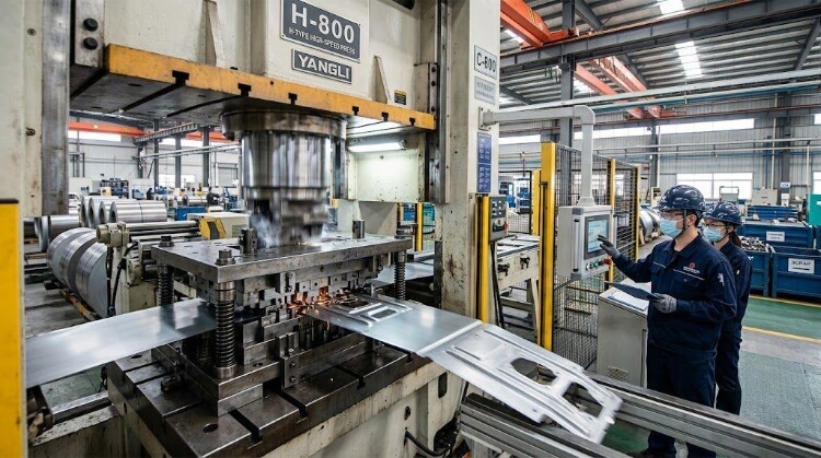
Cold stamping is a metal forming process that shapes sheet metal at room temperature without changing its microstructure. It is widely used in high-volume manufacturing because it supports fast cycle times and consistent part production with stable dimensional control. Compared to hot stamping, cold stamping generally provides better surface finish and higher dimensional accuracy, but it is more sensitive to material selection, part geometry, and tool design.
In real production, many issues do not come from the process itself but from early design decisions. This guide explains material limits, design rules, and common failure cases in a clear engineering-focused way.
How Cold Stamping Deforms Metal?
At its core, cold stamping forces a flat sheet of metal past its yield point (where it permanently deforms) but keeps it strictly below its ultimate tensile strength (where it fractures). Understanding how the metal moves, stretches, and reacts under thousands of tons of pressure is critical to predicting part behavior on the shop floor.
Blanking and forming
Blanking is a shearing process that punches the initial 2D flat pattern out of the raw coil. A proper blanked edge isn’t a single clean cut; it consists of a rollover zone, a burnished (sheared) band, and a fracture zone.
If the clearance between the punch and the die is mathematically incorrect for the specific material thickness, the fracture zone expands. This creates excessive burrs that mandate expensive secondary deburring operations. Forming, by contrast, bends and shapes the blank without cutting, relying entirely on the metal’s inherent ductility to stretch around the punch.
Material flow
Metal does not simply fold into shape; it flows into the die cavity. Controlling this physical flow is the most complex variable in tooling design. If the metal flows too freely, it folds over itself and causes wrinkling. If it is restricted too much, the metal thins out past its mechanical limit and tears.
To prevent this, the tooling must act as a precise control valve. Engineers use friction, specifically placed draw beads, and calculated lubrication to manage exactly how much material is pulled into the punch zone during each stroke.
Stretching and compression
Almost every stamped part undergoes simultaneous stretching and compression. In a standard cup draw, the material pulled over the punch head is heavily stretched (subject to tensile stress), while the outer flange is squeezed together as it is forced into a smaller diameter (subject to compressive stress).
If the compressive forces exceed the material’s structural limits, the flange will buckle. Designing the part geometry and die stages to balance these opposing forces is exactly what prevents catastrophic part failure mid-run.
Springback behavior
When the press opens at the top of the stroke and pressure is released, the metal undergoes elastic recovery. The internal stresses attempt to return the material to its original flat state, causing the bend angle to open up.
This is known as springback. It cannot be eliminated, only managed. Tooling engineers must calculate the exact recovery rate for a specific alloy and thickness, then design the die to “overbend” the part. If the print calls for a 90-degree angle, the die might push the metal to 87 degrees, trusting the elastic recovery to bring it perfectly to 90.
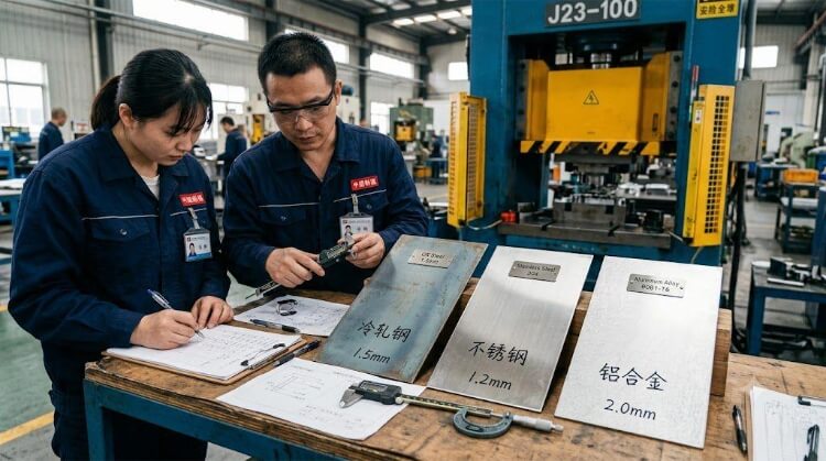
Material Selection in Cold Stamping
Selecting the right metal is a balancing act between the mechanical requirements of the final product and its manufacturability inside the press. Different alloys yield entirely different forming results, dictate the grade of tooling steel required, and heavily influence die maintenance schedules.
| Material Grade | Formability | Springback Risk | Tool Wear Impact | Common Shop-Floor Challenge |
| Low-Carbon Steel (e.g., Q235, 1018) | Excellent | Low | Low | Rust prevention during storage |
| Aluminum (e.g., 5052, 6061) | Moderate | Low | Medium | Galling and surface scratching |
| Stainless Steel (e.g., 304, 316) | Good | Medium | High | Severe work hardening |
| High-Strength Steel (UHSS/AHSS) | Poor | Very High | Very High | Unpredictable dimensional drift |
Low-carbon steel forming
Low-carbon steels are the baseline workhorse for cold stamping. They offer a massive forming window, excellent elongation, and highly predictable material flow.
Because the yield strength is relatively low, springback is easily controlled and tool wear is kept to a minimum. It remains the most cost-effective option for complex, deep-drawn geometries where structural rigidity is required but extreme tensile strength is not.
Stainless steel hardening
Austenitic stainless steels like 304 and 316 have high ductility, making them structurally great for drawing, but they come with a severe manufacturing penalty: rapid strain hardening. As the press deforms the stainless steel, the material’s crystalline structure physically hardens at the bend radiuses.
If a progressive die hits a hardened zone in a subsequent station, the tooling will chip or wear out exponentially faster. Processing stainless requires slower ram speeds, drastically heavier press tonnage, and extreme-pressure (EP) boundary lubricants to prevent the die from overheating.
Aluminum cracking
Aluminum alloys are highly sensitive to bend radiuses and material grain direction. While a 5052-H32 aluminum handles moderate forming well, trying to cold stamp a rigid structural grade like 6061-T6 often results in immediate fracture along the bend line if the radius is too tight.
Furthermore, aluminum has a high tendency to cold-weld or “gall” onto bare steel tooling. When microscopic aluminum particles stick to the punch, it destroys the surface finish of all subsequent parts, forcing the production line to halt for manual die polishing.
High-strength steel springback
Advanced High-Strength Steels (AHSS) and Ultra-High-Strength Steels (UHSS) are increasingly used to reduce part weight without sacrificing structural integrity, but they are notoriously hostile to cold stamping dies.
The immense yield strength of these materials fights the punch at every stage, and springback can vary wildly between coil batches. Stamping UHSS requires aggressive overbending geometries, solid carbide inserts, premium physical vapor deposition (PVD) coatings, and strict tonnage monitoring to maintain batch consistency.
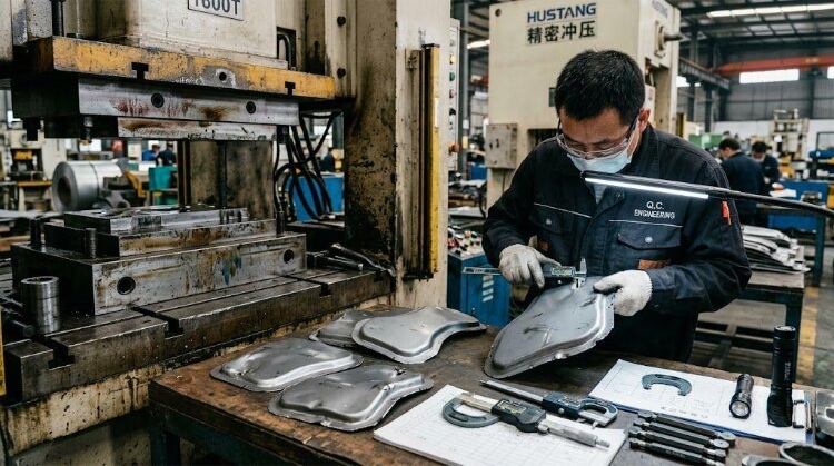
Production Defects and Process Instability
Quality fluctuations occur because cold stamping is a dynamic process. Heat builds up in the tooling, lubricants break down, punches dull, and raw material properties shift. Managing these variables on the shop floor separates a stable production run from a costly disaster.
Wrinkling
Wrinkling happens when compressive forces push the metal together faster than it can be drawn into the die cavity. The excess material has nowhere to go, so it folds over itself, usually along the flanges or walls of a deep-drawn part.
The immediate shop-floor fix involves adjusting the blank holder force. By increasing the pressure on the perimeter of the blank, engineers can restrict material flow and stretch the metal out. If pressure adjustments aren’t enough, draw beads must be machined into the die to act as speed bumps for the metal.
Cost Impact: Scrapped parts and wasted material. Severe wrinkling can also cause the folded metal to jam in the die, leading to catastrophic tool breakage and days of unplanned downtime.
Edge cracking
Edge cracking occurs when the sheet metal is stretched beyond its ultimate tensile limit. It is especially common when forming high-strength steels or flanging outward.
Often, the root cause isn’t just the bending geometry, but the quality of the initial blanked edge. A rough shear edge with micro-fractures acts as a stress concentrator. When that edge is stretched in a subsequent forming station, those micro-fractures tear wide open. Polishing the cutting punches and correcting die clearances will frequently resolve downstream cracking issues.
Cost Impact: High scrap rates during assembly. Micro-cracks that pass visual inspection can fail later under mechanical stress in the final product, leading to expensive field recalls.
Surface galling
Galling is a form of micro-welding caused by extreme friction. As the sheet metal drags across the tooling under massive pressure, microscopic particles of the blank tear off and permanently fuse to the bare steel die.
This is highly problematic when stamping aluminum or stainless steel. Once galling starts, the tooling acts like sandpaper, destroying the surface finish of every subsequent part. Solving this requires upgrading to extreme-pressure (EP) lubricants or applying premium PVD coatings to reduce surface friction.
Cost Impact: Manual die polishing forces the press to stop mid-run. This constant downtime can easily inflate the cost-per-part by up to 30% on that specific batch.
Dimensional drift
Progressive dies are built from hardened tool steel, but they are not immune to wear. After millions of repetitive impacts, cutting edges lose their sharpness and forming radiuses begin to flatten out.
This wear happens gradually, leading to dimensional drift. A critical hole location might shift by 0.05 mm, or a bend angle might open up by half a degree. Catching this requires rigorous Statistical Process Control (SPC) and scheduled maintenance.
Cost Impact: Parts out of tolerance will fail to mate properly in robotic welding or final assembly lines. Waiting for parts to fail quality assurance before pulling a die for sharpening is a guaranteed way to lose money.
Batch consistency
This is the most critical, yet overlooked, variable in mass production. Raw material is not identical from batch to batch. Steel mills operate within acceptable tolerance ranges for yield strength, tensile strength, and material thickness.
A master coil of steel purchased in January might have a yield strength perfectly in the middle of the spec, while a coil delivered in June sits at the absolute high end. The tooling will react differently to both. Experienced engineering teams anticipate these micro-variations and build enough adjustability into the press parameters to maintain stability.
Cost Impact: Unpredictable springback. A new coil batch can suddenly push all parts out of angular tolerance, requiring hours of trial-and-error press adjustments before production can safely resume.
DFM Rules That Reduce Manufacturing Risk
The most expensive time to fix a manufacturing defect is after the tooling is already cut. Design for Manufacturability (DFM) is about aligning the product geometry with the physical limits of the cold stamping process.
Hole diameter limits
Punching small holes in thick metal is a recipe for broken tooling. During the upward stroke, the metal grips the punch tightly. If the punch is too thin, the stripping force will snap it completely off.
The Golden Rule for Hole Diameters:
- Standard Steel/Aluminum: Hole Diameter ≥ 1.0 × Sheet Thickness
- Stainless/High-Strength Steel: Hole Diameter ≥ 1.2 × Sheet Thickness
Ignoring this rule means you will be paying for replacement punches and press downtime throughout the entire lifecycle of the product.
Bend radius control
Designing parts with perfectly sharp inside corners forces the metal to stretch aggressively over a sharp tool edge, almost guaranteeing a fracture along the bend line. Always specify an inside bend radius to distribute the stress.
The Golden Rule for Bend Radiuses:
- Ductile Metals (Low-carbon steel, soft aluminum): Inside Radius ≥ 1.0 × Sheet Thickness
- Rigid Metals (High-strength steel, 6061-T6): Inside Radius ≥ 2.0–3.0 × Sheet Thickness
Punch clearance
The gap between the cutting punch and the die block dictates the quality of the sheared edge. If the clearance is too tight, the metal undergoes secondary shearing, leaving a jagged edge and causing rapid tooling wear. If the clearance is too loose, the metal rolls over heavily before shearing, leaving massive burrs.
The Golden Rule for Clearances:
- Optimal Die Clearance: Typically 5% to 10% of the material thickness, depending on the alloy’s specific shear strength. Precision matters—a mismatch here guarantees expensive secondary deburring operations.
Material grain direction
Sheet metal rolled at the mill has a distinct grain direction, much like wood. The orientation of this grain heavily impacts how the metal behaves when bent.
The Golden Rule for Grain Direction:
- Bend Perpendicular to the Grain: Produces a strong, crack-resistant radius.
- Bend Parallel to the Grain: Separates the material fibers, drastically increasing the risk of cracking.
Designers should avoid locking the part into a restrictive blanking layout on the drawing. Giving manufacturing engineers the freedom to nest the part at the correct angle relative to the coil grain is crucial for production stability.
From Prototype to Mass Production
Scaling a part from a concept to a million-unit production run is where most projects fail. The transition from low-volume fabrication to high-speed progressive stamping is not just a change in equipment; it is a fundamental shift in manufacturing logic.
Prototype validation
Never jump straight into hard tooling. In the validation phase, parts should be manufactured using tooling-free processes like laser cutting, CNC machining, and press brakes. This allows engineering teams to verify the flat pattern, test bend deductions, and confirm assembly tolerances.
The real advantage comes from partnering with a manufacturer who handles both rapid prototyping and final mass production. If a design flaw is found during the CNC stage, changing a laser path takes five minutes. But if your prototyping shop doesn’t understand progressive die constraints, they might validate a design that is physically impossible to stamp later. Validating for mass production must start on day one.
Progressive die tooling
Once the geometry is locked and volume demands increase, the process shifts to a progressive die. Instead of a single hit, the raw coil moves through a series of sequential stations inside a single die block—punching, coining, bending, and finally cutting off the finished part in one continuous press stroke.
The Manufacturing Advantage: A well-designed progressive die can produce hundreds of parts per minute. It removes human handling between operations, eliminating manual loading errors and ensuring strict part-to-part repeatability.
Break-even volume
Progressive dies require a massive upfront capital investment, often ranging from tens to hundreds of thousands of dollars. The decision to switch to cold stamping always comes down to the break-even point.
The Break-Even Logic: If a CNC-machined or laser-cut bracket costs $5.00 to make, and the stamped version costs $0.50, you are saving $4.50 per part. If the die costs $45,000, your break-even volume is 10,000 units.
For any volume above that threshold, cold stamping becomes the most profitable manufacturing method.
Tool wear and maintenance
A progressive die is not a “set and forget” asset. Stamping a million parts means a million high-tonnage impacts. Punches will dull, springs will fatigue, and alignment pins will wear.
Stable mass production relies on preventative maintenance. Experienced manufacturing partners track tool strikes and pull the die for sharpening and shim adjustments before parts fall out of tolerance. Running a die until it produces bad parts is a reactive strategy that destroys profitability.
Cold Stamping Process Limitations
Knowing when not to use cold stamping is just as important as knowing how to optimize it. While it is the undisputed king of high-volume metal forming, cold stamping has rigid physical boundaries. When a design crosses these boundaries, manufacturing costs skyrocket.
Complex geometries
Cold stamping is fundamentally a 2D-to-3D forming process based on a uniform sheet thickness. It cannot create variable wall thicknesses, undercut features, or complex internal geometries (like blind tapped holes or internal webs).
If a part requires mass to be aggressively redistributed or requires varying cross-sections, it belongs in a CNC mill, a die-casting mold, or a forging press.
Deep draw limits
Drawing metal into a deep cylinder or box places extreme stress on the material. The limitation here is known as the Limiting Drawing Ratio (LDR).
The Golden Rule for Drawing:
For a standard single-stage draw, the depth of the drawn part generally should not exceed the diameter of the punch.
Trying to force a deeper draw in a single hit will cause the bottom of the cup to tear out. Deeper geometries require multiple draw stations and intermediate annealing (heat treatment), which drastically increases tooling complexity and cost.
Tight radius forming
You cannot stamp a perfectly sharp, zero-degree inside corner. Metal needs a radius to flow around.
Attempting to force metal into a sharp 90-degree die cavity will either shear the metal completely or require a secondary “coining” operation. Coining requires massive press tonnage to literally crush the metal into the corner, which rapidly destroys tooling and requires oversized press equipment.
Hot stamping transition
As the automotive and aerospace industries push for lighter, stronger components, they increasingly rely on Ultra-High-Strength Steels (UHSS). However, when tensile strengths exceed 1,000 MPa, cold stamping becomes a liability.
The required press tonnage becomes unmanageable, springback becomes entirely unpredictable, and tool steel simply shatters. At this threshold, the process must transition to hot stamping (press hardening), where the steel is heated in a furnace until it becomes malleable, formed in a chilled die, and simultaneously quenched.
Conclusion
Cold stamping remains the most efficient, cost-effective method for mass-producing metal components, but its unit economics are entirely dependent on early-stage engineering. Most cost overruns, quality variations, and missed deadlines are not press failures—they are design failures. By respecting material limits, calculating precise die clearances, and strictly adhering to DFM rules, you can eliminate manufacturing risks before the raw coil is ever loaded onto the feeder.
Is your sheet metal design actually ready for mass production? Send your CAD files to an engineering team with over a decade of hands-on sheet metal fabrication experience. We will run a ruthless DFM review to identify tight radiuses, incorrect hole ratios, and springback risks—ensuring your project transitions seamlessly from a rapid prototype to a flawless mass production run.