Aluminum is widely considered an “easy” metal on the shop floor. It machines faster than steel and is generally forgiving of equipment.
But anyone who has run actual production knows the reality. Clean, dimensionally accurate cutting is never automatic.
In real-world fabrication, what starts as a simple cut can quickly turn into a quality control nightmare. Burrs, thermal expansion, surface tearing, and part movement can ruin a batch before it even reaches the finishing stage.
This guide focuses on the practical side of aluminum cutting: why the material behaves this way, and how to choose the right process for your part geometry, tolerance, and production volume.
Why Aluminum Cutting Can Still Cause Problems?
“Cutting” aluminum is easy; “cutting it well” is a completely different engineering challenge. Because the material is relatively soft, it reacts poorly to incorrect tooling and heat.
Here is exactly why a simple cut often goes wrong.
Soft Material and Edge Quality
Carbon steel shears or fractures cleanly under a cutter. Aluminum doesn’t fracture; it gums up. If your tool isn’t razor-sharp, you are plowing through the metal rather than cutting it.
This dragging action creates heavy, rolled burrs, surface tearing, and severe edge distortion.
If you are cutting panels or rails for a custom server chassis, those torn edges aren’t just ugly. They will cause immediate mating issues during assembly and lead to automatic cosmetic rejections.
Heat, Burrs, and Part Movement
Most aluminum cutting failures come down to a few core variables: excess heat, poor chip evacuation, and vibration.
Aluminum is an excellent thermal conductor. As it heats up from tool friction, the chips expand and pack into the cut. This creates a vicious cycle of heat that rapidly degrades the blade and the edge finish.
Furthermore, thin parts and long extrusions lack rigidity. If they aren’t clamped perfectly, the cutting force induces vibration. This part movement causes chatter marks, angled cuts, and makes holding a tight ±0.005″ tolerance impossible.
How to Choose the Right Cutting Method?
The part’s engineering requirements dictate the best cutting method, not just the machines sitting in your shop.
A process that effortlessly knocks out one aluminum bracket might create massive downstream bottlenecks and extra costs on another.
Thickness and Section Size
Material thickness is the first absolute filter for process selection. For thin sheet metal under 1/4″, laser cutting or precision shearing is the undisputed king.
However, as the plate gets thicker, the rules change entirely.
If you try to laser-cut a 1/2″ or 1″ thick aluminum plate, you will fight severe edge tapering and heat-affected zones (HAZ). Thick plates demand much higher machine rigidity and often require a waterjet or heavy CNC milling to maintain a straight, temperature-controlled edge.
Part Shape and Cut Path
A straight line is cheap, but a complex curve requires the right equipment. The geometry of your part directly dictates your options.
If you are cutting raw stock to length, a standard cold saw or band saw is your most efficient option for simple blanking.
But when the part requires internal cutouts, tight radii, slots, or local trimming, saws are useless. Complex profiles and intricate paths demand a fiber laser, waterjet, or CNC router.
Volume and Repeatability
The method used to make your first 5 prototypes is rarely the method used for your 5,000-piece production run.
During the prototyping stage, flexibility is key. A waterjet offers perfect cold-cut edges and requires zero custom tooling, making it ideal for proving out a design.
But as volume scales, machine hourly rates dictate your margins. That waterjet is too slow and expensive for mass manufacturing. By slightly redesigning the part to be stamped on a high-speed punch press, you can reduce your per-unit cost by 80% while guaranteeing batch-to-batch consistency.
Main Cutting Methods for Aluminum Parts
Each cut-aluminum method has its own place on the shop floor, depending entirely on part geometry, edge-quality requirements, and your cost targets.
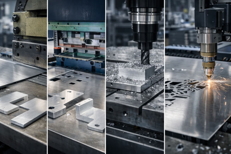
Here is how we evaluate the four main cutting technologies in real-world production:
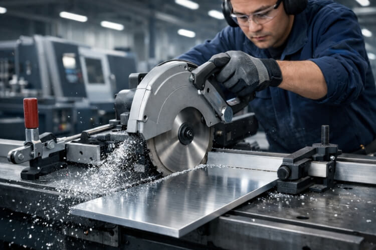
Saw Cutting (Cold Saws and Band Saws)
- Best For: Straight cuts, extrusions, raw stock blanking.
- Watch Out For: surface scratching and heavy burrs if the blade geometry is wrong.
Circular cold saws and band saws are the workhorses of the metal shop. If you need to chop down long extrusions or cut raw bar stock to length, a saw is your most cost-effective tool.
However, saws are strictly 1D and 2D tools. They also require heavy mechanical clamping. If the feed is forced or you aren’t using an aluminum-specific blade, a saw will leave heavy burrs, requiring a costly secondary deburring operation.
Laser Cutting (Fiber Lasers)
- Best For: Thin sheet metal (under 1/4″), complex 2D profiles, high-speed prototyping.
- Watch Out For: Thermal distortion, edge tapering on thick plates.
Fiber lasers have completely revolutionized thin-gauge aluminum cutting. They offer incredible speed for complex internal cutouts and enable rapid prototyping without custom tooling.
But aluminum’s high reflectivity and thermal conductivity create hard limits. Push a laser past its ideal thickness, and you get severe edge tapering and a brittle Heat-Affected Zone (HAZ). For structural components, the HAZ can significantly reduce the metal’s yield strength.
Waterjet Cutting
- Best For: Thick plates (1/2″ to 6″+), tight nesting, zero thermal distortion.
- Watch Out For: High hourly run rates, slower cutting speeds.
When you need to cut a 2″ thick aluminum plate without altering its metallurgical properties, waterjet is the undisputed answer. It is a completely cold-cutting process, meaning zero HAZ, zero heat warping, and a clean, frosted edge.
The trade-off is the commercial reality. Waterjets have high hourly machine rates and cut much more slowly than lasers. Using a waterjet for simple, thin-gauge, high-volume production will destroy your profit margins.
CNC Machining (Milling and Routing)
- Best For: Tight tolerances (±0.001″), critical mating surfaces, complex 3D features.
- Watch Out For: Burning through your budget on simple blanking jobs.
When edge quality and dimensional accuracy are absolutely non-negotiable, CNC machining is the only option. It is the only reliable way to achieve stepped edges, blind pockets, and mirror-finish mating surfaces on an aluminum part.
But use it wisely. Machining is a material-removal process, making it slower and more expensive. Putting a part on a 5-axis mill just to cut an outer profile is a fast way to burn through your project budget.
What Has the Biggest Impact on Cut Quality?
In both rapid prototyping and mass manufacturing, poor cut quality rarely comes from choosing the wrong cutting method. It almost always comes down to setup details.
Here are the four process variables that will actually make or break your cuts.
Blade and Tool Condition: Specific Geometry is Required
Because aluminum is relatively soft, you don’t just need a sharp edge; you need the right geometry. A standard steel-cutting blade will fail immediately on aluminum.
The Tooling Secret: For saw cutting, you must use a Triple Chip Grind (TCG) carbide blade. For CNC routing, single-flute or O-flute end mills are mandatory. These geometries are specifically designed with high rake angles and deep gullets to evacuate soft aluminum chips aggressively. If the chips can’t escape, your tool will pack up, and the edge finish is ruined instantly.
Speed and Feed Control: Finding the Chip Load Sweet Spot
Spindle speed (RPM) and feed rate cannot be guessed. If you feed the material too slowly, the tool rubs against the aluminum rather than cutting it, causing work hardening and excessive friction.
If you feed it too fast, you risk tearing the material, causing a rough, fractured finish, or snapping the cutter entirely.
The Real Killer: The most common cause of a poor surface finish is an unstable feed. Inconsistent feed rates cause variations in chip load. Visually, this translates directly to chatter marks, stepping, and a rough cut along the machined edge.
Lubrication and Chip Removal: The War on “Galling”
Aluminum has a nasty habit of sticking to cutting tools—a physical process known as galling or built-up edge (BUE). When aluminum gets hot, the chips literally weld themselves to the cutting edge.
Once a tool gets loaded with aluminum, it ruins the kerf, damages the part surface, and eventually breaks the tool.
Modern Coolant: In proper fabrication, we don’t just flood the part with water. Advanced shops use MQL (Minimum Quantity Lubrication) or high-pressure mist systems. This provides the exact lubricity needed to stop aluminum from sticking, while utilizing air pressure to blast chips out of the cutting zone before they can be recut.
Clamping and Part Support: Defeating Chatter Without Marring
“The machine is cutting out of tolerance.” We hear this from engineers often, but usually, the machine is perfectly accurate—the fixturing is weak.
Aluminum—especially thin panels or long extrusions—loves to vibrate. If a part isn’t rigidly supported near the cut line, cutting forces can induce harmonics and chatter, leading to severe dimensional inaccuracies.
The Catch: You have to clamp it tightly, but aluminum is soft. Over-tighten standard steel clamps, and you will crush the extrusion or leave deep bite marks. Using custom soft jaws or vacuum fixturing is the only way to hold to tight tolerances without damaging the part’s cosmetic surface.
Common Problems in Aluminum Cutting
Most aluminum cutting failures on the shop floor are not mysteries. They appear in a few predictable, recurring patterns.
If you understand what causes these specific defects, it becomes much easier to trace the root cause, adjust the setup, and save the rest of the production batch.
Burrs and Rough Edges
A heavy burr isn’t just an aesthetic annoyance; it is a hidden manufacturing cost. Burrs usually indicate a dull tool, an incorrect feed rate, or inadequate chip evacuation, which causes the metal to tear rather than shear.
The Cost of Secondary Ops: If every part coming off the saw requires 5 minutes at a manual deburring station, your labor costs just destroyed your profit margin. Furthermore, for structural parts, heavy burrs prevent surfaces from sitting flush during final assembly.
Surface Marks and Tearing
Because aluminum is soft, it is incredibly easy to scratch, gouge, or tear during the cutting process. This happens when chips are dragged across the material face or when fixturing leaves imprint marks.
The Finishing Nightmare: This is a fatal flaw for cosmetic exterior parts. If an aluminum panel is scheduled for clear anodizing, powder coating, or a brushed finish, those surface tears will show straight through. You cannot paint over bad machining.
Blade Loading and Excess Heat
We mentioned “galling” earlier, but here is how it presents on the floor: a sudden spike in spindle load, a smoking cut, and an atrocious, smeared edge finish.
Once aluminum melts onto the teeth, the tool’s cutting geometry is completely ruined.
Alloys Matter: Alloy selection plays a massive role here. Soft, gummy alloys like 5052-H32 are notorious for building up on tools if not heavily lubricated. In contrast, harder alloys like 6061-T6 cut cleaner, but are more prone to chipping if your feed rate is unstable.
Poor Accuracy and Part Movement
When a dimension is suddenly off by 0.010″, the machine itself is rarely broken. The part moved.
Thin sheets and long extrusions are highly susceptible to vibration. If the clamping pressure isn’t evenly distributed, the cutting force can cause the material to flex, shift, or chatter.
The Wandering Cut: Even a millimeter of flex during the cut can cause the tool to deflect. This leads to angled cuts, out-of-spec dimensions, and parts that won’t fit into the welding fixture later.
When Should Cutting Be Replaced by Another Process?
Cutting is a fundamental operation, but it is not always the most efficient or reliable choice. Sometimes, the best way to fix a cutting problem is to change the manufacturing process entirely.
Shearing for Simple Straight Cuts
If you need thousands of simple rectangular blanks from thin sheet metal, putting them on a laser or a CNC saw is a massive waste of machine time.
Speed and Efficiency: An industrial shear acts like a giant pair of scissors. It drops the cycle time from minutes to literal seconds. For simple straight lines and high-volume blanking, shearing offers unmatched cost efficiency, provided complex edge routing isn’t required later.
Punching for Repeated Features
Lasering 50 identical ventilation holes in a server chassis panel takes significant machine time. A laser might take 2 to 3 seconds to pierce and cut every single hole.
Mass Production Consistency: A CNC turret punch press changes the math entirely. It can hit 300-500 per minute. For standard holes, louvers, and slots in volume production, punching guarantees absolute consistency across thousands of parts, eliminates heat-affected zones, and drastically slashes the per-unit cost.
Machining for Tighter Tolerances
Standard cutting methods (such as sawing or waterjet cutting) are essentially “blanking” operations—they separate the metal. They are not designed for high-precision final finishing.
Hitting the Specs: If an engineering drawing calls for a tight ±0.001″ positional tolerance, critical stepped edges, or a perfectly flat mating surface for a heatsink, you must move the part to a CNC mill. Trying to hold precision assembly tolerances on a standard saw is a fool’s errand.
Laser or Waterjet for Complex Profiles
Conversely, you should never use a mechanical saw or router to force through intricate, organic shapes or to nest multiple part variants on a single sheet.
Avoiding Rework: For complex internal cutouts, tight radii, or heavily contoured profiles, mechanical cutting leads to endless setups and manual rework. Transitioning these complex profiles to a fiber laser or waterjet eliminates the need for custom fixturing and enables effortless handling of complex paths.
Conclusion
Cutting aluminum is not just about getting through the material. It is about getting a clean edge, stable dimensions, and a result that fits the next step in your process.
If the method matches the part and the setup is well controlled, most common problems can be avoided early. If the wrong method is used, you will often pay later in the form of increased deburring time, rework, or assembly issues.
If you are working on an aluminum part and are not sure which cutting method fits best, we can help review it before production.
You can send us your drawing or a simple part sketch. We will assess thickness, shape, and quantity, and suggest a practical cutting approach that maintains stable edge quality and avoids unnecessary rework. Upload your drawing or contact us to get a quick review and quote.