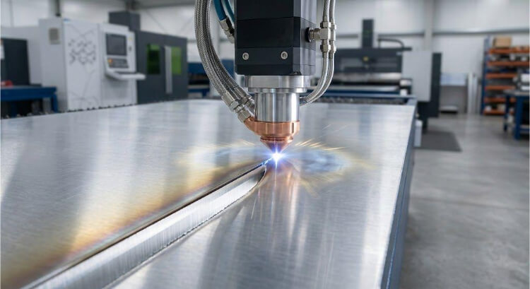
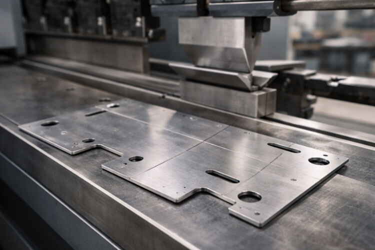
Press brake forming is one of the most common methods for turning a flat sheet into usable parts. It is widely used for brackets, panels, covers, trays, and enclosures because it can create repeatable bends without the tooling cost of stamping.
The process looks simple, but stable results are not automatic. A part may bend once and still be a poor production part. Short flanges, tight radii, nearby features, material variation, and springback can all make a simple drawing difficult.
That is why the real question is not only whether a part can be bent. The real question is whether it can be bent cleanly, held consistently, and repeated across production without constant correction. Good press brake results usually start in the design, long before the first bend is made.
What Is Press Brake Forming?
Press brake forming is a process that bends sheet metal between a punch and a die. The punch moves down, the sheet is pressed into the die opening, and the metal takes on a new angle or profile.
The bend stays because the material is pushed past its elastic limit. After the load is removed, the part springs back slightly but does not return to its flat state. That springback is normal. It is also one of the reasons a bend that looks correct during the hit may still come off angle after unloading.
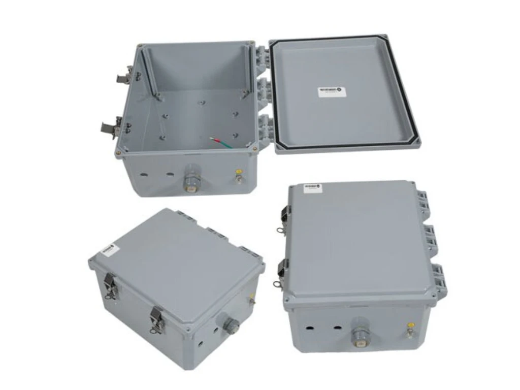
In production, this process is used for flat blanks that become formed parts with straight bends. Common examples include mounting brackets, cabinet parts, electrical covers, support rails, and bent sections used later in welded assemblies. These parts are often simple in shape, but the bend still controls fit, appearance, and downstream assembly.
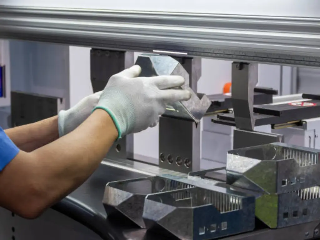
How Press Brake Forming Works?
Not all bends are made the same way on a press brake. The bend method affects angle control, springback, and the job’s stability in production.
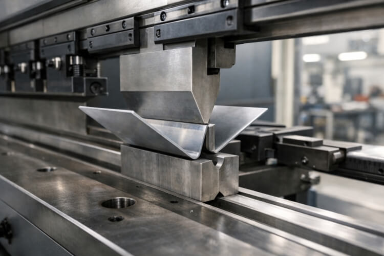
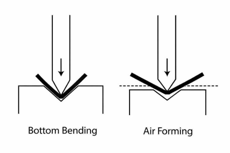
Air bending
Air bending is the most common method in press brake work. The punch pushes the sheet into the die opening, but the material does not fully bottom out in the die.
This method is widely used because it gives good flexibility. The same tooling can often produce different bend angles by changing punch depth. That makes air bending a practical choice for custom parts, prototype work, and jobs with mixed bend angles.
The trade-off is control sensitivity. Because the bend is not fully forced into the die, the final angle is more influenced by thickness variation, material strength, and springback. A setup may run well on one batch and still need correction on the next if the material changes enough to move the angle.
Bottoming
Bottoming pushes the sheet deeper into the die, allowing the material to make fuller contact with the tooling. Compared with air bending, the die has more direct control over the final angle.
That added contact can improve angle stability, especially on parts that need tighter bend control. But it also makes the setup less forgiving. Tool angle, die selection, and material response need to match more closely, and the required force is usually higher than in air bending.
In real production, bottoming can improve repeatability, but it does not rescue weak bend geometry. If the flange is too short or the feature spacing is too tight, the part can still be difficult to run well.
Coining
Coining uses much higher pressure than air bending or bottoming. The punch presses the material hard into the die area, greatly reducing springback and providing a more defined bend shape.
This method can improve angle accuracy, but the cost is higher force, higher tooling load, and lower process flexibility. For many general sheet metal parts, that trade-off is not worth it.
That is why coining is less common in normal custom fabrication. It is usually chosen only when the bend requirement is strict enough to justify the extra force and tighter process window.
Design Rules for Better Bending
Many bending problems start in the drawing, not at the machine. A few design decisions often decide whether the part runs smoothly or becomes difficult to control.
Minimum flange length
Flange length directly affects bend stability. If the flange is too short, the part becomes harder to support during forming, and angle control tends to worsen.
This is one of the most common design problems in press brake work. A flange may still be bendable, but that does not mean it is easy to bend well. Short edges are more likely to shift, deform, or come off the brake, leading to poor repeatability.
As a practical starting point, minimum flange length usually depends on die opening, material thickness, and bend radius. If the flange is too small for the selected tooling, the shop may need special tools or a different bend approach. That adds to the setup difficulty without addressing the real design weakness.
Hole-to-bend distance
Features placed too close to the bend line often create trouble. A nearby hole, slot, or cutout can stretch, distort, or shift once the surrounding material starts to form.
This happens because the bend zone does not move alone. Material around the bend also changes shape and stress state during forming. If the feature sits too close, that area stops behaving like stable flat stock and starts behaving like part of the bend.
In many routine jobs, about 2 to 3 times the material thickness is used as a rough, early check of the hole-to-bend distance. The real requirement still depends on feature size, bend radius, material, and tolerance demand. A part may still form with less clearance, but the feature quality usually becomes less reliable.
Inside bend radius
Inside bend radius affects both bend quality and crack risk. If the radius is too small for the material, the outer surface experiences higher strain during forming, increasing the risk of splitting or surface damage.
This matters more in stainless steel, harder aluminum tempers, and thicker sheet. A small radius may look clean on the drawing, but it usually leaves less forming margin on the floor.
In many general designs, an inside radius approximately equal to the material thickness is a practical starting point. The best value still depends on material and temper. A larger radius usually improves formability, but it also changes flat pattern development and final fit. That is why bend radius should be treated as a real process decision, not just a drawing detail.
Bend relief
Bend relief helps reduce stress concentration near edges and corners during bending. Without enough relief, the material near the bend end may tear, bulge, or distort as the bend forms.
This often shows up when a bend stops near an edge, a corner, or another formed feature. The flat pattern may look simple, but the edge condition becomes unstable once the sheet starts to move.
A small bend relief can make the bend cleaner and more repeatable. It is a simple design feature, but it often prevents edge damage that is much harder to fix after the part is already formed.
Grain direction
Grain direction can change how safely a part bends. When the bend line runs across the grain, the material usually cracks less. When the bend runs with the grain, crack risk increases more rapidly, especially in harder materials or tighter-radius bends.
This is not equally critical everywhere, but it becomes more important when the design already has a low forming margin. Aluminum and stainless steel usually make this easier to see.
That is why grain direction should not be treated as a minor detail on tighter bends. A bend may look acceptable in CAD, but become risky in production if the material direction is against the bend.
Common Press Brake Forming Problems
Press brake parts often fail in predictable ways when bend conditions are too aggressive or unstable. The key is to understand what the problem is, why it happens, and where to correct it.
Springback
Springback is the angle loss that appears after the punch comes back up. After the punch is removed, the material tries to recover part of its original shape, so the bend opens slightly.
This happens because part of the material deformation is elastic. Stronger materials usually spring back more. Stainless steel and harder aluminum tempers often show this more clearly, and air bending is usually more sensitive because the final angle depends more on material response.
The right fix is usually process control, not extra force by itself. Better bend compensation, tighter control of punch depth, a different bend method, or a material condition with less springback usually does more than simply pushing harder. If springback is already high, it is usually better to widen the process margin early than keep correcting parts after they are formed.
Bend marks
Bend marks are lines or surface damage left by tooling contact during the bend. On non-cosmetic parts, light marking may be acceptable. On visible covers, doors, or finished panels, the same mark can turn a usable part into rework.
The cause is usually straightforward. The sheet is pressed into the tooling under load, and the contact condition leaves a mark. Small die openings, worn tooling, high contact pressure, and poor part orientation usually make the problem worse. Stainless steel, aluminum, and painted surfaces make it easier to see.
The best fix is to control the contact before the part reaches production. Cleaner tooling, a more suitable die opening, better part orientation, and surface protection usually help more than trying to clean up the result afterward. When appearance matters, cosmetic control has to be treated as part of the bend setup.
Cracking
Cracking occurs when the outer surface of the bend is stretched beyond the material’s limit. It may start as a fine surface split or open enough to reject the part immediately.
The usual cause is a bend condition that is too severe for the material. A small inside radius, a hard temper, or bending with the grain can all reduce bend margin. This usually shows up faster in stainless steel, thicker sheet, and harder aluminum tempers.
The normal fix is to reduce strain at the bend. A larger inside radius, a softer temper, a better grain direction, or a less aggressive bend condition usually helps more than extra tonnage. When cracking appears, the first question should be whether the bend design is too tight for the selected material.
Twisting
Twisting occurs when the part does not remain stable throughout the stroke. One side lifts, rotates, or moves differently, and the bend distorts instead of remaining balanced.
This usually comes from unstable geometry during forming. Narrow parts, asymmetric shapes, and parts with uneven support around the bend line are more likely to twist. A bend sequence can also make the problem worse when earlier bends reduce stability for later ones.
The fix is usually better control, not more force. Better support, better bend order, and better handling usually solve more than pushing harder. If twisting continues, the part may need a geometry change so the bend can be made under more stable conditions.
Inconsistent bend angles
Inconsistent bend angles occur when the setup does not yield the same result across the full run. The first part may be correct, but the latter parts drift enough to create fit or assembly problems.
This usually comes from process variation rather than a single cause. Material thickness changes, yield variation, setup movement, tooling wear, and part positioning can all shift the final angle. Long bends usually make the problem easier to see.
The fix is to control the run, not just the sample. Stable material, repeatable setup, good tooling condition, and clear angle checks matter more than getting one part right at the start. A first article can pass, and the job can still drift later if the process itself is not stable.
When Press Brake Forming Is the Right Choice?
Press brake forming is useful, but it is not the best fit for every part. The right choice depends on geometry, volume, and what the job really needs.
Better than welding for some bent parts
Press brake forming is often the better choice when one bent blank can replace several welded pieces. Fewer pieces usually mean fewer joints, less welding time, and less post-processing.
That improves more than the cost. Less welding usually means less heat distortion, fewer alignment variables, and fewer chances for fit-up trouble later. For brackets, trays, covers, and many enclosure parts, bending one piece is often easier to control than building the same shape from several smaller sections.
Better than machining for many simple shapes
Press brake forming also makes sense when the part’s shape is mainly determined by bends rather than by heavy material removal. If a part starts as a sheet and mainly needs flanges, folded walls, or formed sections, machining the same shape from solid stock is usually the less efficient route.
Machining creates the form by removing material. Bending creates the form by moving material. For many panels, covers, brackets, and support parts, that usually means lower waste and a simpler process flow.
When stamping may be a better option?
Press brake forming is flexible, but it is not always the best answer. Stamping may be the better choice when the part design is stable, the bend features repeat in high volume, and dedicated tooling can be justified.
In that situation, stamping can reduce cycle time and improve throughput. The front-end tooling costs are much higher, but the cost per part may fall quickly once the run is large and stable enough.
When should rolling form be a better option?
Roll forming may be a better fit when the part is long and keeps the same cross-section from one end to the other. That kind of geometry is different from the discrete bend lines normally made on a press brake.
Press brake forming works best when the part has defined bends made one step at a time. Roll forming works better when the profile stays continuous along the full length.
How to Improve Bending Results?
Better bend quality usually comes from earlier decisions, not later corrections. Small changes in design, tooling, and setup often make the biggest difference.
Design with bending limits in mind
Better bending usually starts at the drawing, not at the machine. A part may look acceptable in CAD and still be hard to run if the flange is too short, the inside radius is too small, or features sit too close to the bend line.
The most effective fix is to build more bend margin into the design before production starts. A slightly larger radius, more clearance near the bend, or a better bend direction often improves stability without changing part function. These are small changes to the print, but they usually reduce more risk than a late setup correction.
Match tooling to the part
Tooling has to match the bend requirement, not just the setup that is already on the machine. Punch shape, die opening, and bend method all affect angle control, surface condition, and process stability.
The right approach is to choose tooling based on material, target radius, bend length, and surface requirements. A die opening that is too small may increase force and marking without improving the real result. A die opening that is too large may reduce control on thinner parts or narrow features. In many routine jobs, die width is often selected around 6 to 10 times material thickness, but the final choice still has to fit the part.
Review critical bends before production
Not every bend matters in the same way. Some bends are easy to make and easy to hold. Others control assembly fit, visible appearance, or the position of later operations.
The useful fix is to identify those critical bends before the job runs. If one bend drives part fit or appearance, it should be checked as a key process point, not treated like the rest of the geometry. This usually prevents the common situation in which parts pass basic bending but still cause trouble in assembly or finishing.
Use prototypes to reduce risk
Prototype bends are useful because they show where the drawing is weak. Springback, marking, local distortion, and bend-order problems often appear only after the part is actually formed.
The best use of a prototype is not just to prove the part can be bent once. This is to confirm that the part can be bent stably. That gives the team a chance to adjust radius, clearance, tooling, or bend order before the job moves into repeat production. In most cases, a small correction at the prototype stage is much cheaper than repeated corrections during the run.
Conclusion
Press brake forming remains one of the most practical ways to turn a flat sheet into repeatable parts. It works well for brackets, panels, covers, trays, and enclosures because it gives good forming flexibility without the tooling cost of stamping.
Planning a sheet-metal part that requires press-brake forming? We support projects from prototype to production and can help with bend review, manufacturability feedback, and custom quotations. Send us your drawings or project details so we can discuss the best forming approach for your part.