
Most metal parts do not fail from a single heavy load. They often fail because of fatigue. Small cracks start at the surface, then grow slowly under repeated stress. Shot peening is a controlled surface treatment that helps reduce this risk.
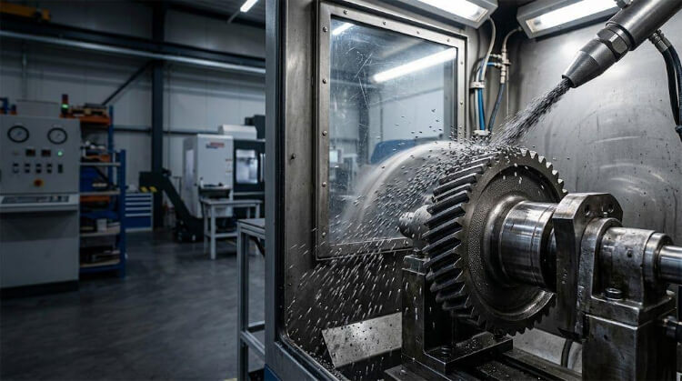
Shot peening is a cold-working process that improves fatigue life by striking the surface with small, round shot. These impacts induce controlled plastic deformation and form a compressive residual-stress layer. This layer helps slow crack growth and makes parts such as gears, springs, and shafts more durable.
This article explains how shot peening improves fatigue resistance, where it is worth using, and what engineers and buyers should confirm before adding it to a production plan.
What Shot Peening Does to Metal Parts?
To understand the value of shot peening, you have to look at what happens at the microscopic level when thousands of spherical media hit a metal surface at high velocity.
Surface Plastic Deformation
When the spherical media (steel shot, glass beads, or ceramic) strikes the metal, it acts like a tiny peen hammer. The impact creates a microscopic indentation or “dimple.”
This stretches the very top layer of the metal, causing it to yield. This permanent change in shape is known as plastic deformation.
Residual Compressive Stress
This is the core mechanic of the process. While the impacts stretch the top layer of the metal, the underlying material remains intact and resists this expansion.
Because the substrate essentially “pulls back” on the deformed surface layer, this tension creates a permanent, highly stressed state on the surface. This is known as residual compressive stress.
Fatigue Crack Resistance
Why does compressive stress matter? Because cracks require tensile stress (pulling force) to open and propagate. The compressive stress layer created by shot peening acts like a heavy clamp, holding the metal’s surface tightly together.
Even if the part is subjected to heavy operational loads, the applied tensile stress must first overcome the built-in compressive layer before a crack can form. Depending on the material and application, shot peening can extend fatigue life by 300% to 1000% compared to unpeened components.
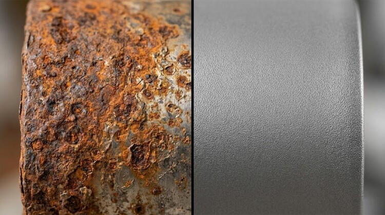
Shot Peening vs. Shot Blasting
These two processes are frequently confused, but they serve entirely different purposes on the factory floor. Here is the strict distinction:
| Item | Shot Peening | Shot Blasting |
|---|---|---|
| Main purpose | Improve fatigue life | Clean or roughen the surface |
| Main effect | Creates compressive surface stress | Removes rust, scale, or coating |
| Media shape | Controlled round media | Abrasive or irregular media may be used |
| Process control | Higher control required | Wider process window |
| Common use | Gears, springs, shafts, aircraft parts | Cleaning, descaling, coating preparation |
| Result on part performance | Can improve fatigue resistance | Usually does not improve fatigue life |
Suitable Applications for Shot Peening
Shot peening adds cost and a step to the manufacturing routing, so it should be applied where it delivers a clear return on investment in part longevity and reliability.
Repeated Loading Parts
Any component subjected to high-frequency cyclic loading is a prime candidate. This includes suspension springs, transmission gears, drive shafts, and torsion bars.
Peening allows these parts to handle millions of stress cycles without failure. This often enables engineers to design them lighter and smaller, reducing overall material weight.
Stress Concentration Areas
Geometries like sharp internal corners, fillets, grooves, and keyways act as stress multipliers. In sheet-metal-formed parts or complex brackets, the bending process itself can introduce residual tensile stress.
Shot peening these specific target zones neutralizes the built-in tension. It effectively fortifies the weakest points of your design.
Machined Parts Under Fatigue Risk
Even high-precision CNC machining leaves behind microscopic tool marks and scratches. Under heavy loads, these tiny imperfections act as the starting points for micro-notches and eventual cracks.
Shot peening effectively neutralizes the mechanical impact of these tool marks. It replaces vulnerable surface tension with a uniform, protective compressive layer.
Safety-Critical Components
In aerospace, automotive, and heavy industrial equipment, part failure is catastrophic. Components like turbine blades, landing gear, and heavy-duty brackets are heavily regulated.
These parts are routinely shot-peened to ensure they meet strict, non-negotiable safety margins. To ensure repeatability, these processes are executed and verified in strict accordance with industrial standards such as SAE AMS 2430 or MIL-S-13165.
Material Factors That Change the Peening Decision
Different alloys respond differently to cold working. The mechanical properties of the base material dictate the choice of peening media, the required intensity, and the specific quality controls needed to prevent contamination or surface damage.
Steel
Standard carbon and alloy steels respond exceptionally well to shot peening. The process reliably pushes their fatigue limits much higher.
For these materials, cast steel shot is the standard media. Because the material is hard and durable, it can withstand high-intensity peening to generate a deep compressive stress layer, ideal for heavy-duty transmission components and industrial machinery.
Stainless Steel
The critical risk with stainless steel is iron contamination. If standard carbon-steel shot is used, microscopic iron particles will embed in the stainless surface, leading to rapid rust and galvanic corrosion.
To maintain the alloy’s anti-corrosive properties, stainless steel parts must strictly be peened using stainless steel shot, glass beads, or ceramic media.
Aluminum
As a significantly softer material, aluminum is highly susceptible to surface damage from over-peening. Using too much kinetic energy can cause surface tearing, fold-overs, or excessive roughness, which actually creates stress risers rather than eliminating them.
For aerospace brackets or high-performance CNC-machined aluminum enclosures, peening is done at much lower intensities, typically utilizing glass beads or fine ceramic media to ensure a smooth, uniform stress layer.
Titanium
Titanium has an excellent strength-to-weight ratio but is prone to notch sensitivity and galling. Any surface imperfection can quickly lead to crack propagation.
Shot peening is critical for titanium aerospace and medical components. The process usually requires hard, exceptionally smooth ceramic media. Strict controls are necessary to ensure the media remains perfectly spherical, as shattered media will immediately compromise the titanium’s surface integrity.
Process Controls That Affect Part Quality
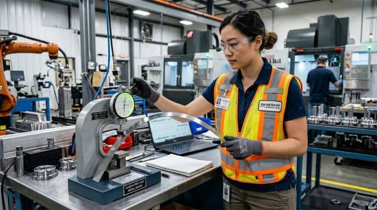
Quality in shot peening cannot be verified by just looking at the finished part. The compressive stress layer is invisible. Therefore, quality assurance relies entirely on rigorous control of the mechanical variables during the process.
Media Type and Condition
The media must remain perfectly spherical. Over time, impacts cause the media to fracture. Broken, angular media acts like abrasive grit—it cuts into the metal instead of dimpling it, creating micro-notches that accelerate fatigue failure.
Industrial peening machines must utilize continuous vibrating screen classifiers and shape-sorting mechanisms to remove fractured particles from the system immediately.
Peening Intensity
Intensity is the measure of kinetic energy transferred to the part. It dictates the depth of the compressive stress layer.
This is not a guessing game. Intensity is mechanically controlled by adjusting air pressure (in pneumatic systems) or wheel RPM (in centrifugal systems), along with the media’s mass and flow rate.
Almen Strip Testing
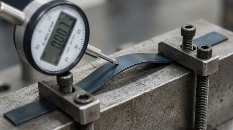
To quantify and verify intensity, engineers use Almen strips in accordance with SAE J442.
An Almen strip is a standardized piece of spring steel. It is clamped to a block and exposed to the peening blast. The induced stress causes the strip to curve. The arc height of this curve is measured on a specialized precision gauge, providing a repeatable, numerical value for the peening intensity (measured on the A, N, or C scale).
Surface Coverage and Inspection
Coverage is the percentage of the part’s surface that the peening media have struck. To ensure no weak points remain, specifications often call for 100%, 150%, or even 200% coverage.
Visual verification of 100% coverage is difficult. For critical components, engineers use fluorescent tracer dyes (per standards such as SAE AMS-S-13165). The part is coated before peening; under a UV light after the process, any remaining glowing dye indicates areas that lack sufficient coverage.
Design and Manufacturing Risks Before Peening
Engineers must design with the peening process in mind. Because peening physically stretches the surface and alters the stress profile, it can distort dimensions or ruin poorly planned parts, particularly in precision machining and general sheet metal fabrication.
Thin Walls and Flat Panels
Peening induces severe stress on the outer layer. If you peel a thin sheet-metal panel or a CNC part with very thin walls, the compressive stress on the surface can overwhelm the core material, causing massive warping, bowing, or buckling.
As a general rule of thumb in precision manufacturing, wall thicknesses below 0.060″ (1.5mm) are at high risk of severe distortion. These require specialized low-intensity peening, masking, or double-sided simultaneous processing to balance the stress.
Tight Tolerance Features
Shot peening displaces metal. As the dimples form, the material “flows” slightly. This means high-precision holes can shrink, and tightly toleranced shaft diameters can grow—typically by 0.0001″ to 0.0005″ (0.0025mm to 0.0127mm) depending on the peening intensity.
If a part features bearing bores with tight H7 tolerances, critical mating surfaces, or fine-threaded holes, these areas must be masked off with specialized tapes or custom urethane plugs before peening begins.
Surface Roughness Limits
By definition, creating thousands of microscopic dimples increases the surface roughness (Ra) of the part. A surface that leaves the CNC mill with a smooth 32 micro-inch (0.8 µm) Ra finish can easily jump to 125 micro-inch (3.2 µm) Ra after standard peening.
If a specific sealing surface or cosmetic finish is required, shot peening will destroy it. Engineers must either mask these zones or plan for a secondary, highly controlled polishing process (like isotropic superfinishing) that smooths the peaks without removing the deep compressive stress layer.
Peen Forming and Distortion Control
Instead of treating distortion as a risk, experienced sheet metal engineers use it as a tool.
By aggressively peening only one side of a flat sheet metal panel, the induced stress forces the metal to curve smoothly. This technique, known as peen forming, is used to manufacture aerodynamic curves or to strategically correct minor distortions caused by previous stamping or welding operations.
Manufacturing Sequence and Post-Processing Rules
Shot peening is practically useless if performed at the wrong stage of the manufacturing process. Because the process relies on a thin surface layer of stress, subsequent manufacturing steps can easily compromise the protective barrier.
After Machining
All heavy material removal—including CNC milling, turning, and drilling—must be completed to 100% before shot peening. The compressive stress layer is exceptionally thin, often ranging from just 0.005″ to 0.030″ (0.12mm to 0.76mm) deep.
If you machine a surface after it has been peened, you will literally cut away the protective layer. This immediately returns the part to its original, fatigue-prone state.
After Heat Treatment
Heat treatment fundamentally alters the metal’s internal microstructure. If a part is shot-peened and then placed into a high-temperature hardening furnace, the thermal energy will cause the metal lattice to relax.
This completely erases the residual compressive stress. Therefore, shot peening must always be performed after all heat-treating and quenching processes are finished.
Before Coating or Plating
Shot peening creates a uniformly dimpled, microscopically textured surface. This makes it an outstanding mechanical anchor for subsequent surface finishes.
It should serve as the final mechanical operation on the factory floor. It is the perfect preparatory step right before the part moves to chemical treatments, anodizing, powder coating, or plating.
Heat and Grinding Limits After Peening
Once a part is peened, it must be handled with care. Aggressive mechanical grinding is strictly prohibited, as it generates intense localized heat and removes material.
Thermal exposure must also be strictly limited. For standard steel components, exposure to operating or baking temperatures above 450°F (230°C) will begin to relax the compressive stresses. For aluminum parts, the threshold is even lower, typically around 200°F (93°C).
Cost, Lead Time, and RFQ Requirements
Transitioning a part from rapid prototyping to mass production requires a clear understanding of how secondary processes impact your bottom line. Here is what buyers need to know when sourcing shot-peened components.
Cost Drivers
The peening process itself is relatively inexpensive. The biggest actual cost multiplier is masking.
If your design requires tight-tolerance bores or delicate threads to be shielded, technicians must manually apply custom masking tapes. While manual taping adds cost during the rapid prototyping phase, transitioning to mass production changes the equation.
For high-volume runs, we utilize custom-molded, reusable urethane plugs. This eliminates manual labor and significantly reduces per-part cost.
Lead Time Impact
For standard components, adding a shot peening operation typically extends the manufacturing lead time by 1 to 2 business days.
In a well-optimized supply chain, this is a negligible delay. It is heavily outweighed by the massive gains in part longevity and drastically reduced warranty claims down the line.
Drawing Callouts
A drawing that simply says “Shot Peen” is a massive red flag in precision manufacturing. It leaves the process open to interpretation, leading to inconsistent outcomes across batches.
Instead of writing a vague note, copy and paste this standard format directly into your engineering drawings:
Shot Peen to 【0.008-0.012 A】 Intensity, 【100%】 Visual Coverage per 【SAE AMS 2430】 standard. Mask all threaded holes.
Supplier Communication
When issuing a Request for Quote (RFQ), clear communication eliminates friction. Highlight any critical sealing surfaces, mating faces, or tapped holes that cannot withstand dimensional changes or increased roughness.
A reliable manufacturing partner will review these geometries during the Design for Manufacturing (DFM) phase. They will propose the safest and most cost-effective masking strategy before production even begins.
Conclusion
Shot peening is not a cosmetic afterthought; it is a highly controlled mechanical upgrade. By deliberately inducing residual compressive stress, engineers can push the physical limits of metal alloys.
It drastically reduces the risk of catastrophic fatigue failure in high-stress applications. From neutralizing CNC tool marks to preventing microcracks in sheet-metal weld zones, it is an indispensable tool in modern manufacturing.
Looking to optimize your next manufacturing project?
At TZR, surface engineering shouldn’t be left to chance. Our team of engineers brings 10 years of experience in precision CNC machining and general sheet metal fabrication to ensure your parts are built to last. Submit your drawings to us today for a free DFM review, and let our experts ensure your custom products are built to last.