
Processing stainless steel requires a fundamental shift in stamping strategy compared to mild steel or aluminum. On the shop floor, engineers battle severe springback, rapid tool wear, and the constant threat of galling.
A single Design for Manufacturability (DFM) oversight early in the design phase can easily double your per-part production costs and reduce tool life by 70%. Success relies on matching your part geometry with robust tooling design and realistic volume expectations.
The following breakdown details the practical engineering constraints of stainless steel sheet metal stamping. We focus on material selection, defect prevention, and cost-control logic—from rapid prototyping through high-speed progressive die production.
Stainless Steel Stamping Creates More Forming Challenges
The same mechanical properties that deliver excellent corrosion resistance make stainless steel notoriously difficult to form. You must engineer specific adjustments at the press to manage the material’s aggressive behavior.
Work Hardening
Austenitic grades (such as the 300 series) exhibit a high work-hardening rate. As the metal deforms during stamping, its microstructural lattice alters, increasing its physical hardness.
Consequently, subsequent forming stations in a progressive die will require exponentially higher tonnage. If drawing speeds or blank holding pressures are miscalculated, the material work-hardens prematurely. This leads to severe cracking and fracturing rather than controlled material flow.
Springback
Stainless steel features a significantly higher yield strength than standard cold-rolled steel, resulting in aggressive springback after forming.
When the press cycles open, the metal attempts to return to its original flat state. Tooling engineers must calculate and design for precise overbending. For instance, holding a strict 90° tolerance often requires machining the punch and die to 93°, forcing the material to relax exactly into the specified dimension.
Galling and Tool Wear
Galling is the most frequent and costly failure mode in stainless stamping. High friction across the die radius strips the material’s passive oxide layer. The exposed bare stainless then cold-welds directly to the tool steel.
Once galling initiates, production stops. You lose valuable time polishing the die every few thousand hits, which delays delivery schedules and spikes tooling maintenance costs. Mitigating this requires specialized extreme-pressure (EP) lubricants or advanced PVD tool coatings.
Forming Force
Due to its high tensile strength and rapid work-hardening, stainless steel demands heavy press tonnage.
A 2mm thick bracket that runs smoothly on a 100-ton press in mild steel will easily require a 200-ton machine for the exact same geometry in stainless. This higher tonnage dictates larger equipment, which directly drives up the hourly machine rates applied to your production quote.
Material Selection Drives Stability and Cost
Specifying the correct alloy and temper is the foundation of cost control and process stability. Over-specifying inflates your raw material budget; under-specifying causes scrap rates to spike during forming.
304 Stainless Steel
304 remains the industry-standard austenitic alloy for stamping. It delivers excellent ductility for general forming, bending, and moderate drawing operations. For the vast majority of industrial, appliance, and structural sheet metal enclosures, 304 strikes the most practical balance between formability, corrosion resistance, and material cost.
316L Stainless Steel
316L contains added molybdenum, drastically improving its resistance to chlorides and chemical attack—but at a significant cost premium.
Specify 316L only for components operating in harsh environments, such as marine hardware or medical devices. Defaulting to 316L for standard indoor or mild outdoor components is a massive waste of budget.
430 Stainless Steel
430 is a nickel-free, ferritic alloy. It is magnetic and generally cheaper than the 300 series, but sacrifices formability and corrosion resistance.
It is viable for cost-sensitive, simple geometries like internal chassis brackets. However, avoid 430 for unpainted, external cosmetic parts, as it remains susceptible to minor surface oxidation and fingerprinting over time.
Deep Drawing Grades
Standard 304 often tears during the deep drawing of housings, cups, or cylindrical parts. For severe stretch-forming, you must specify Deep Drawing Quality (DDQ) or Extra Deep Drawing Quality (EDDQ).
These specialized grades feature a controlled grain structure and lower yield strength. This permits the metal to flow evenly into the die cavity without excessive wall thinning or corner tearing. Often, optimizing the draw beads in tandem with DDQ material is the only way to stabilize a deep-draw production run.
Material Selection Quick Reference:
- 304: The versatile standard. Best for 80% of standard stamping and forming applications.
- 316L: The problem solver. Specify ONLY for severe chemical, marine, or medical environments.
- 430: The budget option. Viable for cost-sensitive, internal, or magnetic requirements in dry environments.
- DDQ/EDDQ: The flow specialists. Mandatory for deep enclosures and complex stretch-forming operations to prevent tearing.
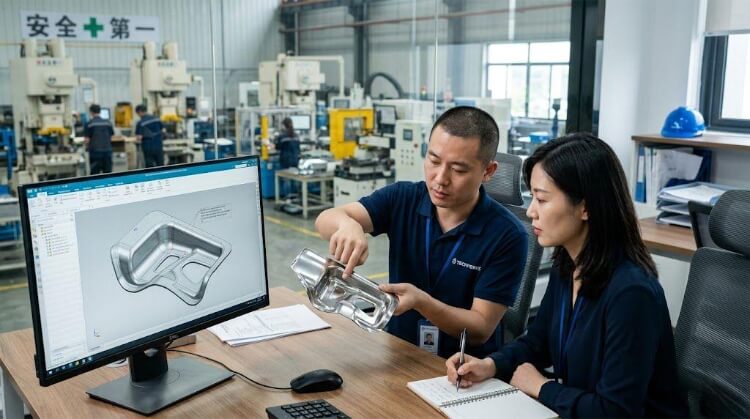
Part Design Features That Lead to Stamping Issues
Part geometry dictates whether a stainless steel component can be stamped efficiently or if it will become a production bottleneck. Complex features that ignore the physical limits of the material force severe compromises on the shop floor, resulting in elevated scrap rates and multiplying tooling investments.
Sharp Corners
Sharp internal corners act as massive stress concentrators during forming operations. Due to the aggressive work-hardening rate of austenitic stainless grades, these high-stress areas are the first to fracture under press tonnage.
Always engineer a generous internal corner radius into the CAD model. We recommend a minimum radius of 0.5 times the material thickness (0.5T) to reduce localized tool wear and prevent edge tearing.
Small Holes
Punching holes in stainless steel requires significant shear force. If a hole diameter is too small relative to the material thickness, the compressive stress on the tooling exceeds its structural limit, and the punch will snap before the stainless sheet shears.
The standard shop-floor rule is that hole diameters must exceed the material thickness. For stainless steel, keeping the minimum diameter at 1.2T or larger prevents catastrophic punch breakage and the associated downtime required to pull the die.
Narrow Flanges
A flange must provide enough surface area for the tooling pad to clamp the material securely during the bending cycle. If a flange is too narrow, the blank will slip under pressure, causing severe dimensional distortion across the entire part.
To guarantee stable forming, specify a minimum flange width of at least four times the material thickness (4T), plus the bend radius.
Deep Draw Ratios
Pushing stainless steel into a deep cavity stretches the material to the extreme edge of its elongation limits. Exceeding the safe draw ratio results in severe wall thinning and eventual rupture at the punch radius.
If your component depth exceeds this limit, the process requires multiple consecutive drawing stations. Every additional station integrated into a progressive die increases the overall tooling investment by several thousand dollars.
DFM Rules for Stainless Steel Stamping Reduce Scrap and Tooling Changes
Applying strict Design for Manufacturability (DFM) rules during the engineering phase prevents expensive tooling modifications later. Adjusting a CAD model costs nothing; pulling and modifying a hardened tool steel die costs thousands of dollars and halts production.
Bend Radius
Tight bends aggressively stretch the outer fibers of the sheet metal. In high-tensile stainless steel, this stretching quickly exceeds the material’s yield strength, leading to micro-cracking along the external bend line.
Specify a minimum bend radius of 1T to 1.5T for standard 300 series alloys. If the application demands harder tempers, the bend radius must be proportionally increased to prevent fracturing.
Hole Placement
Locating holes too close to a bend line guarantees geometric deformation. As the metal stretches to form the radius, it pulls the adjacent hole out of its circular tolerance.
Keep the edge of any punched hole at least 1.5T to 2.5T away from the start of the bend radius. If functional requirements dictate placing the hole closer, it cannot be punched in the flat blank; it must be added as a secondary punching or laser operation after the bend is formed, increasing cycle time.
Grain Direction
Stainless steel sheet possesses a distinct grain structure resulting from the mill’s cold-rolling process. Bending parallel to this grain severely weakens the structural integrity of the part and frequently causes cracking.
A part design might survive initial prototyping on a CNC press brake, but it will fail completely in a high-speed progressive die if the grain direction isn’t aligned within the blank layout. Always orient the flat pattern so that bends occur perpendicular to the material grain.
Relief Cuts
Attempting to fold a flange that sits flush against an unbent edge forces the material to tear at the corner. This uncontrolled tearing damages the part and accelerates wear on the tooling.
Adding bend relief cuts isolates the bending forces and prevents tearing. The width of a relief cut should be at least equal to the material thickness (1T), and its depth must extend slightly past the internal bend radius.
Tolerance Control
Specifying unnecessarily tight tolerances drives up both tooling complexity and quality control costs. While progressive stamping is highly repeatable, expecting CNC-machining levels of precision from stamped sheet metal demonstrates a misunderstanding of the process.
Standard, cost-effective stamping tolerances for stainless steel generally fall between ±0.1mm and ±0.25mm. Holding tighter tolerances usually requires integrating costly secondary shaving operations or precision coining stations into the die.
Common Defects in Stainless Steel Stampings
Even with optimized geometry, shop floor variables will introduce defects. Rapid identification and correction of these issues are critical to maintaining process stability and controlling hourly production costs.
Cracking
Cracking is localized material failure, usually occurring at tight bend radii or during aggressive deep drawing. It is the direct result of exceeding the alloy’s elongation limits or inducing severe work hardening before the form is complete.
Resolution: Increase the bend radius, alter the blank’s grain orientation, or transition the raw material to a Deep Drawing Quality (DDQ) alloy to improve material flow.
Wrinkling
Wrinkling is a compressive failure that typically manifests on the flanges of deep-drawn parts. It occurs when the blank holding pressure is insufficient, allowing the metal to buckle and bunch up rather than flowing smoothly into the die cavity.
Resolution: Adjust the pressure pads to increase holding force or modify the die clearance to better control the material flow dynamic.
Burrs
Burrs are an inevitable byproduct of any shearing or punching operation. However, excessive burr height indicates tooling degradation or improper setup.
Resolution: We control burr height by maintaining strict die clearances—typically between 5% and 8% of the material thickness for stainless steel. This must be coupled with a strict maintenance schedule, pulling and sharpening punches every 50,000 hits before edge degradation occurs.
Surface Scratches
Cosmetic surface damage on the stamping line is generally caused by galling or poor material handling. This is a critical failure for external components like medical enclosures or appliance panels.
Resolution: Prevent galling by applying advanced PVD coatings (like TiCN or AlTiN) to the tool steel and utilizing high-quality, extreme-pressure (EP) stamping lubricants formulated specifically for stainless alloys.
Distortion
Distortion, or warpage, occurs when the severe residual stresses trapped within the stainless steel are released upon exiting the press. The part physically twists out of its dimensional tolerance after forming.
Resolution: Correcting distortion often requires engineering coining stations into the progressive die to strike the part and “set” the final geometry. In extreme cases, the components may require a secondary stress-relief annealing process after stamping.
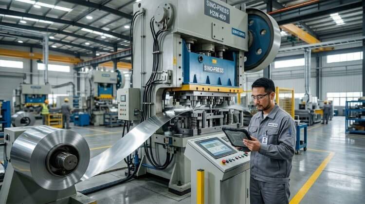
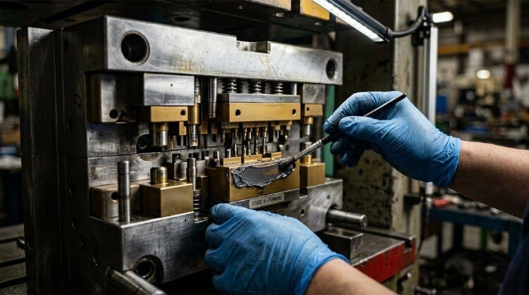
Tooling Design in Stainless Steel Stamping Controls Production Efficiency
Tooling architecture establishes the absolute limits of speed, quality, and reliability for the entire stamping operation. If a die is not engineered specifically to handle the harsh, abrasive realities of stainless steel, production will bleed money through constant interruptions.
Progressive Dies
Progressive dies feed a continuous strip of stainless steel through multiple forming stations with a single press stroke. Engineered for maximum speed and volume, this automated setup eliminates manual part handling and reduces cycle times to seconds.
However, the initial engineering and machining investments for these complex tools are substantial and require rigorous justification based on order volume.
Stage Tooling
For medium production runs, stage tooling breaks the forming sequence into isolated stations. Operators manually transfer the stamped blanks between distinct punching, bending, or drawing operations.
This approach drastically reduces upfront capital expenditure compared to progressive dies. The trade-off is a significantly longer cycle time and a higher per-part labor burden applied to your quote.
Tool Steel Selection
Standard D2 tool steel often degrades rapidly when blanking or forming tough stainless alloys. The severe impact and friction cause conventional steels to micro-chip or lose their cutting clearance prematurely.
For high-wear punch and die sections, engineers must specify powder metallurgy high-speed steels, such as CPM 10V. These advanced alloys resist chipping and hold critical dimensional tolerances significantly longer under extreme press tonnage.
PVD Coatings
Running bare tool steel against stainless sheet metal guarantees galling. Applying Physical Vapor Deposition (PVD) or Thermal Diffusive (TD) coatings, such as TiCN, is mandatory to isolate the die surface and reduce the coefficient of friction.
While a bare D2 die might require tearing down for polishing after just 10,000 hits, a TiCN-coated CPM 10V punch can push maintenance intervals past 100,000+ hits, drastically increasing machine uptime.
EP Lubrication
Standard stamping oils simply vaporize under the localized heat and severe friction generated by stainless steel. Once the lubricant boundary layer fails, tool wear accelerates exponentially.
Extreme-Pressure (EP) lubricants, formulated with active sulfur or chlorine additives, are absolutely critical. These compounds react under heat to form a sacrificial chemical barrier, preventing direct metal-to-metal cold welding during aggressive stretch-forming and deep drawing cycles.
In-Die Sensors
A snapped punch or a pulled slug can obliterate a progressive die in milliseconds. Relying on operator observation is completely inadequate for high-speed stamping lines.
Integrating acoustic and pressure in-die sensors allows the press logic to monitor the micro-tonnage of every single stroke. If a sensor detects a misfeed or a material fracture, the controller triggers an immediate emergency stop before catastrophic tool damage occurs.
Volume Forecasts Dictate the Manufacturing Strategy
Procurement strategy must align strictly with the forecasted production volume. Matching the fabrication method to the product lifecycle is the only reliable way to control the true amortized cost per part.
Low-Volume Production
For initial pilot runs of 50 to 500 parts, authorizing hard stamping tooling is a misallocation of capital. The die amortization would artificially inflate the piece price beyond acceptable limits.
Instead, we execute a hybrid manufacturing approach: pairing CNC laser cutting for flat pattern development with precision press brake forming to deliver functional prototypes with zero hard tooling investment.
Progressive Die Economics
Once order volumes scale past 10,000 to 20,000 pieces, the economics shift heavily in favor of progressive die stamping. The automated strip-feeding compresses cycle times down to fractions of a second per part.
Our engineering team routinely maps out the exact break-even point between stage tooling and progressive dies, ensuring your capital investment strictly aligns with your long-term demand curve.
Tooling Investment
Procurement teams must validate tooling Return on Investment (ROI) against realistic long-term forecasts. A $30,000 to $50,000 capital expenditure for a progressive die pays for itself rapidly at an annual run rate of 500,000 units.
Conversely, if a product is entering an untested market with volatile demand, executing the launch via stage tooling mitigates financial risk until order volumes stabilize.
Scrap Rate
Stainless steel alloys carry a heavy raw material premium; therefore, scrap generation directly erodes profit margins. Progressive dies inherently produce higher scrap rates due to the necessary carrier strip that advances the blank through the stations.
However, engineering the strip layout to improve material utilization by even 2% to 3% yields massive cost reductions over the lifespan of a high-volume program.
Conclusion
Stamping stainless steel is a highly controlled system engineering discipline, not a brute-force press operation. Long-term production stability depends entirely on the rigorous alignment of part geometry, material grade, and advanced tooling architecture.
Executing Design for Manufacturability (DFM) adjustments during the early prototype phase is the most effective lever for permanently stripping out manufacturing costs. Freezing a flawed design forces toolmakers into building overly complex, high-maintenance dies simply to fight poor geometry on the floor.
With over 10 years of industrial experience scaling projects from rapid prototyping directly into mass manufacturing, the engineering team at TZR understands these critical operational turning points.
Stop relying on trial and error at the press. Send us your 3D CAD models or STEP files. We will conduct a strict DFM review to identify severe springback risks, calculate forming tonnages, and optimize your blank layout before you commit a single dollar to hard tooling.