
 English
  Spanish
  German
  Russian
  Italian
  French
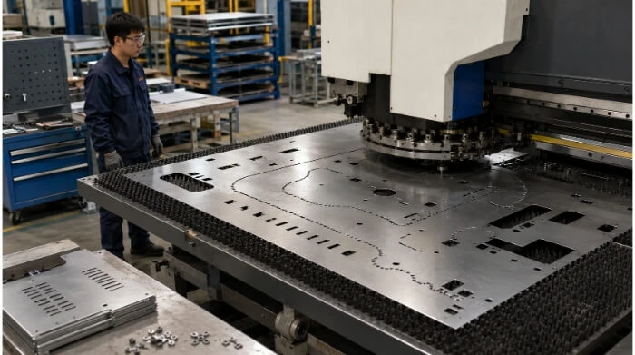
Nibbling in sheet metal is a cutting process that creates complex contours by making a series of closely overlapping punch hits. It is a highly versatile, cost-effective method for low-volume production and prototyping because it eliminates the need for expensive custom stamping dies.
While it offers immense geometric flexibility without dedicated tooling, the overlapping nature of the punch inherently leaves a textured, scalloped edge. For design engineers and procurement teams, the decision to use this method ultimately comes down to balancing initial tooling budgets against final edge quality requirements.
This guide breaks down exactly when to choose this process over laser cutting, the core DFM (Design for Manufacturability) rules to ensure part stability, and how to accurately calculate the total landed cost for your next project.
| Item | Quick Answer |
| Best for | Changing profiles, internal openings and low-tooling production (<500 parts) |
| Main benefit | Flexible cutting without dedicated contour dies |
| Main limitation | Scalloped edges, burrs and repeated punch time |
| Typical thickness | Up to 3mm (Mild Steel), up to 6mm (Aluminum) |
| Main alternatives | Laser cutting, standard punching and stamping |
Understand How Nibbling Forms the Part
Mastering this process begins with understanding its physical mechanics. Let’s explore how overlapping punch hits shape the metal and influence the final edge texture.
Punch Hits and Profile Generation
Nibbling relies on the interaction between a punch, a die, and a stripping mechanism. The punch travels along a programmed CNC path, striking the material repeatedly. Each hit removes a small section of metal. By overlapping these adjacent hits, the machine gradually clears a continuous slot or contour.
Step-Over and Scalloped Edges
The overlapping nature of the process inherently leaves a textured edge. As a rule of thumb, the step-over distance is usually set between 10% and 25% of the punch diameter.
A smaller step-over (e.g., 10%) reduces the scallop height, creating a visually smoother cut. However, a smaller step-over increases the number of punch hits required to cover the same distance. More hits extend machine cycle time, accelerate tool wear, and increase processing costs.
Engineers must separate profile accuracy from edge smoothness. A CNC turret punch will execute the programmed path accurately, but the resulting cut will always possess a scalloped texture. A highly accurate CNC path does not mean a smooth edge.
Cold Cutting and Mechanical Distortion
Nibbling is a mechanical shearing process, meaning it cuts without generating heat. Consequently, the cut edge has no heat-affected zone (HAZ), avoiding the localized hardening or metallurgical changes associated with laser or plasma cutting.
However, mechanical shearing introduces physical stress. Engineers should account for the following mechanical processing risks:
- Dense, continuous punch hits can alter internal material stresses, which may compromise overall sheet flatness.
- Narrow webs and long, thin structures are prone to twisting or distortion.
- The constant movement of the sheet under the clamps and stripper pads may leave witness marks on the material surface.
CNC Nibbling and Hand Nibblers
It is necessary to clearly distinguish between two entirely different classes of equipment.
Hand nibblers are portable power tools. They are usually used for field modifications, maintenance work, rough cutouts, and low-volume field adjustments.
CNC turret punch nibbling utilizes industrial programmable equipment. It is specified for precise openings, repeatable production runs, and parts that integrate standard hole punching, nibbling, and sheet metal forming (like louvers) in a single automated setup. The tolerances, speed, and capabilities of these two methods are not comparable and should not be evaluated against the same standards.
Decide When Nibbling Fits the Job
Choosing the right manufacturing process dictates your project’s success and budget. Discover exactly when this technique outperforms laser cutting and standard stamping operations.
Part Geometry and Production Volume
The suitability of nibbling depends heavily on the part design and the production volume. The process becomes more cost-effective for prototypes and short-run production batches (typically under 500 parts) where amortizing custom stamping dies is not viable.
Suitable geometries include:
- Non-standard internal openings
- Large sweeping curves
- Parts with designs subject to ongoing revision
- Panels requiring both punched cutouts and formed features
Typical applications include electrical enclosure panels, HVAC components, machine guards, and prototype sheet metal brackets. Standard geometries—such as regular round holes, square cutouts, and standard slots—should always be processed with single-hit standard punches rather than nibbled.
Tolerance and Edge Requirements
When evaluating edge quality, distinguish between several different metrics:
- Profile tolerance
- Feature location
- Scallop height
- Burr height
- Sheet flatness
If a part design strictly requires a smooth cosmetic edge, a precision sealing surface, very small internal radii, or tight-tolerance mating cutouts, nibbling is usually the wrong choice. In these scenarios, the manual or automated grinding required to smooth the scalloped edge will normally negate any savings gained during primary processing.
Nibbling, Laser Cutting and Standard Punching
Selecting the right process requires matching the part’s primary feature requirements with the most efficient cutting method.
| Part Requirement | Preferred Process |
| Changing non-standard openings | Nibbling |
| Smooth and complex profiles | Laser cutting |
| Standard holes and slots | Standard punching |
| Long straight cuts | Shearing |
| Stable high-volume production | Stamping (>10,000 parts) |
Practical process selection also depends on material grade, sheet thickness, available factory equipment, and the required secondary finishing operations.
Punch-Laser Combination Processing
Modern manufacturing environments often use punch-laser combination machines to optimize production.
In a hybrid setup, work is divided based on tool efficiency. Standard holes, hardware knockouts, and formed features are completed by the punch head. Threads can often be tapped directly in the machine. Complex outer contours and edge profiles requiring a smooth finish are then processed by the laser. This approach keeps the sheet in a single setup, eliminating the need to move parts between machines and maintaining tight positional tolerances across all features.
Design Parts for Stable Nibbling
Smart engineering at the CAD stage prevents costly shop-floor failures. Review these essential design guidelines to ensure your components are both manufacturable and affordable.
Punch Size and Internal Radii
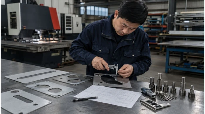
The diameter of the punch directly dictates the minimum internal radii and the level of contour detail achievable.
Engineers should define internal radii based on standard available punch sizes. A smaller punch can profile tighter corners and finer details, but it requires significantly more hits to cover a given perimeter. This increases machine time and accelerates tool wear, which directly inflates the per-part piece price. Conversely, a larger punch covers distance efficiently but cannot navigate tight internal geometry.
There is no universal minimum radius for all materials and machines. Furthermore, standard round holes, squares, and standard slots should always be dimensioned to match standard single-hit punches rather than being profiled via nibbling.
Feature Spacing and Weak Sections
The mechanical stress of repeated punching requires adequate material support. Designers must pay close attention to:
- The distance from an opening to the edge of the sheet
- The web thickness (the remaining material) between two adjacent cutouts
- Narrow, elongated slots
- Long, unsupported protrusions
- Openings located too close to a bend line
Punching in these areas often causes edge tearing, twisting of thin webs, localized distortion (oil-canning), and dimensional instability during subsequent bending operations.
💡 DFM Rule of Thumb: Keep feature-to-edge and feature-to-feature spacing at least 1.5t to 2.0t (t = material thickness). Anything less requires custom single-hit punch tooling to prevent edge blowout.
Material Grade and Sheet Thickness
Specifying a material involves understanding how different alloys respond to continuous mechanical shearing.
Aluminum (up to 6mm): Requires lower punching force, but soft grades are prone to surface indentations from the stripper pad, material adhesion (galling) on the punch, and rolled burrs.
Mild Steel (up to 3mm): Behaves predictably and serves as a stable baseline for most standard punched parts. Tool wear is moderate, and edge quality is generally consistent.
Stainless Steel (up to 2mm): Has high shear strength, which places severe stress on the machine and tooling. Nibbling stainless steel accelerates punch wear and causes severe localized work hardening along the scalloped edge. If the part requires secondary tapping (threading) near this edge, standard taps will likely snap. It may require specialized tooling or leaving extra material for CNC milling.
Coated Sheet: Pre-painted, galvanized, or PVC-coated sheets require strict shop-floor control to prevent the peeling of protective films, surface scratching from the machine’s brush table, and coating degradation directly at the sheared edge.
Burr Direction and Process Sequence
Every punched feature has a roll-over side and a break-out (burr) side. The direction of this burr affects V-die clearance during bending, weld fit-up, fastener installation, gasket sealing performance, and the evenness of surface treatments like powder coating.
⚠️ Assembly Warning: Always designate the “burr side” on the inside of bends (when possible) to prevent micro-cracking at the bend radius.
Engineers must anticipate the standard manufacturing sequence: Standard punching → Nibbling → Deburring → Bending → Welding → Surface finishing. During the design phase, clearly identify which edges are cosmetic surfaces, mating surfaces, and contact areas so the manufacturer can program the punch direction accordingly.
Control Edge Quality and Production Stability
Precision on the factory floor requires strict oversight of tooling and material behavior. Learn how optimal machine setup and deburring strategies guarantee consistent part quality.
Die Clearance and Tool Alignment
The clearance between the punch and the die determines the mechanics of the cut. It directly affects the required punching force, the ratio of the sheared zone to the fracture zone, burr height, tool life, and overall sheet distortion.
Die clearance is normally selected based on the material grade, sheet thickness, punch size, and the required edge condition—typically ranging from 15% to 20% of the material thickness for mild steel. Poor tool alignment or worn cutting edges will drastically alter this clearance, leading to uneven burrs, tearing rather than shearing, and dimensional drift along the profile.
Tool Wear and Lubrication
Nibbling subjects tooling to high-frequency impacts, often hundreds of hits per minute. This continuous friction causes:
- Cutting edge rounding and wear
- Higher localized heat
- Material adhesion (galling) to the punch flanks
- Progressively larger burrs
Common factory control methods include scheduled visual inspections, frequent regrinding, and updating tool length compensation in the CNC controller. Proper tool coatings (such as TiN or TiCN for harder alloys) and active lubrication—often minimal quantity lubrication (MQL)—are necessary to manage heat. Additionally, tooling used for stainless steel must be managed separately from tooling used for aluminum to prevent cross-contamination and premature wear.
Sheet Flatness and Slug Control
The physical management of the sheet and the punched waste (slugs) is critical for automated production.
Dense, repeated punch hits inject stress into the sheet, which can cause large panels to bow or lose flatness. Meanwhile, the process generates thousands of small slugs. If the stripping mechanism is unstable, a slug can be pulled back up out of the die (slug pulling). An uncontained slug resting on the die will either cause a catastrophic tool crash on the next hit or drag across the sheet, leaving deep scratches.
Factories control this by optimizing the punching sequence to distribute stress, using dies designed to prevent slug return, maintaining clean brush tables, and utilizing vacuum or conveyor slug removal systems.
Deburring and Inspection
A scalloped edge is a given, but the definition of an acceptable edge varies. Quality control teams must differentiate between instructions to:
- Remove loose burrs
- Break sharp edges
- Control maximum burr height
- Round exposed edges for safety
- Grind scalloped edges completely smooth
Cost Implication: Over-specifying edge requirements on non-contact areas can add 15% to 30% to the total part cost due to unnecessary manual labor.
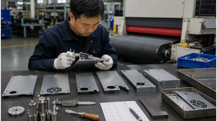
Common deburring treatments include manual filing, automated belt grinding, vibratory finishing, or in-machine deburring tools. Final inspection should verify profile dimensions, feature locations, scallop height, and sheet flatness. Dimensions must be verified after heavy deburring, as aggressive grinding can alter the final profile geometry. Concealed edges, internal assembly edges, and exterior cosmetic edges should never be evaluated against the same acceptance criteria.
Calculate Cost and Prepare the RFQ
True part cost extends far beyond the raw hourly machine rate. Follow these procurement tips to accurately evaluate quotes and submit bulletproof manufacturing requests.
Punch Count and Cycle Time
Machine time during nibbling is directly driven by the total contour length, punch diameter, step-over distance, number of internal openings, curve complexity, material thickness, and the specific machine’s hit rate.
To understand how engineering choices impact cost, consider this practical case study of cutting a 200mm straight slot using a standard 10mm diameter punch:
| Step-Over Setting | Hits Required | Machine Cycle Time | Scallop Condition | Post-Processing Required |
| 20% (2mm) | 100 hits | Slower | Minimal texture | Light deburring (fast) |
| 50% (5mm) | 40 hits | Faster | Pronounced scallops | Heavy manual grinding (slow) |
Cost Takeaway: Optimizing for the absolute fastest CNC machine time (using a large step-over) often results in a deeply scalloped edge. If the drawing then requires that edge to be perfectly smooth, the manufacturer must use expensive manual grinding labor, which ultimately makes the part more expensive than if it were nibbled slowly with a fine step-over.
Setup, Tooling, and Finishing Costs
When evaluating competing quotes, ensure the manufacturer is accounting for the complete production cycle. A comprehensive cost breakdown should include:
- CNC programming and machine setup
- Material utilization: Highly irregular nibbled shapes can result in poor nesting efficiency, increasing the scrap rate and per-part material cost.
- Actual punching time
- Tool wear amortization (especially critical for stainless steel)
- Deburring and manual edge finishing labor
- Surface finishing prep (if required)
- First Article Inspection (FAI)
Buyers should always compare the total landed cost of a fully qualified, finished part rather than focusing strictly on the raw punching rate.
CAD, Material, and Critical Dimensions
A precise quote requires clean data. When submitting an RFQ, provide a 3D STEP file alongside a DXF or DWG flat pattern, backed by a fully dimensioned PDF drawing.
Clearly state the material grade, sheet thickness, required surface condition, grain direction (critical for stainless steel cosmetics or bending), and whether protective film must be maintained during processing.
💡 Procurement Pro Tip: Designing around standard local sheet thicknesses (e.g., 1.5mm, 2.0mm, 3.0mm) rather than obscure gauges prevents minimum order quantity (MOQ) surcharges and significantly reduces material lead times.
⚠️ CAD Hygiene Warning: When exporting DXF flat patterns, ensure all contours are fully closed. Files containing duplicate lines, broken contours, overlapping geometry, or unclear layer assignments cause CNC programming errors, leading to engineering holds and delayed production.
The 2D drawing must explicitly identify:
- Critical assembly dimensions and hole locations
- Sealing areas (where scallops may cause leaks)
- Cosmetic edges (visible to the end-user)
- Contact edges (where sharp burrs pose a safety hazard)
Quantity, Edge, and Inspection Requirements
Volume dictates the manufacturing strategy. Your RFQ should outline the prototype quantity, the expected first production run, annual demand, and repeat order frequency.
Vague edge requirements are the leading cause of pricing disputes and rejected batches. Instead of asking for “clean edges,” use definitive engineering language on the drawing:
- Scalloped edge acceptable
- Loose burrs removed
- Break all sharp edges
- Maximum burr height: 0.1mm
- Smooth ground edge required
For critical components, explicitly request your quality control requirements upfront. This may include a First Article Inspection (FAI) report, dimensional data logs, physical edge sample approvals before full production, or functional fit checks.
Conclusion
Nibbling works best when a part requires flexible geometries, internal cutouts, and punched features without the high upfront cost of dedicated contour tooling. It is highly cost-effective for prototypes and short-run production. However, it becomes less attractive when the design mandates perfectly smooth cosmetic edges, tight contour tolerances, or long, straight cuts that are better suited for lasers or shears.
Not sure whether your part should be nibbled, punched, or laser cut?
Send us your CAD files, material specifications, and order quantity. Our engineers will perform a manual DFM review of your edge requirements and send you a cost-optimized quote within 24 hours.