
 English
  Spanish
  German
  Russian
  Italian
  French
Welding tube and pipe involves either manufacturing hollow sections from flat steel strip or joining pre-formed profiles into structural frames and fluid systems. Fabrication primarily relies on TIG (GTAW) for high-precision joints and MIG (GMAW) for heavy structural applications.
Beyond the welding process itself, reliable joint integrity depends heavily on base material, wall thickness, joint fit-up, and heat input control. This guide explains how to select a suitable fabrication method, design practical joints, and manage thermal distortion.
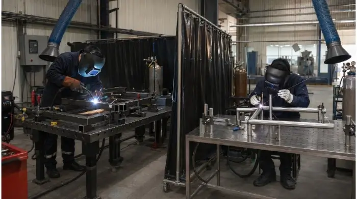
Define the Tube, Material, and Service Conditions
Process selection must be based on the raw material and the service environment of the final product. Evaluating the base material properties and operating conditions before choosing a welding method limits the risk of failure in the field.
Tube, Pipe, and Hollow Sections
The industry uses different naming conventions depending on the application. “Tube” is generally measured by exact outside diameter (OD) and wall thickness, whereas “pipe” is specified by Nominal Pipe Size (NPS) and Schedule. Furthermore, round profiles distribute stress evenly for pressure applications, while square and rectangular hollow sections introduce specific fit-up variations and stress concentrations at the corners.
Because of these geometric differences, acceptance criteria vary significantly based on the end use. Structural assemblies are primarily inspected for load-bearing capacity and dimensional alignment under codes like AWS D1.1 or ASTM A500. Conversely, fluid piping requires strict verification of root penetration and leak-tightness per standards like ASME B31.3.
Welded, Seamless, and DOM Tube
Welded tube is formed from flat steel strip, which provides highly consistent wall thickness but leaves a longitudinal weld seam. Seamless tube is extruded or pierced, eliminating the seam entirely but often resulting in greater wall thickness variation. Drawn Over Mandrel (DOM) is typically a welded tube subjected to a secondary cold-drawing process to improve dimensional tolerances, surface finish, and homogenize the weld area.
Selecting between these options is not simply a matter of assuming one is stronger. Welded tube typically costs 20% to 30% less and is readily available in custom profiles, making it ideal for general fabrication. Seamless tube, however, is usually mandated by specific high-pressure or high-temperature engineering codes where longitudinal seams are strictly prohibited.
Tube-Mill Seam Processes
For welded raw materials, the longitudinal seam is formed at the tube mill long before it reaches the fabrication shop. High-Frequency Induction (HFI) and Electric Resistance Welding (ERW) are the standard methods for continuous carbon steel production. Laser welding is more frequently used for thin-wall or specialty alloy tubes to tightly control the heat input during manufacturing.
These primary manufacturing processes leave an internal weld bead, known as flash. Flash-in (FI) tube is acceptable for standard static structures, but flash-controlled or flash-removed tube is absolutely required if the application involves fluid flow, internal wiring, or tight-radius CNC mandrel bending. Additionally, inline seam annealing is frequently applied at the mill to relieve residual stresses and restore ductility to this weld zone.
Material, Wall Thickness, and Service Conditions
Wall thickness defines the maximum allowable heat input, while service conditions—such as pressure, fatigue loading, and outdoor exposure—determine the necessary penetration and post-weld finishing.
| Material | Typical Application | Main Welding Risks and Considerations |
| Carbon Steel | Structural frames, machine bases, heavy equipment | Hardness variations in the HAZ; potential for cold cracking in walls over 0.500″; requires rust prevention. |
| Stainless Steel | Sanitary lines (ASME BPE), food processing, corrosive fluids | Susceptible to heat tint and oxidation; lack of back-purging causes internal “sugaring,” leading to immediate rejection. |
| Aluminum | Lightweight structures, aerospace, transport equipment | High thermal conductivity demands rapid heat input; prone to severe softening in the HAZ and significant distortion. |
| Galvanized Steel | Outdoor structures, handrails, agricultural frames | Zinc coating causes weld porosity and toxic fumes; requires mechanical coating removal before welding and recoating afterward. |
| Alloy Steel | High-pressure piping, specialized tooling | Often requires strict preheating and Post-Weld Heat Treatment (PWHT) to manage cooling rates and prevent cracking. |
Match the Welding Process to the Application
Once the material and service conditions are defined, the next step is selecting the fabrication process to join the pre-formed tubes into assemblies.
MIG/MAG for General Tube Fabrication
Gas Metal Arc Welding (MIG/MAG) works well for carbon steel pipe racks, machine frames, and general structural assemblies in medium to high-volume production. Its primary advantage is a high deposition rate (typically 3 to 8 lbs/hr depending on wire diameter), which makes it highly cost-effective for fabricating long, continuous joints on thicker materials.
However, MIG introduces higher overall heat input and generates weld spatter. On thin-wall tubing (under 0.065″), aggressive MIG parameters frequently cause burn-through and distortion. Furthermore, the hidden labor costs associated with post-weld spatter removal and grinding for cosmetic finishes can quickly offset the time initially saved during the arc-on phase.
TIG/GTAW for Thin and Clean Welds
Gas Tungsten Arc Welding (TIG/GTAW) is usually specified for thin-wall stainless steel, aluminum assemblies, sanitary tubing, and precision joints requiring an unblemished appearance. TIG provides precise control over the weld pool, significantly reducing the risk of burn-through while producing a clean, spatter-free bead. While the arc-on time is noticeably slower (often under 5 inches per minute manually), it largely eliminates the need for post-weld grinding.
The primary limitations of TIG welding are its slow travel speed and the requirement for highly skilled operators. Moreover, TIG has virtually zero tolerance for poor joint fit-up. Gaps or misalignments that a MIG process could easily bridge will cause autogenous TIG welds to fail or require excessive manual filler metal additions.
Laser and Orbital Welding for Repeatable Production
Laser welding is utilized for precision thin-wall assemblies where minimizing the Heat-Affected Zone (HAZ) is critical. Similarly, orbital TIG welding is specifically designed for round tube butt joints, commonly mandated in high-purity fluid and pharmaceutical systems to ensure 100% repeatable and traceable weld parameters.
It is important to note, however, that implementing automation does not automatically reduce overall production costs. The economic viability of laser and orbital systems depends heavily on high production volumes, the cost of precision fixturing, programming time, and the shop’s ability to maintain near-perfect tolerances on incoming cut tubes.
Process Selection Table
| Process | Typical Use | Main Advantage | Main Limitation |
| MIG/MAG | Carbon steel frames and general fabrication | High deposition rate; suited for volume production. | Spatter cleanup and heat input management. |
| TIG/GTAW | Thin-wall stainless, aluminum, cosmetic joints | Precise pool control; clean and spatter-free. | Slower travel speed; strictly requires tight joint fit-up. |
| Laser | Precision thin-wall tube assemblies | Minimal HAZ; extremely high repeatability. | High equipment cost; zero tolerance for joint gaps. |
| Orbital TIG | High-consistency round tube butt welds | Stable, traceable parameters for critical piping. | Requires extensive programming and exact tube prep. |
| Stick/FCAW | Thick-wall pipe and field installation | Effective outdoors; tolerates wind and rust. | Significant post-weld slag cleanup required. |
When matching a process to your application, follow this evaluation sequence:
- Review base material and wall thickness to eliminate incompatible methods.
- Evaluate the required visual appearance and acceptable post-weld finishing costs.
- Confirm penetration requirements and fluid sealing standards.
- Assess if the production volume justifies the fixturing and setup costs for automation.
Design Joints for Welding and Secondary Forming
The design of a tube joint directly dictates assembly time, penetration depth, distortion levels, and ultimately, production cost. A joint that looks perfectly flush in a CAD model can be completely un-weldable on the shop floor if edge preparation, fit-up tolerances, and torch accessibility are not properly engineered.
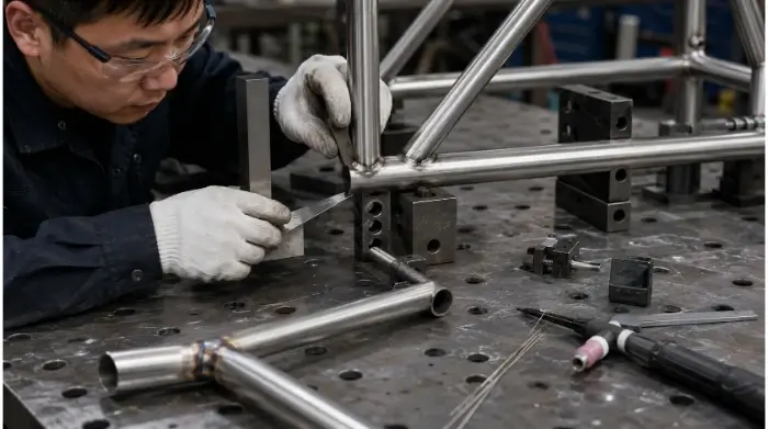
Joint Type and Edge Preparation
Different joint configurations require varying levels of machining, fixturing, and operator skill.
- Butt Joint: End-to-end connection. Allows for full-penetration welds critical for fluid piping, but requires exacting cut lengths and root alignment.
- Fillet Joint: Formed when one tube meets another perpendicularly (without penetrating it). Easy to assemble and fixture, but results in partial joint penetration.
- Miter Joint: Angled cuts (usually 45 degrees) joined to form corners. Requires precise band-sawing and deburring; sharp inner corners easily lead to burn-through.
- Fishmouth / Branch Joint: A profiled tube end saddled over a main run. Requires CNC tube laser cutting or specialized hole-saws. The root gap varies continuously around the perimeter, making robotic automation difficult.
- Sleeve Joint: One tube slides inside an expanded tube. Highly forgiving on length tolerances and alignment, often used in brazed assemblies and structural frames.
- Tube-to-Plate Joint: Joining thin-wall tube to a thick base plate creates a massive heat-sink mismatch, increasing the risk of undercut on the tube side and lack of fusion on the plate side.
- Flange Connection: Butt or socket welded. The primary concern is managing thermal distortion to keep the machined flange face perfectly flat for sealing.
Root Gap, Fit-Up, and Alignment
Achieving a repeatable weld requires locking down several interdependent parameters: wall thickness, bevel angle, root face (land), and root opening (gap). A common engineering misconception is that a 45-degree bevel is a universal standard. In reality, thin-wall tubes (under 0.120″) often require no bevel at all for a square-groove TIG weld. For thicker pipes (e.g., Schedule 40), a 37.5-degree bevel is standard per ASME codes to balance torch access with minimal filler metal volume.
Fit-up variations immediately impact weld quality. A root gap that is too wide forces the welder to add excessive heat to bridge the opening, dramatically increasing burn-through risk. Conversely, a gap that is too tight restricts filler metal flow, resulting in Lack of Penetration (LOP).
Furthermore, joint misalignment (high-low mismatch) is not just a cosmetic issue. In structural frames, it creates stress concentrations. In sanitary fluid lines, internal mismatch creates flow turbulence and bacterial traps, leading to immediate rejection under ASME BPE inspection. Assemblies must be visually re-checked for angle and centerline alignment after initial tacking, as the tack welds themselves will pull the joint out of square.
Welding Access, Tacking, and Fixtures
If the welder cannot physically access the joint, the weld will fail. Before releasing a design, engineers must verify that the welding torch—including the gas cup and tungsten stick-out—can navigate the geometry. Acute internal angles (less than 60 degrees) often prevent the gas nozzle from seating properly, leading to poor shielding gas coverage and porosity.
Tooling and fixturing play an equally critical role. Fixtures must provide accurate locating faces while allowing access for tack welding. Tacks should be placed symmetrically to distribute initial shrinkage stresses evenly. Furthermore, bulk assemblies must allow room for the part to be rotated; welding strictly out-of-position (e.g., overhead) is slower, more expensive, and more prone to defects than welding in the flat or horizontal position.
Weld Seam Position During Tube Bending
When welded tubing is subjected to secondary CNC rotary draw bending, the position of the longitudinal mill seam becomes a critical variable. Tight bend radii and thin walls are highly sensitive to seam placement.
Generally, manufacturers avoid placing the weld seam on the intrados (the inside radius under maximum compression) or the extrados (the outside radius under maximum tension), as the weld area is slightly harder and less ductile, increasing the risk of wrinkling or splitting.
Placing the seam on the “neutral axis” (the sides of the bend) is best practice. However, this is not an absolute rule. For complex parts with multiple bends in different planes (3D bending), it is geometrically impossible to keep the seam on the neutral axis for every bend. In these cases, trial bends and destructive cross-sectioning are mandatory. Even DOM tubing, which has a highly homogenized seam, requires bend verification before full-scale production.
Control HAZ, Distortion, and Weld Defects
Controlling the welding process is less about textbook metallurgy and more about managing practical material responses on the shop floor. Heat affects more than just the molten pool; it alters the surrounding base metal and physically pulls the assembly out of tolerance.
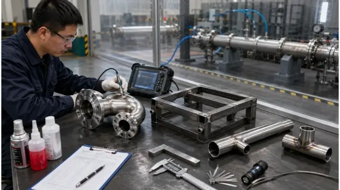
Heat Input and Material Response
The Heat-Affected Zone (HAZ) is the area of base metal that did not melt, but whose mechanical properties and microstructure were altered by the intense heat. While a highly concentrated heat source (like a laser) produces a narrower HAZ, a small HAZ does not automatically guarantee a qualified joint. The material’s specific response to heat dictates the outcome:
- Carbon Steel: Rapid cooling in thicker walls can trap hydrogen and cause cold cracking. Preheating may be required.
- Stainless Steel: High heat input burns away chromium, leaving dark heat tint (oxidation). Prolonged time in the 800°F–1500°F range causes carbide precipitation (sensitization), permanently degrading local corrosion resistance.
- Aluminum: Welding severely degrades the temper. For instance, the HAZ of a 6061-T6 aluminum tube can lose up to 50% of its original yield strength, requiring post-weld artificial aging to recover structural integrity.
- Galvanized Steel: Heat vaporizes the zinc coating, creating toxic fumes and severe weld porosity if the coating is not ground off prior to welding.
Welding Sequence and Fixture Control
Distortion is the physical result of the weld metal shrinking as it cools. Rather than simply clamping the tubes tighter—which locks in massive residual stresses and causes premature fatigue cracking—distortion should be managed through controlled heat distribution.
Standard shop-floor techniques include skip welding (back-stepping), alternating welds on opposite sides of a joint, and utilizing symmetrical tacking. Breaking a long, continuous weld into shorter, staggered segments allows the surrounding metal to act as a heat sink, preventing the tube from bowing. Fixtures should hold the correct geometry but allow for micro-movements to relieve shrinkage stress during the cooling phase.
Common Defects and Corrective Actions
Visual and structural defects are usually traced back to improper parameter settings or poor fit-up. The table below outlines common tube welding defects and the practical shop-floor responses required to fix them.
| Defect | Likely Cause | Production Response |
| Burn-through | Heat input too high or root gap too wide. | Reduce amperage/wire feed; tighten fit-up tolerances. |
| Porosity | Surface contamination or loss of shielding gas. | Degrease tube ends; check gas flow rate and torch angle. |
| Lack of Fusion | Insufficient heat input or incorrect torch angle. | Increase amperage; ensure arc is directed at the root, not the sidewall. |
| Undercut | Current too high or travel speed too fast. | Optimize heat input; add sufficient filler metal to the toes. |
| Distortion | Uneven heat distribution. | Implement skip welding; optimize tack placement and fixturing. |
| Misalignment | Insufficient fixturing or thermal pulling. | Improve fixture rigidity; verify dimensions after tacking. |
| Heat Tint (SS) | Insufficient gas shielding or excessive heat. | Implement ID back-purging; use chemical passivation post-weld. |
For structural applications, codes like AWS D1.1 provide specific acceptance criteria—for example, limiting undercut depth to 1/32 inch (0.8 mm) for primary members. Mentioning these limits in your RFQ prevents both costly over-processing by the vendor and unexpected rejections.
Post-Weld Cleaning and Heat Treatment
Post-weld processing is a major cost driver that is frequently overlooked in the design phase. Depending on the material and application, post-weld requirements may include spatter removal, mechanical blending (grinding), pickling, and passivation (e.g., per ASTM A380/A967 to restore stainless steel’s passive layer).
Specifying “flush grinding and polishing” for cosmetic joints can easily consume 3 to 5 times more labor hours than the welding process itself. Engineers should only request mechanical blending when strictly necessary for mating surfaces or sterile environments.
It is also important to clarify that not all welded tube assemblies require Post-Weld Heat Treatment (PWHT). While inline seam annealing is common during raw tube manufacturing, full-body stress relief or solution annealing of a finished structural weldment is usually reserved for highly critical, thick-wall alloy piping. For general stainless steel frames, the focus is strictly on oxide removal and corrosion resistance recovery.
Production Example: Thin-Wall Stainless Tube Frame
Consider a real-world production adjustment for a sanitary equipment frame built from 1.5″ x 0.065″ 304L stainless steel square tubing.
Initially, the design called for long, continuous fillet welds around the base plates. The concentrated heat input caused the thin-wall tubing to bow inward by nearly 3 degrees and generated severe black heat tint. To solve this, the shop floor adjusted the sequence: they increased the number of rigid tack welds, switched from continuous passes to alternating 2-inch stitch welds, and utilized simple aluminum heat-sink blocks in the fixture.
This engineering change brought the frame back into strict dimensional tolerance, eliminated the bowing, and cut the post-weld chemical passivation time in half.
Conclusion
Reliable tube and pipe welding starts before the first weld is made. Material grade, wall thickness, joint fit-up, weld access, heat input, and inspection requirements must work together. A suitable welding process cannot correct a joint that is difficult to assemble or a drawing that leaves critical requirements unclear.
MIG, TIG, laser, and orbital welding each have clear advantages, but no single process fits every project. The right choice depends on the tube material, weld location, production volume, cosmetic requirements, and whether the finished assembly must carry pressure or prevent leakage. Welding sequence, fixtures, and post-weld treatment are equally important when controlling distortion and maintaining consistent dimensions.
Need Help With a Tube or Pipe Welding Project?
Send us your 2D drawings, 3D models, material requirements, and expected quantities. Our engineering team can review the joint design, welding access, distortion risks, inspection needs, and production sequence before quoting.