CNC Machining Materials: How to Choose Metals and Plastics
Kevin Lee
Published:
CNC machining materials
The best CNC machining materials balance mechanical performance with high machinability to reduce costs. Standard choices include Aluminum 6061 for general lightweight parts, Stainless Steel 304/316 for corrosion resistance, POM (Acetal) for low-friction plastics, and Brass C360 for high-speed precision manufacturing.
In CNC manufacturing, the raw material price often represents only 20% of your final quote. The remaining 80% is driven by how fast a machine can cut it, how quickly tools wear out, and the risk of scrap. Unfortunately, over-specifying a material—like choosing aerospace-grade titanium when standard aluminum would work—is the fastest way to inflate your budget and extend your lead time.
Relying purely on material spec sheets is a quick way to overpay for manufacturing. Here, we evaluate standard CNC metals and plastics based on how they actually cut, wear tools, and impact your final price. You will learn how to balance part functionality with shop-floor realities to lock in the lowest-risk material.
Quick Material Selection Table
Part Requirement
Common Starting Point
Why It Fits
Main Risk
General-purpose lightweight parts
Aluminum 6061-T6
✅ Good balance of strength, cost, and 1.0X baseline machinability.
⚠️ Lower yield strength than aerospace alloys.
High-strength structural parts
Alloy Steel 4140
✅ High fatigue strength and toughness.
⚠️ Requires heat treatment and coating to prevent rust.
Corrosive environments
Stainless Steel 316/316L
✅ Resists chlorides and marine environments.
⚠️ Gummy and work-hardens; 2.5X machining time.
Low-friction components
POM (Acetal/Delrin)
✅ Low coefficient of friction, highly stable.
⚠️ Low continuous operating temperature.
Electrical & thermal components
Copper C110
✅ Maximum electrical and thermal conductivity.
⚠️ Extremely gummy; requires manual deburring.
Transparent parts
PMMA (Acrylic)
✅ High optical clarity.
⚠️ Brittle; highly prone to stress cracking.
High-temperature applications
PEEK
✅ Maintains mechanical properties at elevated heat.
⚠️ Extremely high raw material cost.
Note: The table provides starting points rather than final material recommendations. Geometry, tolerances, quantity, finishing, and certification requirements usually alter the final selection.
Define the Part Requirements Before Choosing a Material
Material selection must begin with the exact conditions the finished part must survive. Separate requirements into “must meet” and “preferred.” This prevents your team from paying for strength, corrosion resistance, or temperature thresholds that the application does not actually need.
Loads, Wear, and Service Life
Mechanical requirements dictate your starting material category. Evaluate static loads, sudden impact, fatigue from repeated stress, stiffness, friction, bearing pressure, and expected surface wear over the expected service life.
Tensile strength is not always the deciding property. A flexible bracket may be controlled entirely by stiffness. A rotating shaft usually fails due to fatigue or wear, not a lack of ultimate tensile strength. A sliding component depends more on friction and bearing pressure limits than on maximum load capacity.
Temperature, Corrosion, and Chemicals
Environmental exposure quickly narrows the available material list. Consider the continuous operating temperature, short thermal peaks, and expected thermal cycling. Note the difference between a material’s melting temperature and its safe continuous working temperature; a plastic may melt at 250°C but lose structural integrity at 100°C.
You must also assess exposure to moisture, salt, chlorides, oils, machining coolants, cleaning agents, and outdoor weather. Premium materials such as 316 stainless steel, titanium, or PEEK increase costs significantly. They are justified only when the working environment specifically demands their added performance.
Weight, Conductivity, and Appearance
Other functional requirements often eliminate unsuitable materials before detailed cost comparisons even begin. Strict weight limits usually rule out steels and copper alloys. If a part requires high electrical or thermal conductivity, aluminum and copper are the standard choices. If electrical insulation or magnetic transparency is required, plastics or non-magnetic metals must be specified. Color and cosmetic surface requirements also limit choices, as certain materials accept coatings and finishes better than others.
Compare Common CNC Metals by Grade
The table below outlines common metals. Actual finished cost depends on region, stock size, quantity, part geometry, specified tolerances, finishing, and inspection requirements. To provide a realistic baseline, we use Aluminum 6061-T6 as our 1.0X standard for relative machining time.
Aluminum 6061-T6 is the practical starting point for general CNC parts. It is widely stocked, machines efficiently, and accepts standard Type II and Type III anodizing consistently.
(Note: Aluminum 6082-T6 is the standard equivalent to 6061 in many European markets. Aluminum 5052 is typically reserved for formed and welded sheet metal parts; it is gummy and difficult to CNC machine cleanly.)
Aluminum 7075-T6 is specified when the application requires higher yield strength. However, 7075 is normally avoided in conventional welded structures due to its susceptibility to micro-cracking. Be aware that alloy grade, stock condition, and minor batch differences will affect the final anodized appearance.
Comparison: 6061-T6 vs. 7075-T6
Strength: 7075-T6 offers nearly double the yield strength of 6061-T6.
Machinability: Both machine well, but 7075 produces slightly shorter chips (1.2X machining time).
Welding: 6061 is readily weldable; 7075 is generally considered non-weldable.
Anodizing: 6061 takes clear and color anodizing well. 7075 often yields a darker or yellowish tint, especially in clear anodize.
Finished-Part Cost: 6061 is more available globally and results in a lower finished-part cost.
💡 Shop-Floor Case: Large Fixture Plate
Part Requirement: 500mm x 500mm x 15mm base plate holding ±0.05mm flatness.
Candidates: 6061-T6 plate vs. Cast Tooling Plate (MIC6).
Final Choice: Cast Tooling Plate (MIC6).
Rejected Option & Reason: 6061-T6 was rejected. Heavy face milling to reach the final thickness releases internal rolling stresses, causing the 6061 plate to warp out of tolerance immediately after unclamping. Cast plate provides stability in large, flat components.
Carbon and Stainless Steels
Low-carbon steel like 1018 works well for low-cost structural components, though it can produce stringy chips that slow down automated production. Alloy steel 4140 offers higher strength and toughness but must be specified by its condition (annealed, normalized, or pre-hardened) because the state directly affects both machining time and final part performance.
Stainless steels are usually chosen for corrosion resistance, but they introduce distinct machining risks. They tend to work-harden rapidly, meaning the material becomes harder as the tool cuts it. This accelerates tool wear and requires rigid workholding. 17-4 PH stainless steel is used for excellent strength and corrosion resistance, but drawings must specify the required condition (e.g., Condition H900) to dictate the necessary aging treatment.
Comparison: 303 vs. 304 Stainless Steel
303 contains added sulfur, making it the easiest austenitic stainless steel to machine (1.6X machining time vs. 2.0X for 304). It is ideal for high-volume precision fittings. However, the sulfur reduces its corrosion resistance and makes it non-weldable. 304 is the safer choice when the part requires welding, forming, or exposure to mildly corrosive environments.
Comparison: 304 vs. 316 Stainless Steel
304 handles the needs of most general and food-grade equipment. However, in marine environments, chemical processing, or medical applications, the added molybdenum in 316 stainless steel is necessary to prevent pitting and defend against chloride exposure. 316 costs more raw and takes roughly 25% longer to machine than 304.
Brass, Copper, and Titanium
C360 brass is an extremely efficient material for CNC machining. It produces short, brittle chips, leaves excellent surface finishes, and extends tool life. At high volumes, the rapid machining speed (0.8X) often offsets the higher raw material cost.
C110 copper is necessary for parts needing maximum electrical or thermal conductivity. While physically soft, it creates severe machining headaches. Copper is gummy, adheres to cutting tools, retains heat, and pushes material rather than cutting cleanly. This leads to heavy burr formation.
💡 Shop-Floor Note: Never design deep blind threaded holes in C110 copper unless absolutely necessary. Taps snap easily in this gummy material, driving up scrap rates and your final piece price. Manual deburring time alone can frequently double the cost of a copper part.
Ti-6Al-4V offers an excellent strength-to-weight ratio but introduces specific thermal challenges. Titanium has very low thermal conductivity. Instead of the chip carrying the heat away (as with aluminum), heat concentrates at the cutting edge. This causes rapid tool wear and requires lower cutting speeds (3.5X to 4.0X machining time) and high-pressure coolant. Clarify that titanium does not automatically require five-axis machining. Machine configuration depends entirely on part geometry, tool access, and the number of setups required, not the material itself.
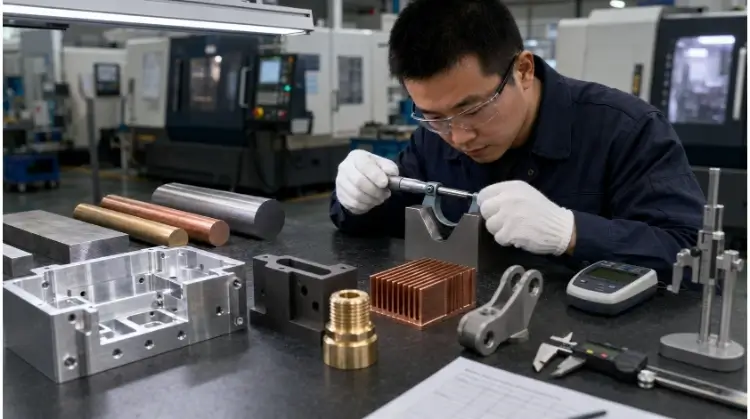
Five Metals on the Inspection Bench
Choose CNC Plastics by Stability and Working Environment
Plastics behave completely differently than metals under a cutting tool. When specifying plastic components, engineers must change their baseline assumptions regarding clamping force, heat control, achievable tolerances, and inspection conditions.
Plastic and Grade
Dimensional Stability
Moisture Sensitivity
Temperature Resistance
Main Machining Risk
Typical Uses
POM (Acetal)
High
Very Low
Up to 85°C
Can warp if internal stock stress is high.
Gears, bearings, precision spacers
Nylon (PA6/PA66)
Low
High (Absorbs water)
Up to 90°C
Swells in high humidity; stringy burrs.
Wear pads, high-friction sliders
ABS
Moderate
Low
Up to 80°C
Deflects easily under clamping pressure.
Prototyping, electronic housings
Polycarbonate (PC)
Moderate
Low
Up to 115°C
Heat buildup causes surface smearing.
Impact shields, transparent covers
Acrylic (PMMA)
High
Low
Up to 80°C
Extremely brittle; chips easily at edges.
Light guides, optical components
PTFE (Teflon)
Very Low
Zero
Up to 260°C
Creeps under pressure; difficult to hold tolerances.
Chemical seals, low-friction seats
PEEK (Unfilled)
Very High
Very Low
Up to 250°C
Requires sharp tooling; high raw material cost.
Medical devices, aerospace insulators
Acetal, Nylon, and ABS
POM (Acetal) is often the most practical starting point for precision plastic components. It offers high stiffness, low friction, excellent dimensional stability, and predictable machining behavior.
(Note: “Delrin” is a specific brand name for acetal homopolymer, POM-H. While POM-H offers slightly higher mechanical strength, acetal copolymer, POM-C, is generally more resistant to centerline porosity and chemical breakdown.)
Nylon provides excellent strength, impact resistance, and wear resistance. However, its major limitation is moisture absorption. A precision Nylon part machined perfectly to spec in a dry factory can absorb ambient moisture during weeks of ocean freight, arriving at your assembly line out of tolerance.
ABS provides a low-cost option for functional prototyping, but it requires careful machining. Because ABS is relatively soft and holds internal stress, the heat from the cutting tool and the clamping force from the vise can cause the part to deflect. Once unclamped, the material springs back, pushing critical dimensions out of spec.
💡 Shop-Floor Case: Precision Spacer
Part Requirement: 10mm thick spacer with a ±0.02mm bearing bore tolerance, operating in an outdoor, high-humidity environment.
Candidates: Nylon PA6 vs. POM-C.
Final Choice: POM-C.
Rejected Option & Reason: Nylon was rejected. While slightly cheaper and highly wear-resistant, its high moisture absorption meant the ±0.02mm bore would swell and bind the bearing in humid conditions. POM-C held the tight tolerance and remained dimensionally stable regardless of weather.
Polycarbonate, Acrylic, and PTFE
When applications require transparency, Acrylic (PMMA) and Polycarbonate (PC) are the standard choices. Acrylic provides superior optical clarity but is highly brittle. It is prone to stress cracking and edge chipping if feed rates and cutting speeds are not strictly controlled.
Polycarbonate offers massive impact resistance compared to Acrylic. However, PC is sensitive to heat buildup during machining, which can smear the surface finish and introduce residual stresses that alter the part’s final dimensions.
PTFE (Teflon) is chosen for extreme chemical resistance and nearly zero friction. While the material cuts easily, PTFE creeps (deforms) continuously under physical pressure and thermal changes. It is exceptionally difficult to hold PTFE within tight tolerances during both machining and final inspection.
PEEK, PEI, and High-Performance Plastics
High-performance plastics like PEEK and PEI (Ultem) carry very high raw material costs. They are justified only when the application strictly requires continuous high working temperatures (up to 250°C), aggressive chemical resistance, low outgassing in vacuums, repeated steam autoclave exposure, or specific electrical performance.
Adding glass or carbon fibers to PEEK drastically increases its stiffness. However, these abrasive fillers rapidly wear down standard carbide cutting tools. Heavy machining on filled PEEK also generates significant internal stress, often requiring intermediate annealing cycles (baking the plastic in an oven mid-process) to prevent the part from twisting before the final finishing passes.
⚠️ Compliance Note:
Do not assume that standard PEEK or PEI stock is automatically medical-grade or aerospace-approved. The stock production method and resin source matter. If your project requires regulatory compliance, the required commercial grade, material test reports, and lot traceability must be explicitly specified before quoting.
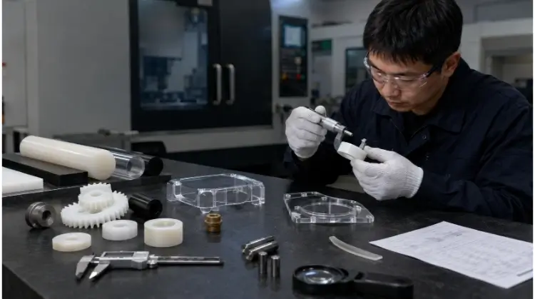
Precision Plastic Parts Under Dimensional Inspection
Evaluate Machining Risk, Supply, and Finished-Part Cost
Selecting a material by looking only at the raw price per kilogram is a common procurement mistake. To evaluate true manufacturing viability, use this decision framework:
Finished Part Cost = Material + Setup + Machine Time + Tooling + Finishing + Inspection + Scrap Risk
Treat this as a selection framework rather than a fixed quotation formula. Avoid combining machinability ratings from different material suppliers unless you are certain they use the exact same reference material and test conditions.
Geometry and Dimensional Stability
Material stability heavily dictates setup requirements and scrap risks. Difficult geometries—such as thin walls, deep pockets, large flat surfaces, long unsupported shafts, and small threaded holes—magnify machining risk.
Heavy, uneven material removal releases residual stress trapped inside the stock. The exact same aluminum alloy may remain perfectly stable in a thick, blocky part, but distort completely after 80% of its mass is milled away to leave a thin-walled enclosure.
Consider the stability implications of your starting stock. Plate, extruded bar, tube, cast blocks, and forged blanks all react differently to un-clamping. If a part demands tight tolerances across a large surface, specifying a stress-relieved stock condition is critical.
Machine Time, Tooling, and Scrap
Production costs are directly driven by material hardness, toughness, thermal conductivity, work-hardening tendencies, and the presence of abrasive fillers.
A material that produces continuous, stringy chips requires slower cutting speeds and frequent stops to clear the machine, increasing labor time. A material that generates heavy burrs requires manual deburring, which introduces human error and increases scrap risk.
💡 Shop-Floor Comparison: Machining Internal Features
When machining intricate internal threads, POM (Acetal) chips cleanly and leaves sharp, burr-free edges directly off the CNC machine. Nylon, being tougher and more elastic, tends to fold or tear rather than shear. This leaves stringy burrs attached to cross-holes. The manual labor required to inspect and pick burrs out of every Nylon part often makes it more expensive per finished piece than POM, even though Nylon stock is cheaper.
Stock, Finishing, and Inspection
Standard stocked materials keep lead times short and minimum order quantities (MOQs) low. A widely available material like 304 stainless steel is far more practical for a five-piece prototype run than a specialized aerospace alloy that requires a minimum mill order and a 12-week procurement cycle.
When evaluating stock availability globally, specifying approved equivalent materials (e.g., allowing GB or DIN equivalents for ASTM standards) can cut material procurement time by weeks without sacrificing part performance.
Secondary processes also change the material equation. Anodizing, plating, passivation, heat treatment, and powder coating physically alter the part. You must account for how coating buildup or chemical material removal will affect bearing fits, threaded holes, sealing surfaces, and electrical contact areas.
Finally, controlled inspection adds cost. If a plastic material requires a 24-hour stabilization period in a temperature-controlled metrology lab before CMM measurement, or if a complex part requires custom inspection fixtures and full material traceability certificates, those overhead costs must be factored into your initial material selection.
Conclusion
The best CNC machining material is not automatically the strongest, the cheapest per kilogram, or the easiest to cut. It is the lowest-risk material that meets your part’s exact functional requirements and can be sourced, machined, finished, and inspected at an acceptable total cost.
Over-specifying drives up tool wear and raw material costs. Under-specifying leads to premature field failures. By aligning your material choice with shop-floor realities and clear RFQ documentation, you secure better pricing, faster turnarounds, and reliable components.
Ready to move from design to production?
Submit your CAD files and project details. Our engineers will run a fast Design for Manufacturing (DFM) review to verify your material selection and tolerances, ensuring you get the most cost-effective manufacturing strategy before we finalize your quote.
Share This Article
Table of Contents
Send Your inquiry
Kevin Lee
Kevin Lee has over a decade of experience in the sheet metal industry, specializing in precision fabrication and problem-solving. With a strong focus on quality and efficiency, he brings valuable insights and expertise to every project, ensuring top-notch results and customer satisfaction in all aspects of metalworking.

 English
  Spanish
  German
  Russian
  Italian
  French