
 English
  Spanish
  German
  Russian
  Italian
  French
TIG welding aluminum requires AC (Alternating Current) polarity to break the high-temperature surface oxide layer, pure Argon shielding gas, and precise heat control to prevent burn-through. Reliable welds depend entirely on matching the base alloy to the correct filler metal, such as 4043 or 5356.
In daily sheet metal fabrication and CNC machining, we often see a critical issue: an aluminum TIG weld can look cosmetically perfect on the outside, yet still fail in the field due to hidden internal porosity, lack of root fusion, or a severely weakened heat-affected zone (HAZ).
Whether you are transitioning a rapid prototype into mass manufacturing or specifying joints on a custom aluminum enclosure, designing for the welding process is mandatory. This guide skips the basic welding tutorials. Instead, it breaks down the exact machine parameters, joint designs, and defect controls required to engineer reliable, cost-effective aluminum weldments at scale.
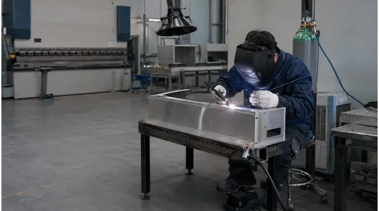
Why Aluminum Changes the TIG Welding Process?
Aluminum requires specific welding procedures due to its thermal properties, surface chemistry, and metallurgical response to heat. Understanding these material characteristics explains why specific machine settings, joint designs, and cleaning steps are strictly required.
Aluminum Oxide and AC Cleaning
Aluminum base metal melts at approximately 660°C (1200°F). However, the aluminum oxide layer that naturally forms on the surface melts at over 2000°C (3600°F). If this oxide layer is not managed, it acts as a thermal insulator and a physical barrier, preventing the weld puddle from forming and blocking root fusion.
To penetrate this barrier, manual aluminum TIG welding relies on Alternating Current (AC). The AC cycle constantly switches between two polarities:
- Electrode Negative (EN): Directs heat into the base material to create penetration.
- Electrode Positive (EP): Directs heat toward the tungsten, providing a cathodic cleaning action that breaks up the surface oxide.
This cathodic cleaning action leaves a visible frosted band along the edges of the weld bead. However, the electrical cleaning provided by the EP cycle cannot remove oil, grease, or heavy dirt. It is not a substitute for mechanical brushing and chemical degreasing prior to welding.
Heat Flow Through the Part
Aluminum has exceptionally high thermal conductivity, transferring heat away from the weld zone much faster than carbon steel or stainless steel.
When establishing the arc, a high initial amperage is required to overcome this rapid heat transfer and form a puddle. As welding progresses, the surrounding base material absorbs and retains this heat. If the heat input remains constant, the material approaches its melting point across a wider area, increasing the risk of sudden burn-through.
Heat accumulates even faster at corners, outside edges, and on smaller machined components. This physical reality makes dynamic heat control—typically managed via a foot pedal—critical, especially for thin sheet metal where heat saturation happens in seconds.
Alloy, Temper, and HAZ Strength
The heat from welding permanently alters the mechanical properties of the aluminum base metal in the heat-affected zone (HAZ). The extent of this strength loss depends heavily on the alloy series and its temper condition.
Non-heat-treatable alloys, such as 5052-H32, gain strength through strain hardening. The heat of the TIG arc removes this work-hardened state, returning the HAZ to an annealed condition. Heat-treatable alloys, such as the widely used 6061-T6, rely on specific thermal processing for their strength. Welding overages the material in the HAZ, resulting in a significant reduction in tensile and yield strength.
| Condition | Typical Tensile Strength (6061-T6) |
| Before welding | About 45 ksi |
| As welded | About 27 ksi |
(Note: These figures are typical reference values. They should not replace structural design minimums or formal welding procedure qualification records.)
💡 Manufacturing Reality Check: We frequently receive drawings specifying welded 6061-T6 parts with high structural load requirements. Often, the designer assumes the part retains its T6 strength across the joint. It does not. Designing your assembly based on the “as-welded” strength saves you from unexpected failures in the field.
Recovering this lost strength requires post-weld heat treatment (PWHT). However, applying artificial aging alone does not fully restore T6 properties. A complete heat treatment cycle—involving solution heat treating, quenching, and artificial aging—can cause severe dimensional distortion in welded assemblies.
Match the Aluminum TIG Setup to the Part
Machine parameters for aluminum TIG welding should be built around the specific joint geometry, material thickness, and production requirements, rather than relying on standard presets.
Amperage, AC Balance, and Frequency
Modern AC TIG inverters allow operators to manipulate the arc profile and heat distribution by independently adjusting amperage, balance, and frequency.
| Control | Main Effect | Excessive Setting |
| Amperage | Heat and puddle formation | Burn-through and wide HAZ |
| EN percentage | Penetration and travel speed | Insufficient oxide cleaning |
| EP percentage | Oxide cleaning | Tungsten overheating |
| AC frequency | Arc width and direction | Overly narrow or unstable setup |
The required amperage is heavily influenced by the joint type. An outside corner joint restricts heat flow and requires less amperage, while a T-joint draws heat away in three directions and requires significantly more power for the same material thickness.
Operators use AC Balance to adjust the ratio of EN to EP. A typical starting point for clean material is 70% to 75% EN, which provides adequate penetration while maintaining a sufficient cleaning band. AC Frequency (typically set between 80 Hz and 120 Hz) controls the cone shape of the arc. A higher frequency produces a tighter, more directional arc that works well for fillet welds, while a lower frequency provides a wider arc profile suitable for outside corner joints.
Tungsten, Gas, and Torch Setup
The equipment configuration must support the selected AC parameters and material thickness.
- Tungsten Selection: Pure tungsten (green) is often used with older transformer machines, but modern inverter machines perform better with zirconiated (white), lanthanated (blue/gold), or ceriated tungsten. The electrode diameter must be large enough to handle the maximum operating amperage.
- Tip Preparation: Inverter machines generally require a truncated or slightly blunted tip, unlike the fully balled tip used on older transformers. If the tungsten contacts the filler rod or the puddle, welding must stop immediately, and the electrode must be reground to prevent contamination.
- Shielding Gas: 100% Argon is the standard for most aluminum TIG applications. For base material exceeding 3/8″ (9.5mm) in thickness, an Argon/Helium mixture is sometimes used to increase the arc voltage and generate a hotter puddle. Gas flow rates scale with the cup size and joint configuration.
Cost implication for buyers: While 100% Argon is standard and cost-effective, specifying a Helium mix for thicker plates to achieve deeper penetration will noticeably increase the consumable cost of the project.
⚠️ Manufacturing Safety Considerations:
- Keep all exposed skin fully covered to prevent severe UV burns caused by the highly reflective aluminum arc.
- Use appropriate welding helmets and heat-resistant gloves.
- Ensure adequate local ventilation in the welding area.
- Never use chlorinated cleaning solvents (like brake cleaner) near welding operations, as the UV light can convert them into highly toxic phosgene gas. Ensure approved solvents (like acetone) have completely evaporated before striking an arc.
Filler Selection and Finish Compatibility
The filler metal determines the mechanical integrity, cracking resistance, and final appearance of the joint. ER4043 and ER5356 are the most common aluminum TIG filler rods, but they serve different engineering requirements.
| Requirement | ER4043 | ER5356 |
| Fluidity | Better | Lower |
| Crack resistance | Good for many 6xxx combinations | Depends on base alloy |
| Ductility and toughness | Lower | Higher |
| Fillet weld shear strength | Lower | Higher |
| Weld appearance | Usually brighter | May produce more smut |
| Anodized color match | Often turns dark gray | Usually closer to base metal |
| Elevated-temperature service | Often more suitable | May be restricted |
Beyond 4043 and 5356, specific applications require alternative alloys. ER4047 contains higher silicon, providing excellent fluidity and low shrinkage, which is often used for thin sections and leak-tight joints. ER4943 offers better shear strength than 4043 while maintaining similar crack resistance. ER4643 is often selected when the assembly will undergo post-weld heat treatment. It is also important to note that high-magnesium base alloys (like 5083) have strict filler limitations, and 5356 should not be used in environments operating above 65°C (150°F) due to the risk of stress corrosion cracking.
💡 A Common and Expensive Mistake:
If a welded assembly will undergo clear or color anodizing, ER4043 will turn a stark, dark gray due to its silicon content, ruining the cosmetic finish. If your part requires anodizing, you must specify ER5356 on your manufacturing drawings. Do not rely on ER5356 solely for anodizing compatibility if the structural requirements dictate a different filler.
Design and Prepare the Joint Before Welding
Engineering drawings often specify the final weld size but overlook the preparation required to achieve it. Poor fit-up and inadequate cleaning are the leading causes of weld failure and cost overruns in aluminum fabrication.
Cleaning and Contamination Control
Aluminum is unforgiving of surface contaminants. While the AC arc provides electrical cleaning to break up the oxide layer, it cannot remove hydrocarbons or moisture. These contaminants break down in the heat of the arc, trapping hydrogen gas in the puddle and causing internal porosity.
Common sources of shop contamination include stamping oils, CNC machining coolants, protective film adhesives, plasma cutting dross, moisture drawn from the air by improperly stored filler rods, and cross-contamination from tools used on carbon steel.
The sequence of cleaning is critical: you must degrease the part before brushing it. Using a wire brush on an oily surface simply drives the hydrocarbons deeper into the soft aluminum.
A reliable production cleaning sequence involves:
- Remove all oils, grease, and adhesives using an approved solvent (like acetone).
- Remove the aluminum oxide layer using a dedicated stainless steel wire brush.
- Wipe down the filler rod to remove storage contaminants.
- Weld the joint as quickly as possible after cleaning.
- Avoid touching the cleaned joint or filler rod with bare hands.
Hidden Cost Alert: A skipped degreasing step saves two minutes in prep time but often results in expensive weld cut-outs, rework, and scrapped parts later in the production cycle.
Joint Geometry and Torch Access
Joint design dictates how efficiently the welder can control the arc and apply filler metal. Different joints naturally demand different heat inputs: butt joints require moderate heat, outside corners require minimal heat, and T-joints demand high heat due to the three-way thermal draw. Tube-to-sheet joints require constant angle adjustments that slow down travel speed.
Engineers must also account for torch accessibility. The welder needs physical clearance to maintain a 10-to-15-degree push angle while simultaneously feeding the filler rod into the leading edge of the puddle.
Thick plates generally require grooved joints to ensure full penetration. However, the geometry must be carefully calculated. The issue is not the V-groove itself, but rather a groove that is too narrow, which prevents the TIG cup from reaching the root. This causes the arc to wander to the sidewalls, resulting in a lack of root fusion.
| Design Problem | Manufacturing Result |
| Deep, narrow groove | Poor torch and filler access |
| Large root gap | Burn-through and excess filler |
| Oversized weld | More labor, heat, and distortion |
| Hidden joint | Difficult welding and inspection |
| Long continuous weld | Higher cost and warpage |
Fit-Up, Fixtures, and Warpage
Aluminum’s high coefficient of thermal expansion means parts will move significantly during welding. Relying on tight weld tolerances without a strategy for distortion control will result in high scrap rates.
Loosening tolerances on non-critical dimensions helps, but it does not replace the need for proper joint design. Gaps in the fit-up require the welder to add more filler metal, which increases the total heat input and worsens the resulting distortion.
Heavy clamping is often used to hold parts in place, but fixtures cannot replace a logical welding sequence. Over-clamping locks in residual stress; when the clamps are released, the part will often spring out of tolerance. A better approach utilizes proper tack welding:
- Apply tack welds at calculated lengths and spacing.
- Use a symmetrical sequence to balance the pulling forces.
- Pre-set parts with a slight reverse angle to compensate for expected shrinkage.
- Use copper backing bars and aluminum blocks to draw heat out of the part quickly.
If a part requires precise final dimensions (such as sealing surfaces or tight assembly points), the most reliable manufacturing method is to design the welded assembly with machining allowances. The part is welded slightly oversized, allowed to cool, and then CNC machined or 5-axis milled to final tolerances using a stable datum point.
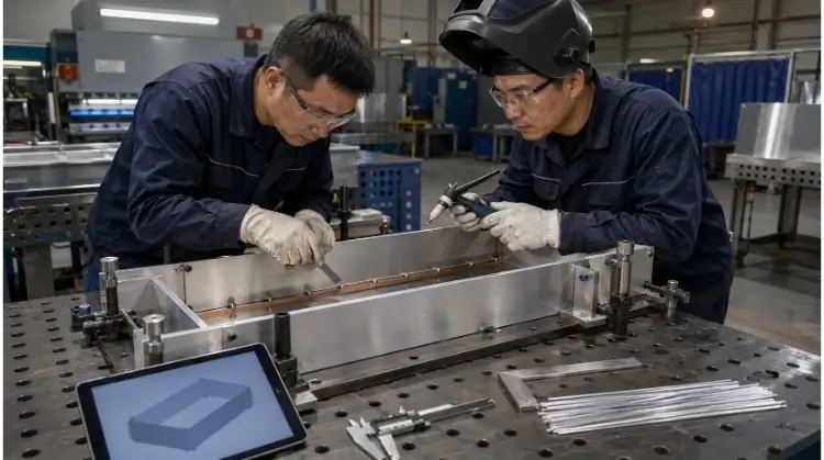
Control Heat and Defects During Welding
With the machine set and the joint prepared, the focus shifts to arc execution and thermal management. This phase dictates the internal integrity and dimensional accuracy of the final part.
Torch, Arc, and Filler Control
Manual TIG welding requires the operator to control the torch, the filler rod, and the foot pedal independently. The torch must maintain a tight, consistent arc length. If the arc is too long, the voltage increases, the heat spreads uncontrollably, and the shielding gas coverage is compromised.
The arc should be directed precisely at the root of the joint to ensure fusion before filler metal is added. Once the puddle forms rapidly, the filler is always dabbed into the leading edge of the molten puddle, never directly into the tungsten arc. The travel speed must be constantly adjusted based on the width of the puddle.
If the tungsten accidentally contacts the filler rod or the puddle, welding must stop immediately. The contaminated tungsten must be removed and reground; attempting to weld with a contaminated tip will cause arc wandering and introduce tungsten inclusions into the weld.
⚠️ Quality Standard: A stacked-dimes appearance does not prove full fusion, low porosity, or adequate joint strength. A weld can look cosmetically perfect on the surface while suffering from a complete lack of root fusion underneath.
Heat Input and Distortion
Because aluminum absorbs heat so quickly, a weld that starts smoothly can turn into a melted, sunken mess by the time the torch reaches the end of the joint. The welder must gradually back off the foot pedal (reducing amperage) as the overall temperature of the part rises. Heat input must be dropped even further when approaching edges or corners where heat has nowhere to escape.
To control distortion, engineers and fabricators must minimize unnecessary continuous welds and control the weld leg size.
Production Case Study: Sheet Metal Enclosure
- Material: 3mm (0.118″) 5052-H32 Aluminum.
- The Problem: A 600mm long outside corner joint was initially welded continuously from one end to the other. The concentrated, sustained heat input caused the sheet to bow inward by nearly 4mm, exceeding the assembly tolerance.
- The Solution: The manufacturing process was adjusted. The continuous weld was replaced with 50mm stitch welds. The sequence was staggered (welding section 1, then section 4, then section 2), allowing cooling time between passes, and a thick copper chill bar was clamped behind the joint.
- The Result: Total deflection was reduced to under 0.5mm, eliminating the need for post-weld manual straightening.
Defect Diagnosis and Correction
When defects occur, simply adjusting the AC Balance is rarely the complete solution. While balance controls oxide cleaning, it will not fix porosity caused by a draft blowing away the shielding gas or moisture trapped in the joint.
| Defect | Likely Causes | Corrective Direction |
| Porosity | Oil, moisture, gas leaks, or contaminated filler | Correct cleaning, storage, and gas delivery |
| Lack of fusion | Oxide, low root heat, long arc, or poor access | Improve preparation and arc placement |
| Burn-through | Wide gap, slow travel, or excessive heat | Improve fit-up and heat control |
| Crater cracking | Unfilled crater or sensitive alloy | Use downslope and fill the crater |
| Tungsten contamination | Contact with filler or puddle | Stop and regrind |
| Distortion | Long welds, excess heat, or poor sequence | Change weld size, order, and fixture |
Special attention must be paid to the start and end of the weld:
- At the start: Shielding gas pre-flow must be active before the arc strikes to purge the air, preventing initial oxidation and tungsten contamination.
- At the end: The welder cannot simply snap the arc off. The amperage must be tapered down gradually (downslope) while adding a final dab of filler to fill the crater. Leaving a concave crater at the end of a weld on crack-sensitive alloys (like 6061) will usually result in crater cracking. Post-flow gas must remain on until the puddle solidifies and the tungsten cools. For highly critical or pressurized parts, run-on and run-off tabs are often used so the start and stop points can be machined off entirely.
Move the Weld Into Repeatable Production
Transitioning an aluminum weldment from a rapid prototype to mass manufacturing shifts the focus from feasibility to repeatability and cost control. Procurement managers and engineers must align on process selection, strict acceptance criteria, and process lock-downs to avoid ballooning costs.
Process Selection and Cost
TIG welding is not always the most economical choice for production. Understanding when to switch processes is critical for controlling unit costs.
| Process | Best Fit | Main Cost Driver |
| TIG | Thin parts, short welds, and visible joints | Skilled labor and cycle time |
| MIG | Longer welds and larger batches | Setup and finishing |
| Pulsed MIG | Medium-to-high production | Equipment and parameter control |
| Laser | Tight-tolerance repeat production | Equipment and fit-up accuracy |
It is a common misconception to evaluate cost solely by comparing the arc travel speed of TIG versus MIG. Actual manufacturing cycle time depends heavily on the part geometry and the quality requirements.
For example, a MIG weld might be laid down much faster than a TIG weld, but if the drawing requires a perfectly smooth cosmetic finish, the extensive post-weld grinding required for the bulky MIG bead will make the total cycle time—and the final cost—significantly higher than if it were TIG welded from the start.
Beyond the welding process itself, unit cost is driven by:
- Total weld length: Replacing unnecessary continuous welds with stitch welds immediately cuts labor and heat distortion.
- Joint accessibility: Welds buried inside deep sheet metal channels or sharp inside corners require more time and increase the risk of defects.
- Fixturing time: How many times the part must be unclamped, rotated, and re-clamped.
- Post-weld processing: Grinding, polishing, or chemical etching required before anodizing.
- Inspection requirements: The ratio of parts requiring non-destructive testing (NDT) like leak testing or dye penetrant inspection.
Inspection and Acceptance
“Make the weld look nice” is the most dangerous note an engineer can put on a drawing. Visual appearance is subjective and cannot be quantified by a quality control department. A drawing must clearly define the functional requirements of the joint: structural strength, cosmetic appearance, hermetic sealing, or dimensional stability.
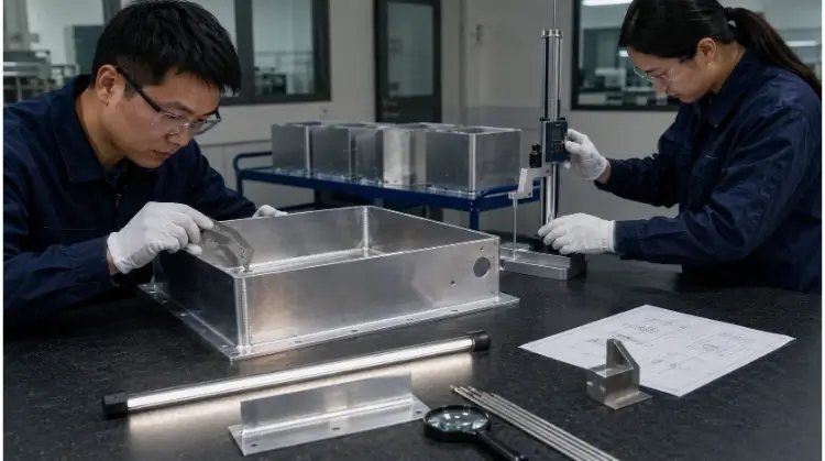
Different requirements dictate different inspection methods:
- Visual Testing (VT): Checks for surface porosity, undercut, and proper weld size based on defined standards. For aerospace, defense, or high-end industrial applications, ensure your manufacturing partner complies with structural aluminum welding codes like AWS D1.2 or ISO 3834.
- Dimensional Inspection: Verifies the part has not warped out of tolerance post-weld.
- Dye Penetrant (PT): Detects microscopic surface cracks or invisible pinhole porosity.
- Macro Etching: Cuts a cross-section of a sample part to verify root penetration and internal fusion.
- Pressure/Leak Testing: Immerses the part in water while pressurized with air to verify hermetic seals.
To ensure accurate pricing and eliminate disputes at receiving, manufacturing drawings must explicitly define:
- Exact weld locations, sizes (leg length), and whether they are continuous or intermittent.
- Specific zones where welds must be ground flush.
- Surface treatment requirements (e.g., “Must be suitable for Type II Clear Anodizing”).
- Maximum allowable distortion.
- The exact inspection method and sampling rate (e.g., “100% leak test at 50 PSI”).
Production Control and Traceability
During the prototyping phase, a highly skilled welder can manually compensate for poor fit-up or slight contamination. In batch production, relying on individual operator heroism leads to inconsistent quality and high scrap rates.
To achieve repeatability, the factory must lock down the manufacturing variables into a formal Welding Procedure Specification (WPS) or a standard operating procedure.
| Control Item | Required Record |
| Base material | Alloy, temper, and thickness |
| Filler metal | Alloy, diameter, and batch |
| Machine setup | Amperage, balance, and frequency |
| Joint setup | Gap, tack spacing, and fixture |
| Welding sequence | Start point and segment order |
| Inspection | Method, frequency, and acceptance |
Once the First Article Inspection (FAI) is approved, these variables cannot be changed. The cleaning method, the sequence of the stitch welds, the location of the copper heat sinks, and the strict limits on weld repairs must be standardized across the entire production run.
Unlike steel, aluminum rapidly degrades with repeated heat cycles. Excessive rework leads to grain growth and severe thermal cracking. Limiting rework attempts is critical to avoiding catastrophic failure in the field, which is why getting the process right the first time is non-negotiable.
Get a Free Engineering Review
Planning an aluminum welded assembly? Send us your CAD files and requirements. Before we generate a quote, our engineering team will provide a free Design for Manufacturability (DFM) review to optimize your joint design, reduce distortion risks, and eliminate hidden production costs.