Choosing between MIG and TIG welding is rarely just a welding decision. In real sheet metal production, it affects manufacturing cost, lead time, weld appearance, assembly stability, and even how much rework happens after welding.
MIG welding uses a continuous wire feed for speed and ease, making it ideal for thick materials and high-volume production. TIG welding employs a non-consumable tungsten electrode for ultimate precision and aesthetic control on thin, exotic metals. Choose MIG for efficiency and TIG for high-quality, intricate craftsmanship.
Ultimately, choosing between MIG and TIG is not a textbook physics decision. It is a strict engineering compromise balancing production throughput, cosmetic appearance, thermal control, and total unit cost.
MIG and TIG Solve Different Production Priorities
You cannot evaluate MIG and TIG in a vacuum. In a real-world manufacturing environment, these two processes serve entirely different strategic roles depending on your volume, material, and design intent.
Throughput and Deposition Rates
MIG (Metal Inert Gas) welding is built for speed. It uses a continuous, motor-driven wire feed that acts as both the electrode and the filler metal. This setup allows operators to lay down continuous weld seams with deposition rates that are typically two to four times faster than manual TIG.
Because of this sheer speed, MIG is the undisputed choice for heavy structural assemblies. When fabricating internal load-bearing frames or NEMA-rated electrical cabinets (typically 3mm and thicker), MIG keeps cycle times short and piece prices highly competitive.
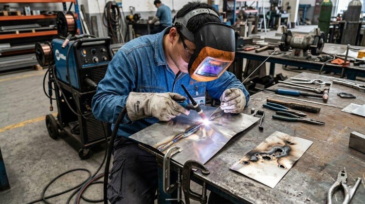
Precision Heat Control
TIG (Tungsten Inert Gas) welding operates on a completely different logic. It uses a non-consumable tungsten electrode to create the arc, while the operator manually feeds the filler rod.
This decoupling of the heat source from the filler material gives the operator absolute authority over the weld puddle. When welding miniature joints, or working near sensitive CNC-machined features that cannot tolerate thermal expansion, TIG provides the pinpoint heat control necessary to preserve the workpiece.
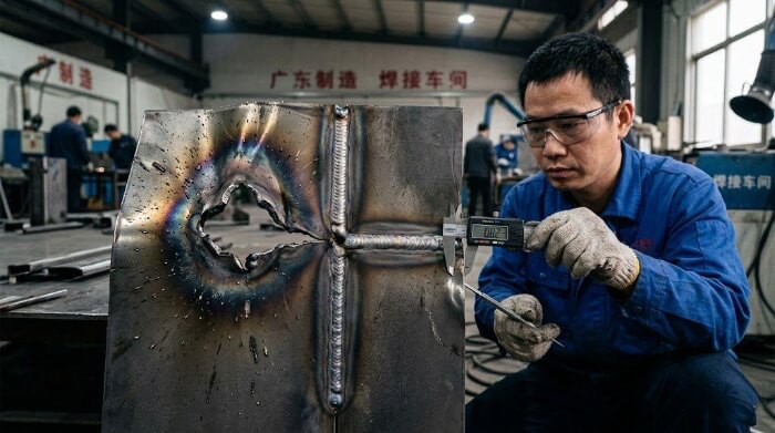
Visible Weld Quality and The Grinding Trap
When a part is forward-facing and aesthetic quality is non-negotiable, TIG is the industry standard. A skilled operator can produce a pristine, spatter-free “stack of dimes” weld profile that requires zero post-weld grinding.
MIG, conversely, generates micro-spatter and a raised weld bead. If a MIG-welded component—such as a front-facing medical device panel—requires a premium powder-coated finish, it will demand significant manual grinding to achieve a flush surface.
In many cases, the time saved on the MIG welding line is entirely lost in the grinding booth. For high-cosmetic parts, TIG’s slower, slag-free process often results in a lower total unit cost because it eliminates extensive post-processing labor.
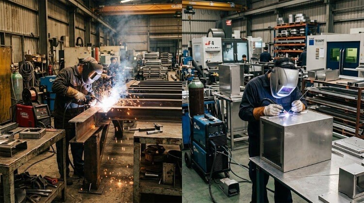
Production Scaling and Process Transitions
Experienced manufacturing teams rarely lock themselves into a single process for the entire lifecycle of a product. During the rapid prototyping phase, TIG is heavily utilized because it requires minimal tooling and allows for high-mix, low-volume flexibility.
However, as an order scales from 50 to 5,000 units, shops will actively redesign joints to transition from manual TIG to semi-automatic or Robotic MIG. In complex enclosures, it is common to use hybrid welding: running MIG on internal structural seams for mass production speed, and reserving TIG exclusively for visible exterior corners.
Thin Sheet Metal Requires Better Heat Stability
Welding thick steel plates is straightforward. Welding 1mm to 1.5mm sheet metal is where fabrication shops either prove their expertise or fail completely.
Burn-Through Risk on Thin Gauges
When an intense welding arc hits a thin edge, the metal reaches its melting point instantly. If the heat input is too high or the travel speed too slow, the arc will simply vaporize the base material, leaving a gaping hole.
TIG’s ability to initiate and maintain an arc at very low amperages makes it the safest process for thin-gauge components, such as 1.2mm 5052 aluminum electronics enclosures. It allows the operator to fuse the edges gently without blowing through the material.
Heat Distortion and Assembly Shift
Heat is the enemy of flatness. As a weld cools, the molten metal contracts, pulling the surrounding thin sheet metal with it. This thermal distortion (warping) is the leading cause of sheet metal rejection, especially in materials like 304 stainless steel.
A severely warped panel loses its dimensional accuracy, meaning the mounting holes will no longer align during final assembly. TIG’s concentrated, narrow heat-affected zone (HAZ) minimizes this stress, whereas the broad heat profile of standard MIG can easily twist a thin panel beyond repair.
Gap Tolerance and Fixturing Dependency
Thin sheet welding demands perfect fit-up. If upstream press brake bending is inaccurate and leaves a 1mm gap between two plates, welding becomes exponentially harder. The arc will bite into the exposed edges and melt them away rather than bridging the gap.
TIG is highly sensitive to this poor fit-up. To ensure repeatability, engineers must design self-locating joints (like tab-and-slot designs). Furthermore, moving into volume production requires the shop to invest in custom-machined welding fixtures to hold the parts perfectly tight before striking an arc.
Pulse MIG for Thin Sheet Scaling
While TIG is ideal for thin metal, it is often too slow and expensive for mass production. To bridge this gap, modern fabrication relies on Pulse MIG welding.
This technology rapidly pulses the welding current between a high peak (to melt the wire) and a low background current (to keep the arc stable). This allows a shop to achieve the fast deposition rates of MIG on 1.5mm aluminum or stainless steel, without the severe warping risks associated with traditional short-circuit MIG.
Material Type Changes Welding Stability
You cannot force the same welding parameters onto different metals and expect the same results. The thermal conductivity, melting point, and surface chemistry of the base material directly dictate which welding process will remain stable.
Carbon Steel and Stainless Steel Characteristics
Welding standard carbon steel (like Q235) is highly forgiving. MIG welding handles it effortlessly, providing deep penetration, fast travel speeds, and consistent bead profiles across high-volume batches.
Stainless steel (like 304 or 316) is a completely different story. It retains heat aggressively, making it highly susceptible to severe warping and rear-side oxidation (known as sugaring). For thin stainless enclosures, TIG is often mandatory.
Furthermore, achieving medical-grade or food-grade joints requires back-purging—flooding the inside of the part with argon gas to protect the rear of the weld. This effectively doubles your shielding gas consumption, a hidden material cost that must be factored into the quote.
Aluminum Welding and Oxide Removal
Aluminum is notoriously difficult to weld because of its chemistry. The surface is covered by a tough oxide layer that melts at around 2,000°C, while the underlying raw aluminum melts at just 660°C.
This is where AC TIG (Alternating Current) is non-negotiable for precision parts. The alternating current physically breaks up and cleans the oxide layer during the cycle, allowing the base metal to fuse cleanly.
While MIG can be used for thick aluminum structural frames, the soft aluminum wire frequently causes feeding jams. To run aluminum MIG reliably in production, the shop must invest in specialized push-pull gun systems.
Shielding Gas and Arc Physics
Shielding gas does more than just protect the molten puddle; it actively alters the physics of the arc.
For MIG welding steel, an Argon/CO2 mixture (like 75/25) is standard. The CO2 drives a deeper, hotter arc, while the Argon stabilizes the spatter. TIG, however, almost exclusively requires 100% pure Argon to maintain the pristine, highly focused arc necessary for cosmetic sheet metal work.
Arc Time vs. Total Cycle Time: The Hidden Cost of Grinding
Engineers often look at a quote and assume MIG is cheaper simply because the machine runs faster. But in professional fabrication, we calculate the Total Unit Cost.
Arc-On Time vs. Total Cycle Time
If you only measure “arc-on time,” MIG will always win. It lays down material rapidly and maximizes batch efficiency on the shop floor.
However, arc time is only one fraction of the manufacturing cycle. If a fast MIG weld requires complex pre-heating, or introduces severe thermal stress that requires post-weld mechanical straightening, the actual labor hours per part will skyrocket.
Weld Cleanup and The Grinding Trap
This is the most common hidden trap in sheet metal pricing. MIG welding inevitably creates micro-spatter and a raised, convex bead. If the component is scheduled for premium powder coating, that weld must be ground completely flush.
In high-cosmetic sheet metal fabrication, one minute of fast MIG welding can easily dictate three to five minutes of manual grinding.
The labor required for sanding and surface prep quickly overshadows the initial speed advantage. TIG’s clean, flush welds bypass this grinding bottleneck entirely.
Rework, Rejection, and Quality Risks
A cheap, fast weld is useless if it fails the final quality inspection. Excessive heat from an aggressive MIG pass can warp a chassis, making it impossible to align internal components during downstream assembly.
Fixing cosmetic defects, grinding out porosity, or mechanically straightening warped plates destroys production flow. Choosing a slower, more stable TIG process upfront often prevents costly customer returns and protects your delivery schedule.
Skilled Labor and Piece Price Scaling
TIG welding requires highly skilled, highly paid operators. Relying on manual TIG for high-volume orders creates a severe labor bottleneck, introduces human-error variations, and keeps the piece price artificially high.
For mass production, the engineering goal is almost always to transition to Robotic MIG. While this requires an upfront NRE (Non-Recurring Engineering) investment in custom welding fixtures, it amortizes quickly.
Automation eliminates the skilled labor bottleneck and guarantees that part number 5,000 is identical to part number 1, driving the long-term piece price down significantly.
Wrong Weld Selection Creates Production Problems
Specifying the wrong welding process on a manufacturing drawing does not just create a mess on the welding table; it creates a domino effect of failures across the entire production floor. When the process does not match the part’s design intent, the result is always increased scrap rates and blown budgets.
Cosmetic Weld Rejection and Ghost Lines
When aesthetic standards are high—such as in medical devices or consumer-facing electronics—a messy MIG weld is an instant quality control rejection.
Even if a shop spends hours grinding a MIG weld flat, aggressive grinding introduces deep abrasive marks. Furthermore, excessive heat can cause localized blackening or carbide precipitation in stainless steel. When the part is eventually clear-anodized or thinly painted, these “ghost lines” and heat tints will show right through the finish, ruining the product’s premium feel.
Excessive Distortion and The Sunk Cost Trap
Welding is typically one of the final steps in sheet metal fabrication. This makes it the most expensive place to make a mistake.
If you specify standard MIG on a 1.2mm aluminum chassis to save upfront costs, the broad heat-affected zone (HAZ) will violently warp the frame. When that part is scrapped due to thermal distortion, you are not just losing a bad weld. You are throwing away the expensive laser cutting, CNC press brake bending, and machining time that already went into that blank. TIG’s precise heat control protects your upstream manufacturing investments.
Porosity, Contamination, and Strength Loss
Choosing a fast MIG process without meticulous surface preparation—especially on aluminum—traps dirt, oils, and hydrogen inside the weld pool.
This creates porosity (internal pinholes) and severe weld contamination. While the weld might look acceptable on the surface, its internal cross-sectional strength is severely compromised. For load-bearing brackets or hermetically sealed enclosures, this hidden porosity leads to catastrophic mechanical failures in the field.
Delivery Delays and Supply Chain Bottlenecks
Every rejected weld means a part goes backward on the production line. Reworking a bad weld—grinding it out, cleaning the joint, and re-welding it—takes exponentially longer than welding it correctly the first time.
For the purchasing manager, this shop-floor inefficiency translates directly to missed shipping dates. A cheap welding quote that results in a 30% rework rate will ultimately bottleneck your entire supply chain and delay your time-to-market.
MIG vs TIG Welding Quick Comparison Table
Use this matrix during the Design for Manufacturing (DFM) phase to quickly evaluate which process aligns with your production priorities.
| Engineering Priority | MIG Welding (Metal Inert Gas) | TIG Welding (Tungsten Inert Gas) |
| Production Speed | Fast. Continuous wire feed enables high-volume throughput. | Slow. Manual filler feeding reduces output speed. |
| Heat Control | Broad HAZ. High risk of distortion on thin materials. | Pinpoint. Excellent thermal control via foot pedal. |
| Cosmetic Quality | Fair. Creates spatter; requires extensive manual grinding. | Premium. Slag-free “stack of dimes” appearance. |
| Rework Risk | High on thin sheets due to burn-through and warping. | Low, provided the upstream joint fit-up is perfect. |
| Automation Compatibility | High. Easily integrated into high-speed robotic cells. | Low. Difficult to automate; relies heavily on human touch. |
| Thin-Sheet Stability | Poor. (Unless using specialized Pulse MIG equipment). | Outstanding. Arc remains stable at extremely low amperages. |
| Skilled Labor Dependency | Moderate. Easier to train operators for repetitive tasks. | Extremely High. Requires years of specialized experience. |
| Overall Manufacturing Cost | Low raw cost, but high hidden costs in post-weld grinding. | High raw cost, but zero post-weld surface prep required. |
| Typical Applications | Heavy load-bearing brackets, internal structural frames, high-volume electrical cabinets. | Medical device panels, exposed aluminum enclosures, tight-tolerance precision components. |
Conclusion
There is no universally “superior” welding process in sheet metal fabrication. The right choice depends entirely on your material thickness, your cosmetic requirements, and where your product currently sits in its manufacturing lifecycle.
A seasoned fabrication partner will rarely force a single method. They will use TIG to perfect your early prototypes and guarantee cosmetic excellence. Then, as your order volume scales, they will redesign joints, build custom fixtures, and transition the heavy lifting to automated MIG cells to drive down your unit cost.
Ready to optimize your sheet metal production? Do not leave your manufacturing strategy to chance. At TZR, our engineering team brings over 10 years of sheet metal fabrication expertise to every project. Upload your CAD drawings today for a comprehensive DFM review.