
 English
  Spanish
  German
  Russian
  Italian
  French
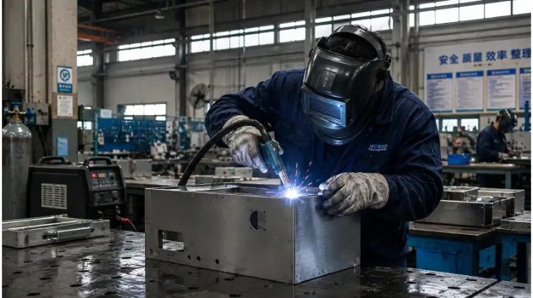
MIG welding is widely used for stainless steel fabrication because it offers a practical balance of production speed, process repeatability, and acceptable weld quality. However, successfully welding stainless steel requires significantly more precision than mild steel.
The primary challenge is not simply choosing the right wire spool. The real challenge lies in the material’s thermal properties. Stainless steel retains heat, expands significantly, and loses its critical anti-rust properties if exposed to prolonged high temperatures during the thermal cycle. Poor control over these variables directly impacts dimensional accuracy, drives up rework rates, and compromises the final corrosion resistance of the component.
This guide focuses on the production decisions that directly impact dimensional accuracy, rework rates, and the final corrosion resistance of the manufactured component.
Control the Heat Before It Controls the Part
Stainless steel’s thermal properties dictate the entire manufacturing approach. Failing to control the thermal cycle leads to immediate dimensional distortion and long-term corrosion failure.
Heat Input and Stainless Steel Corrosion Resistance
Stainless steel relies on a chromium oxide layer for corrosion resistance. Excessive heat input during welding compromises this passive layer.
When austenitic stainless steel remains in the 425°C to 815°C (800°F to 1500°F) temperature range for too long, carbon and chromium bond to form chromium carbides. This process, known as sensitization, depletes the chromium available at the grain boundaries, leaving the heat-affected zone (HAZ) susceptible to intergranular corrosion.
Heat tint on the weld surface is a direct symptom of the thermal cycle and oxidation level. While a light straw color is acceptable, dark blue or heavy black oxidation indicates excessive heat input and a high risk of localized corrosion drop-off.
The standard manufacturing control for this is utilizing low-carbon (“L” grade) base metals and filler wires, such as 304L or 316L. By capping the carbon content at 0.03%, “L” grades significantly reduce the material available for carbide precipitation.
Engineering Tip: Do not rely on a universal HAZ temperature limit. Focus on the thermal cycle: heat the joint sufficiently to achieve fusion, then allow it to cool rapidly.
Thermal Distortion in Stainless Sheet Metal
Austenitic stainless steels have a coefficient of thermal expansion approximately 50% higher than carbon steel, paired with only one-third of the thermal conductivity. Because the base metal cannot dissipate heat quickly, thermal stress concentrates locally around the weld joint.
In precision sheet metal fabrication—specifically gauges between 0.8 mm and 2.0 mm—this localized stress causes severe buckling, edge waviness, and an increased risk of burn-through.
Controlling distortion requires structural restraint and planned heat distribution:
- Tack Pitch: Place small, tight tack welds every 25 mm to 50 mm on thin sheet metal to lock joint alignment under heat stress.
- Heat Sinking: Clamp parts firmly against copper or aluminum backing bars. Copper pulls heat away from the HAZ far faster than the stainless steel can naturally dissipate it.
- Welding Sequence: Avoid continuous longitudinal passes. Implement a backstep or staggered intermittent (skip) welding sequence. This limits localized heat buildup and distributes thermal stress across the entire assembly.
Surface Preparation and Cross-Contamination
Contamination is a primary driver of high rework rates in stainless steel fabrication.
Before striking an arc, the joint must be degreased with acetone or a specific zero-residue solvent to remove cutting fluids and oils. Hydrocarbon residues introduce carbon into the weld pool, causing porosity.
Cross-contamination is an equally severe risk. If a wire brush, grinding disc, or file has previously touched carbon steel, it will embed microscopic iron particles into the stainless steel surface. These iron particles bypass the chromium oxide layer and will rust when exposed to moisture.
Quality Control Note: Iron contamination can cause immediate failure during post-weld salt spray testing. Multi-material workshops must strictly separate abrasives and brushes, clearly marking them “Stainless Steel Only.”
Build a Stable Stainless Steel MIG Setup
A stable arc and consistent material transfer depend on the correct configuration of filler wire, shielding gas, and the wire delivery system before production begins.
Match the Filler Wire to the Base Metal
Filler wire composition must closely match the base metal to maintain consistent mechanical properties and corrosion resistance across the welded joint.
| Base Metal | Common Filler Wire | Application Focus |
| 304 / 304L | ER308L | Standard austenitic fabrication. |
| 316 / 316L | ER316L | Marine, chemical, or high-corrosion environments. |
| Stainless + Carbon Steel | ER309L | Highly alloyed to account for carbon steel dilution. |
The “L” designation in the filler wire performs the same function as in the base metal: restricting carbon content to prevent sensitization.
It is important to note that ferritic, martensitic, or duplex stainless steels (e.g., 410, 430, 2205) cannot simply use standard 300-series wire. These materials require specific filler metals and often pre-heat or post-weld heat treatment procedures based on the final service environment.
Choose Shielding Gas for Arc Stability and Cost
Standard carbon steel shielding gas (such as 75% Argon / 25% CO₂) contains too much active gas for stainless steel, leading to heavy carbon pickup and severe oxidation.
Gas selection for stainless MIG requires balancing weld aesthetics, heat control, and cylinder costs:
- 98% Argon / 2% CO₂: A highly cost-effective and versatile mixture. The high argon content provides a stable arc, while the 2% CO₂ improves puddle fluidity without compromising the alloy’s carbon limits. This is standard for pulsed MIG applications.
- Tri-Mix (90% He / 7.5% Ar / 2.5% CO₂): The addition of helium increases arc energy and thermal conductivity, resulting in excellent wetting, flatter beads, and brighter finishes. However, helium is expensive. Tri-mix becomes cost-effective when the higher gas cost is offset by a reduction in post-weld grinding and polishing labor (e.g., in food-grade or medical equipment fabrication).
Operational Check: Maintain gas flow rates between 20 and 28 CFH (10–13 L/min). Flow rates above this threshold create venturi-induced turbulence, drawing ambient atmospheric air into the shielding envelope and causing subsurface porosity.
Stainless-Specific Wire Feeding and Gun Setup
Stainless steel wire is stiffer and harder than carbon steel wire, requiring specific modifications to the wire feeding system to ensure arc stability.
- Dedicated Liners: Use a dedicated Teflon (PTFE) or carbon-Teflon liner. This prevents iron cross-contamination from inside the cable (which occurs with standard steel liners) and reduces friction for smoother feeding.
- Drive Rolls: Standard V-groove rolls can slip on the harder wire. V-knurled drive rolls are generally recommended for reliable grip. Ensure tension is set correctly; over-tensioning knurled rolls will shave the wire, leading to clogged contact tips.
- Post-Flow Shielding: Utilize the post-flow setting on the power source. Keep the nozzle positioned over the end of the weld for 1.5 to 3 seconds after releasing the trigger. This protects the solidifying puddle from atmospheric contamination while it remains at elevated temperatures.
Set MIG Parameters Around the Actual Part
Parameter charts provide a baseline, but material grade alone does not determine the final welding settings. Production variables dictate the exact voltage, wire feed speed, and travel speed required to achieve a passing weld.
Start With Thickness, Joint and Welding Position
Process selection follows a strict sequence: Material → Thickness → Joint → Position → Wire → Gas → Transfer Mode.
A 2.0 mm flat butt joint with zero gap requires an entirely different setup than a 2.0 mm vertical-up fillet joint.
- Joint Type & Fit-up: Fillet joints typically require slightly higher heat input than butt joints of the same thickness to achieve root penetration. A wide joint gap changes the equation entirely, requiring lower heat and a manipulated torch technique to bridge the gap without burn-through.
- Welding Position: Flat and horizontal positions allow for higher deposition rates and hotter transfer modes (like spray transfer on thicker material). Vertical and overhead positions require lower heat input and faster-freezing puddles to prevent the molten metal from sagging.
Balance Voltage, Wire Feed Speed and Travel Speed
MIG welding relies on a balance between wire feed speed (WFS), voltage, and travel speed. When an operator observes a defect, adjusting the correct variable is critical.
- Arc sounds too harsh/crackling: Check voltage and arc length. The voltage may be too low for the current WFS.
- Weld appears cold, convex, or sits on top of the plate: Review WFS and voltage. Increase energy input or slightly reduce travel speed to allow the puddle to wet out.
- Burn-through occurs: Reduce the heat input per unit length. Increase travel speed, or decrease both WFS and voltage.
- Lack of fusion: Review energy input and joint preparation. Ensure the arc is directed at the root of the joint and the travel speed allows the puddle to dig into the base metal.
Starting Values (0.035″ / 0.9 mm ER308L Wire, 98% Ar / 2% CO₂):
| Thickness | Voltage | WFS (IPM) |
| 1.2 mm (18 ga) | 15–16 V | 160–180 |
| 2.0 mm (14 ga) | 16–17 V | 200–220 |
| 3.0 mm (11 ga) | 18–19 V | 260–280 |
(Note: These are baseline settings for flat position, short-circuit transfer. Always tune to the actual joint.)
Use Pulsed MIG for Better Heat and Puddle Control
For thin-gauge stainless steel and out-of-position welding, pulsed MIG (GMAW-P) is often the most cost-effective transfer mode. It significantly reduces average heat input while maintaining excellent fusion.
The power source rapidly alternates between a high peak current (which pinches off a single droplet of wire and propels it across the arc) and a low background current (which maintains the arc without transferring metal, allowing the puddle to cool briefly).
By adjusting the pulse frequency, operators achieve a “spray-like” transfer at average current levels much lower than traditional spray transfer.
Cost Control Note: By eliminating spatter and controlling weld reinforcement, pulsed MIG can reduce post-weld grinding time with flap discs by over 50%. For high-volume precision sheet metal orders, this is a critical process choice to lower the cost-per-part.
Adjust Inductance and Welding Technique
Because stainless steel has low thermal conductivity, the weld puddle is sluggish and viscous. This often results in a convex, highly crowned weld known as a “ropey bead.”
Inductance: If the power source allows for inductance adjustments, increasing the inductance slows the rate of current rise during the short-circuit phase. This increases the “arc-on” time, transferring more heat into the puddle and increasing its fluidity. The result is a flatter, smoother bead profile that requires less grinding.
Technique:
- Always use a push technique with a 10–15° travel angle. Pushing directs the shielding gas over the cooling weld pool and flattens the bead profile.
- Maintain a controlled, short stick-out (contact-tip-to-work distance).
- Avoid excessive weaving. Weaving significantly increases heat input and distortion risk; rely on a straight stringer bead whenever possible.
Diagnose Defects Before They Become Rework
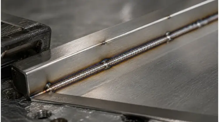
Visual inspection of the weld provides immediate feedback on process failures. Diagnosing defects on the floor prevents minor setup issues from escalating into high scrap rates.
Porosity, Spatter and Arc Instability
Porosity (Holes on or below the weld surface)
- Symptom: Small pinholes in the weld bead.
- Likely Cause: Atmospheric contamination due to poor shielding or base metal contamination.
- First Adjustment: Check gas flow rate (is it too high, causing turbulence, or too low?). Clean the joint of all oils/moisture.
- Application Impact: In the fabrication of cylindrical liquid tanks or pressure vessels, even subsurface porosity guarantees a failure during leak testing.
Spatter (Droplets fused to the base metal)
- Symptom: Excessive BB-like droplets requiring chipping or grinding.
- Likely Cause: Incorrect voltage/WFS balance, high CO₂ gas mixture, or low inductance.
- First Adjustment: Increase voltage slightly to smooth the transfer. Verify you are using an argon-rich gas mixture. Increase inductance if using short-circuit transfer.
Arc Instability
- Symptom: Arc stutters, pops, or wire burns back to the tip.
- Likely Cause: Poor wire feeding or worn consumables.
- First Adjustment: Replace a worn contact tip. Check for wire shavings in the liner. Verify stick-out is consistent and drive roll tension is appropriate.
Burn-Through, Distortion and Lack of Fusion
Burn-Through
- Symptom: The arc melts completely through the base metal, leaving a hole.
- Likely Cause: Excessive heat input per unit length.
- First Adjustment: Increase travel speed. If travel speed is already optimal, decrease WFS and voltage, or switch to a pulsed MIG process.
Distortion (Warping)
- Symptom: The assembly bends or pulls out of dimensional tolerance.
- Likely Cause: Unmanaged thermal stress from long continuous welds or poor clamping.
- First Adjustment: Break long welds into shorter segments. Implement intermittent (skip) welding sequences and increase the frequency of tack welds before final welding.
Lack of Fusion
- Symptom: Weld metal sits on top of the joint without penetrating the root or sidewalls.
- Likely Cause: Insufficient heat or excessive travel speed.
- First Adjustment: Increase WFS and voltage. Slow down travel speed to allow the arc to dig. Ensure the torch is directed at the leading edge of the puddle.
Ropey Bead, Undercut and Poor Weld Profile
Ropey Bead
- Symptom: Highly convex, narrow, and irregular weld bead.
- Likely Cause: Sluggish puddle due to low heat or low inductance.
- First Adjustment: Increase inductance to improve puddle wetting. Ensure voltage is adequate for the selected WFS.
Undercut
- Symptom: A groove melted into the base metal adjacent to the weld toe, unfilled by filler metal.
- Likely Cause: Voltage is too high, travel speed is too fast, or improper torch angle.
- First Adjustment: Decrease voltage. Adjust the gun angle to direct the arc slightly more toward the center of the joint rather than the edge.
Finish the Weld and Verify the Part
A stainless steel weld is not complete when the arc extinguishes. The post-weld surface treatment and inspection phases dictate whether the final component will actually survive its intended service environment.
Remove Heat Tint and Restore the Surface
Welding destroys the passive chromium oxide layer locally, leaving behind heat tint (oxidation) and a chromium-depleted zone. If left untreated, these areas will rust. Restoring the surface involves mechanical and chemical processes.
- Mechanical Cleaning: Stainless steel brushing, grinding, and polishing remove heavy slag, spatter, and severe heat tint. However, mechanical cleaning alone does not fully restore optimal corrosion resistance and can sometimes smear contaminants into the surface.
- Pickling: Pickling applies a strong acid solution (typically nitric and hydrofluoric acid) to actively dissolve the heat tint, the chromium-depleted layer beneath it, and any embedded iron contaminants.
- Passivation: Passivation is a distinct process. It uses a milder acid (nitric or citric) to strip away free iron from the surface and rapidly accelerate the reformation of a thick, uniform chromium oxide passive layer. Passivation does not remove heat tint or weld scale; the part must be clean or pickled first.
For critical components destined for food processing, medical devices, chemical handling, or marine environments, the passivation process should be verified and certified strictly against standard specifications such as ASTM A380 or ASTM A967 to guarantee long-term performance.
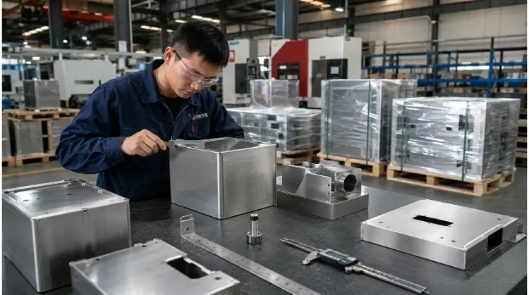
Inspect Weld Quality and Final Dimensions
Visual inspection is the first line of defense. Quality control should verify:
- Weld size and profile (avoiding excessive convexity)
- Absence of surface porosity, undercut, and cracking
- Acceptable levels of heat tint (based on AWS D1.6 or customer-specific standards)
- Final dimensional tolerances and distortion limits
Quality Control Note: A weld can look aesthetically perfect and still fail a functional requirement.
For critical applications, visual inspection must be supplemented with Non-Destructive Testing (NDT). Dye penetrant testing (PT) is highly effective for detecting microscopic surface cracks or lack of fusion, while leak testing is mandatory for any fluid-handling enclosures or pressure vessels.
MIG vs TIG and the Real Production Cost
Procurement teams often default to requesting TIG (GTAW) welding for stainless steel due to its reputation for flawless aesthetics. However, modern MIG processes—specifically pulsed MIG—fundamentally change the cost-benefit analysis for volume manufacturing.
| Requirement | MIG (GMAW) | TIG (GTAW) |
| Production Speed | Strong (Significantly faster) | Lower |
| Long Continuous Welds | Strong | Less efficient |
| Thin Precision Parts | Good (with Pulsed MIG setup) | Strong |
| Appearance Control | Good | Excellent |
| High-Volume Production | Strong | Usually slower |
| Heat Control | Good (with pulse) | Excellent |
When evaluating manufacturing methods, do not simply choose the “best looking” welding process. Choose the process that yields the lowest total production cost while maintaining controlled quality risks. The true cost of a weld is calculated as:
Total Cost = Welding Time + Rework + Grinding + Pickling + Distortion Correction + Inspection
For a run of 500 stainless steel electrical enclosures, the slight aesthetic advantage of TIG is often entirely negated by the sheer speed and reduced thermal distortion provided by a dialed-in pulsed MIG process.
⚠️ Safety Note: Stainless Steel Welding Fume Control
Welding stainless steel generates hazardous fumes, most notably Hexavalent Chromium [Cr(VI)], a known carcinogen.
- Do not rely solely on general shop ventilation. Use Local Exhaust Ventilation (LEV) positioned directly at the welding arc to capture fumes before they reach the operator’s breathing zone.
- Maintain and regularly inspect all fume extraction systems.
- Follow site-specific exposure assessments. Use appropriate respiratory protection (such as PAPR systems) when required by workplace risk assessments and applicable occupational health regulations.
Are you designing a stainless steel enclosure that requires tight tolerances, rapid prototyping, or controlled heat input? Send your 3D CAD files or prints to our engineering team for a rapid technical review and manufacturing quote.