Grinding Stainless Steel: Abrasives, Heat, and Surface Finish
Kevin Lee
Published:
To successfully grind stainless steel, operators must control heat to prevent warping and discoloration. Use INOX-rated ceramic or zirconia abrasives, apply consistent light pressure, and keep the grinder moving. Never use carbon steel tools on stainless steel to avoid iron contamination and rust.
Unlike mild steel, austenitic stainless steel traps heat at the point of friction. If an operator pushes too hard or uses the wrong abrasive, the metal will quickly suffer from heat tint, severe warping, and ruined corrosion resistance. Good results depend entirely on matching the right tool, abrasive, and finishing sequence to the part’s final requirement.
What follows isn’t textbook metallurgy—it is standard operating procedure on a professional shop floor. Here is what you need to know to lower your Total Cost of Ownership (TCO) and prevent rejected parts:
Core Principles for Grinding Stainless Steel:
Abrasive Selection: Use self-sharpening ceramic abrasives designed strictly for stainless steel (INOX).
Heat Management: Control heat through sharp abrasives, constant movement, and appropriate RPM—not operator muscle.
Strict Segregation: Physically separate stainless and carbon steel tools to eliminate cross-contamination.
Clear Specs: Define the final Ra (roughness) and grain direction before production begins to avoid cosmetic disputes.
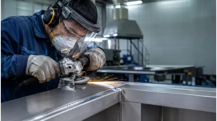
Controlled Sparks Along a Stainless Steel Weld
Why Stainless Steel Overheats, Smears, and Work-Hardens?
Understanding how stainless steel reacts to abrasive friction is necessary before selecting tools or setting process parameters.
Low Thermal Conductivity and Local Heat
Austenitic stainless steels conduct heat at a noticeably lower rate than standard carbon steels. When an abrasive wheel cuts into the metal, the generated heat does not dissipate quickly through the part. Instead, it concentrates at the contact zone.
This localized high temperature leads to heat tint (discoloration), warping, and surface damage. Thin sheets, tubing, and welded assemblies are particularly sensitive to this heat buildup. Furthermore, heat tint is not merely a cosmetic defect; it indicates a chromium-depleted layer that compromises the material’s corrosion resistance.
Grade, Hardness, and Work Hardening
Different stainless steel grades behave differently under an abrasive wheel.
Material Grade
Grinding Characteristics
Primary Risks
304, 316L
High toughness, prone to work hardening.
Rapid heat buildup, material smearing, abrasive loading.
430
Relatively easier to grind.
Deep scratches, iron contamination.
410, 420
Higher hardness after heat treatment.
Grinding burn.
440C
High hardness and wear resistance.
Micro-cracking, thermal damage.
17-4 PH
Strength and hardness depend on heat treat condition.
Dimensional changes, localized burning.
2205 (Duplex)
High strength, higher grinding resistance.
Excessive heat generation, rapid abrasive wear.
For grades like 304 and 316L, work hardening is a primary concern. It occurs due to localized plastic deformation and friction during the grinding process. If an operator continues to apply pressure using a dull abrasive, the wheel will rub rather than cut, rapidly hardening the surface and making subsequent material removal much more difficult.
Grinding Versus Finishing
It is helpful to separate the material removal process into distinct stages:
Grinding: Removing weld seams, heavy burrs, and excess base material.
Finishing: Removing the deep scratches left by grinding and blending the surface toward the target requirement.
Polishing: Further reducing surface roughness (Ra) or increasing reflectivity.
Deep scratches left by aggressive rough grinding directly increase the labor required in the finishing stage. Consequently, the stability of the upstream welding process dictates how much material needs to be removed. Whether a TIG weld should be ground flat depends entirely on the engineering drawing and cosmetic requirements; a joint should not be ground flush if doing so weakens the weld below structural requirements. Not all parts require a heavy rough-grinding step.
The cheapest grinding step is often the one avoided through better welding and joint fit-up.
Match the Tool and Abrasive to the Grinding Job
Selecting the correct abrasive structure, grain, and grit sequence minimizes heat input and reduces total processing time.
Grinding Wheels, Flap Discs, and Belts
Different tools distribute pressure and heat in different ways.
Tool Type
Primary Task
Advantages
Limitations
Grinding wheel
Heavy material removal
Fast cut rate, long life
Leaves deep scratches, high heat
Flap disc
Weld blending and edge work
Balances cutting and finishing
Easy to over-grind or gouge
Fiber disc
Fast stock removal on flat areas
High removal rate
Requires the correct backing pad
Abrasive belt
Long surfaces, restoring grain
Consistent scratch pattern
Requires specialized tools
Nonwoven wheel
Surface blending, light deburring
Low heat generation
Not suitable for stock removal
Tube belt system
Round tubes and curved surfaces
Large contact area prevents flats
Cannot access tight inside corners
When selecting wheels or flap discs, the shape matters. Type 27 (flat) works well for point contact at steeper angles (20°–30°). Type 28 (conical) is often used for wider welds at lower angles (around 5°). Type 29 (angled flap discs) provides a contoured profile for better surface contact. Note that while flap discs are versatile, round tubing is usually better served by wrap-around coated abrasive belt systems to maintain the radius.
Aluminum Oxide, Zirconia, and Ceramic
The abrasive grain dictates how the tool cuts and degrades over time.
Abrasive Grain
Cut Rate
Heat Generation
Tool Life
Typical Use
Aluminum oxide
Moderate
Higher
Shorter
General purpose grinding
Zirconia alumina
Higher
Moderate
Moderate
Heavy weld removal
Ceramic alumina
High
Lower
Longer
Continuous stainless processing
Nonwoven abrasive
Low
Lower
Moderate
Finish blending, cleaning
CBN
High precision
Depends on coolant
Long
Hardened precision components
Evaluating abrasives should be based on Total Cost of Ownership (TCO), not just the price per disc:
To accurately assess abrasive performance, manufacturing facilities should track the number of parts processed per disc, the cycle time per part, frequency of changeovers, and the rate of surface rework or scrap.
💡 Pro Tip for Procurement:
The most expensive abrasive on your shop floor is usually the cheapest one you bought. A standard aluminum oxide disc might cost less upfront, but if it glazes over quickly, your operator will spend 30% more time pushing on the tool, drastically increasing labor costs and the risk of heat distortion.
Grit Progression and INOX Markings
A controlled grit progression ensures that each step effectively removes the scratches left by the previous tool. P36 grit is suitable for heavy stock removal but leaves deep gouges. For sheet metal and cosmetic surfaces, starting with a P60 or P80 grit is usually safer.
Operators should not skip too many grit sizes in a sequence. The final grit size used is determined by the required Ra, grain direction, and the approved physical sample. Keep in mind that grit size does not directly equate to a specific Ra value.
Here are two common, generalized sequences:
Weld Blending
P60 or P80 → P120 → nonwoven blending
Finer Surface Preparation
P80 → P120 → P180 or P240 → final finishing medium
When purchasing consumables, buyers and engineers must verify the labeling. Abrasives used on stainless steel must be marked for “Stainless Steel” or “INOX” use. Procurement checks should include:
INOX marking indicating suitability.
Limits on Iron (Fe), Sulfur (S), and Chlorine (Cl)—typically < 0.1%.
Maximum RPM limits matching the power tool.
Applicable safety standards and expiration dates (for resin-bonded wheels).
🛡️ Audit Compliance Note:
During customer quality audits (especially for medical, marine, or food-grade components), simply buying INOX-rated abrasives is not enough. Auditors look for strict physical segregation: separate grinding bays, color-coded tools, and dedicated storage to guarantee zero carbon-steel cross-contamination.
Control Heat Before It Distorts the Part
Heat management is the defining metric of a successful stainless steel grinding operation. Because austenitic stainless steel traps heat at the point of friction, operators and CNC setups must actively manage how energy transfers into the workpiece.
Pressure, Speed, and Contact Pattern
Abrasive tools require a specific combination of speed and pressure to perform optimally. Applying sudden, heavy pressure does not speed up the job; it only generates excessive heat and glazes the abrasive wheel.
Operators should rely on auditory and tactile feedback. A significant drop in tool RPM or a change in the pitch of the motor usually indicates excessive pressure. The tool must remain in constant motion, overlapping previous grinding paths evenly. Dwelling on a single spot, even for a few seconds, concentrates thermal energy and risks metallurgical damage. Operators must also strictly observe the maximum rated RPM and the manufacturer’s recommended contact angle to prevent tool failure and erratic surface finishes.
💡 Shop-Floor Rule:
Let the abrasive do the cutting. More pressure does not automatically mean more removal.
Cooling and Abrasive Condition
For manual dry grinding, operators should use short, brisk strokes and alternate between different areas of the weld to give the metal time to cool. For precision wet grinding on dedicated machines, adequate coolant flow must be directed precisely into the contact zone, not just splashed onto the general area.
Abrasive condition directly impacts heat generation. When an abrasive disc loses its cutting ability, it must be replaced immediately. If a grinding wheel becomes loaded (clogged with metal) or out-of-round, it must be dressed. Operators should never attempt to compensate for a worn, dull abrasive by simply pushing harder.
A clean aluminum or copper backing plate can help absorb heat in some thin-sheet setups, but it must not distort or contaminate the part.
Thin Sheet, Tubes, and Welded Parts
Thin-gauge stainless steel is notoriously vulnerable to warping and burn-through. The residual stress left behind by welding compounds this problem, making the metal eager to distort as soon as grinding heat is applied.
Long weld seams on sheet metal should be ground in segments to distribute heat. The workpiece requires stable, clean support underneath to prevent vibration and flexing. When working on round tubing, operators should avoid rigid flat wheels that create localized flat spots; coated abrasive wrap-around belts distribute contact and preserve the tube’s true radius.
Narrow inside corners require specialized, small-diameter tools rather than forcing the edge of a large angle grinder into the joint. Finally, operators must confirm the allowable weld removal height specified on the engineering drawing before starting.
🚨 Cost Consequence:
Unlike mild steel, once a stainless steel sheet warps from localized grinding heat, it cannot simply be hammered back into tolerance. Attempting to mechanically force a warped assembly flat usually destroys the structural integrity and guarantees a rejected part at final QC. Heat control is scrap control.
🛡️ EHS Safety Note: Dust and Equipment
Always use correct guards and backing flanges. Never exceed the abrasive’s maximum RPM.
Implement local exhaust ventilation or source-capture dust collection at the workstation.
Control metal dust containing chromium and nickel. While not all grinding dust is Hexavalent Chromium (Cr(VI)), exposure assessments should dictate proper respiratory protection for operators.
Direct sparks away from combustible materials and routinely inspect dust collection systems to prevent fire hazards.
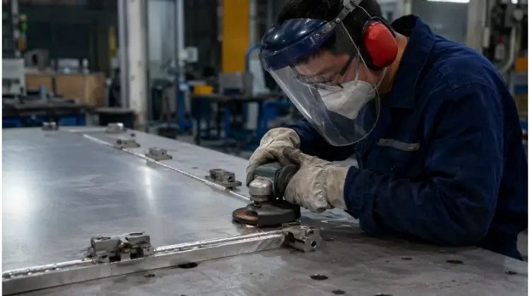
Thin Stainless Sheet Secured to an Aluminum Backing Plate
Diagnose Defects and Restore Corrosion Resistance
Grinding removes material, but it also alters the chemical state of the stainless steel surface. Identifying mechanical defects early prevents costly scrap, while proper chemical treatment restores the material’s essential corrosion resistance.
Heat Tint and Mechanical Defects
When visual or dimensional defects occur, production should stop until the root cause is identified.
Defect
Common Cause
Immediate Solution
Prevention Strategy
Blue/rainbow heat tint
Localized overheating.
Stop grinding; allow the part to cool.
Use sharper abrasives; shorten contact time.
Deep scratch marks
Grit is too coarse or skipped grits.
Return to the intermediate grit size.
Mandate a fixed grit progression standard.
Surface smearing
Abrasive is loaded or heavily worn.
Replace or dress the abrasive tool.
Track and limit abrasive lifespan.
Wheel stops cutting
Wheel is glazed or wrong spec used.
Dress the wheel or replace it.
Select the proper bond/structure for the grade.
Chatter marks
Unstable clamping or out-of-round wheel.
Halt machine; check part fixturing.
Balance and dress wheels; stiffen fixtures.
Flat spots on tubing
Tool contact area is too rigid/small.
Restore profile (if tolerances allow).
Use flexible wrap-around abrasive belts.
Erratic grain direction
Inconsistent operator movement.
Re-blend the affected area carefully.
Use directional templates or visual guides.
Sheet metal warping
Heat and stress concentration.
Check GD&T dimensions for scrap.
Segmented grinding paths; use heat sinks.
Iron Contamination and Tool Segregation
Cross-contamination is a silent killer in stainless steel fabrication. If a tool used on carbon steel touches stainless steel, microscopic iron particles embed themselves into the surface.
Facilities must strictly segregate abrasives, wire brushes, and polishing pads. Color-coding tools and establishing physically isolated storage areas are standard best practices. Workbenches, clamping fixtures, and material handling equipment (like forklift tines) must be kept clean. Furthermore, carbon steel grinding dust and sparks must be prevented from drifting onto stainless steel inventory. For highly critical 316L medical or marine projects, dedicated clean-room-style grinding bays are often required.
⚠️ The Delayed Cost of Contamination:
Embedded iron may not be visible during final inspection. The true cost of cross-contamination often doesn’t appear on the shop floor. Parts may pass visual QA, ship across the ocean, and arrive completely rusted due to humidity during transit—leading to 100% batch rejections and severely damaged supplier relationships.
Cleaning, Pickling, and Passivation
Finishing does not end when the grinder is turned off. The mechanical process must often be followed by chemical treatments, and the engineering drawing dictates which is required:
Pickling: Uses aggressive acids to strip away heavy oxide scales, heat tint, and the underlying chromium-depleted layer.
Passivation: Uses mild acids (nitric or citric) to dissolve embedded free iron and accelerate the formation of a robust, passive chromium-oxide layer.
Electropolishing: An electrochemical process that removes micro-peaks on the surface, lowering the Ra value and creating an ultra-clean, highly reflective finish.
Not every ground part requires passivation, but components destined for food processing, medical devices, marine environments, or chemical handling face stringent requirements.
It is a common misconception that a bright, shiny surface is fully protected. Passivation cannot fix deep scratches, correct dimensional errors, or polish the metal. Furthermore, a visually clean surface does not guarantee the absence of iron contamination. True corrosion resistance is not confirmed by a visual check; it must be executed and verified according to international standards like ASTM A380 or ASTM A967 (e.g., copper sulfate or high-humidity testing).
Define the Finish Before Production Starts
Many manufacturing disputes arise not from the grinding process itself, but from a poorly defined surface requirement. Vague drawing notes like “smooth finish” or “brushed appearance” leave the final acceptance entirely up to subjective interpretation, which inevitably leads to rejected parts and expensive rework.
Ra, Rz, and Grain Direction
A common engineering mistake is specifying an abrasive grit size (e.g., “Finish with 120 grit”) instead of a measurable surface roughness. Grit size is a process input; it does not guarantee a specific measurable output. Different abrasive brands, tool speeds, and operator pressures using the same grit will produce vastly different finishes.
Instead, define the surface using quantifiable metrics:
Ra (Average Roughness): The most common metric, measuring the average peaks and valleys of the surface.
Rz (Mean Roughness Depth): Often more useful for ground surfaces because it measures the extreme peak-to-valley heights, catching deep, rogue scratches that an Ra measurement might average out.
Grain Direction: For brushed or grained finishes, the drawing must specify the direction of the grain relative to the part geometry.
📝 Best-Practice Drawing Callout:
Surface finish: Ra ≤ 0.8 μm
Grain direction: Parallel to the long edge
Visual finish: Match approved physical sample
Requirements: No visible heat tint, cross scratches, or iron contamination.
Approved Samples and Inspection
For cosmetic parts, numbers alone are rarely enough. Before volume production begins, the manufacturer and the buyer should agree on a physical “limit sample” (a coupon of the same material and starting finish).
Both the supplier and the customer must retain identical master copies of this sample. Visual inspections should be conducted under standardized lighting, at a specific distance and viewing angle.
Furthermore, grinding removes material. First-Article Inspection (FAI) must verify that the part still meets all dimensional and GD&T tolerances after the weld removal and surface blending are complete. For critical components, surface roughness should be verified with a calibrated profilometer, and passivation records must be retained.
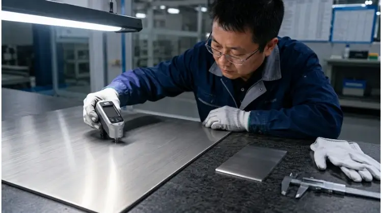
Brushed Stainless Surface Under Final Inspection
Cost Drivers and Supplier Questions
Procurement managers often wonder why grinding quotes vary so wildly. The true cost of grinding is dictated by labor time and consumable wear, which are driven by:
Over-specifying the finish: Requesting a near-mirror polish (Ra 0.2) on an internal structural component that nobody will ever see can increase your grinding costs by 300%. We always help customers match the finish spec to the actual functional requirement to avoid unnecessary costs.
Weld volume and accessibility: Grinding a heavy weld in a tight inside corner takes exponentially longer than blending a clean TIG weld on a flat surface. If a joint is too tight to reach with a grinder, our DFM (Design for Manufacturing) experts will suggest redesigning the bend or weld placement to save you manufacturing time.
Material grade and thickness: Harder alloys wear abrasives faster; thin sheets require slower, segmented grinding to prevent warping.
The delta between starting and final finish: Removing deep mill scale to achieve a polished finish requires multiple abrasive steps.
Passivation and testing requirements: Chemical treatments and certified reporting add processing time and overhead.
Conclusion
A stainless steel part can meet every dimensional requirement on the print and still be rejected because of heat tint, a single deep cross-scratch, uneven grain, or invisible iron contamination. These costly failures are easily prevented when the grinding method, allowable material removal, and finish standards are strictly defined before the first spark is thrown.
Kevin Lee has over a decade of experience in the sheet metal industry, specializing in precision fabrication and problem-solving. With a strong focus on quality and efficiency, he brings valuable insights and expertise to every project, ensuring top-notch results and customer satisfaction in all aspects of metalworking.

 English
  Spanish
  German
  Russian
  Italian
  French