
 English
  Spanish
  German
  Russian
  Italian
  French
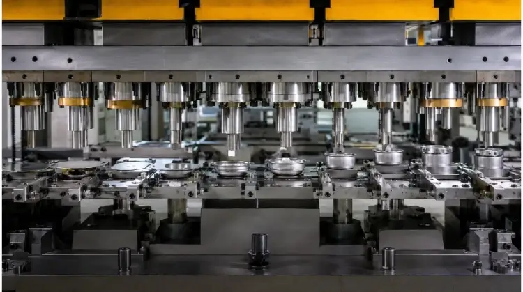
Transfer press stamping is a multi-stage metal forming process where blanks are separated from the strip and mechanically moved through individual die stations to create complex, deep-drawn parts. This allows the part to be redrawn, repositioned, pierced, trimmed, and formed without remaining attached to a carrier strip.
The added forming freedom can benefit large, deep-drawn, or multi-sided parts, such as EV battery housings, motor enclosures, and deep cylindrical pump bodies. However, the process only makes financial sense when part geometry, production volume, material use, and downstream operations justify the tooling and transfer system.
How Transfer Press Stamping Works?
Understanding this method requires looking inside the press. Let’s break down how raw metal transforms into a complex component across multiple synchronized tooling stations.
Blank Preparation
The process begins by supplying flat metal to the press. This is typically handled in one of three ways:
- Coil-fed blanking: A primary station inside the press cuts the blank directly from a continuous coil.
- Pre-cut blanks: Blanks are cut offline in a separate operation to optimize material nesting.
- Destacker feeding: A robotic or mechanical system feeds pre-cut blanks into the transfer press one by one.
Once the blank is separated from the strip, the material behaves differently during forming. Without a carrier strip, the part can be moved individually, rotated, and positioned for different tooling angles. The blank’s outline is optimized purely for material flow rather than strip continuity. However, this freedom is constrained by physical limits: the part must maintain specific gripping areas, and it must fit within the fixed transfer pitch (the exact distance between stations) of the press system.
Transfer Motion and Timing
Moving the unattached part safely between stations requires precise mechanical synchronization with the press slide. The motion follows a strict sequence:
Grip → Lift → Advance → Lower → Release → Return
The timing must be exact. As the die opens and the press slide moves upward, part lifters elevate the stamped component out of the lower die cavity. The transfer fingers move inward to secure the part, advance it horizontally to the next station, and lower it onto the station locators. The fingers must release and return to their home position before the press slide descends.
During the tool design phase, engineers must also carefully balance the tonnage distribution across these stations. If heavy drawing occurs on one end of the press and light piercing on the other, it can cause severe off-center loading, leading to premature die wear and press damage.
Station-by-Station Forming
To understand the progression, consider the forming of a deep-drawn metal shell. The part moves sequentially through specific operations:
- Blanking: Establishes the exact volume of material. If the blank is sized incorrectly, subsequent drawing stages will fail.
- First Draw: Pushes the flat blank into an initial cup shape. This must be a separate station because material can only stretch to a certain limit before tearing.
- Redraw: Deepens the cup while reducing its diameter. Gradual reduction prevents excessive wall thinning.
- Restrike: Compresses specific radii and sharpens features to control springback and stabilize dimensions.
- Piercing: Adds required holes. Piercing is done after drawing so that material flow does not distort the hole locations.
- Trimming: Removes the irregular excess material along the edges, which naturally occurs during deep drawing.
- Flanging: Bends the trimmed edge to its final assembly angle.
- Part Exit: The completed part is transferred out of the press into a chute or conveyor.
Depending on the design, transfer dies can selectively integrate operations like side piercing, tapping, coining, clinching, or fastener insertion. While this reduces downstream work, not all transfer dies yield a completely finished product; post-stamping machining or cleaning may still be required.
Transfer vs. Progressive Stamping: Choose by Part and Volume
Selecting the right stamping method requires comparing part geometry, material yield, and the total cost of manufacturing. Below is an objective comparison between transfer stamping, progressive stamping, and single-operation stamping.
Part Geometry and Draw Depth
| Project Condition | Transfer Stamping | Progressive Stamping | Single-Operation Stamping |
| Deep-drawn parts | Highly flexible | Restricted by carrier strip structure | Requires multiple manual transfers |
| Flat, high-speed parts | Usually offers no speed advantage | Usually the most suitable | Low efficiency |
| Multi-directional features | Easy to reposition the part | Constrained by carrier strip | Feasible but requires many operations |
| Large 3D parts | Highly suitable | Requires very wide material coils | Requires multiple separate dies |
| Design changes | High modification cost | High modification cost | Relatively easy to modify |
It is a misconception that progressive dies cannot perform drawing operations. However, because the part remains attached to the strip, the carrier restricts how the material flows into the die cavity. This limits the maximum draw depth and prevents the part from being reoriented between stations.
Material Yield
Material cost often dictates the process choice, especially for high-volume production or expensive alloys. In progressive stamping, the carrier strip is necessary to move the part, but it ultimately becomes scrap.
Transfer stamping eliminates the carrier strip. Engineers can calculate the exact blank size needed and utilize staggered nesting on the coil based entirely on part geometry. For high-cost materials like 300-series stainless steel, aluminum, or titanium, eliminating the carrier strip and optimizing blank nesting can often improve material yield by 10% to 25%.
Yield is measured using the following formula:
Material Utilization = Net Part Weight ÷ Gross Material Input × 100%
The actual percentage of material saved depends entirely on the part’s shape. A round blank might save significant edge material, while a square part might see a smaller difference in yield between the two processes.
Speed and Total Process Cost
When evaluating production speed, strokes per minute (SPM) is only one factor. Progressive dies frequently run at 60 to 150+ SPM, whereas transfer presses typically operate in the 15 to 50 SPM range due to the required transfer pitch and part stability during motion.
However, maximum SPM does not equal total process efficiency. The calculation for total process cost must include press cycle time, changeover time, secondary operations (punching, tapping, welding), part handling, work-in-process (WIP) storage, and repeated inspection cycles.
It is also crucial to account for setup times. Transfer dies require significantly longer changeover times than progressive dies due to the intricate calibration of transfer rails, fingers, and sensors. This is why smaller production runs cannot absorb the setup costs of a transfer press.
The core tradeoff: Progressive stamping may produce more strokes per minute, while transfer stamping may reduce the number of operations required after stamping.
Process Selection Matrix:
- For simple, high-speed, flat parts: Prioritize evaluating progressive dies.
- For deep-drawn, multi-directional forming: Prioritize evaluating transfer dies.
- For low production volumes or unfinalized designs: Prioritize evaluating single-stage dies, laser cutting, or CNC bending.
How to Design Parts for Reliable Transfer Stamping?
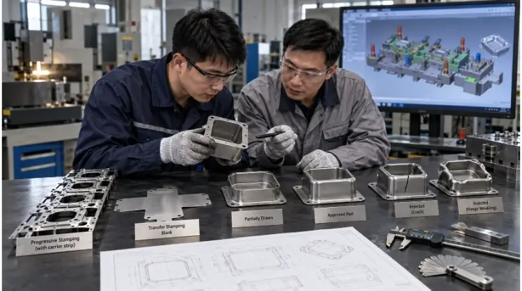
Successful stamping starts long before the press runs. Design choices directly dictate material behavior, tooling complexity, and overall manufacturing reliability.
Material and Blank Design
Material selection goes beyond simple grade specifications. Engineers must account for formability, ductility, work hardening rates, tensile strength, and springback. This is especially critical when stamping Advanced High-Strength Steels (AHSS) or titanium, where aggressive springback requires over-bending and restrike compensation built directly into the die. Grain direction, surface galling tendencies, and coil thickness variation will also dictate how the metal behaves under pressure.
The initial blank shape is equally critical. The blank’s perimeter dictates material flow, draw balance, final wall thickness, flange formation, and overall material yield.
Note: If an engineering guideline provides a maximum “draw ratio,” that number is not absolute. The actual achievable draw ratio depends heavily on the calculation method, material grade, starting thickness, lubrication, blank holder force, and tool surface conditions.
Radii and Feature Placement
The geometry of the part influences the number of required stations and the risk of manufacturing defects. Consider these engineering cause-and-effect relationships during the design phase:
- Radii: Sharp or excessively small radii increase local strain and the risk of cracking. As a general rule of thumb, draw radii should be at least 4 to 6 times the material thickness to prevent tearing, though this varies by alloy.
- Draw Depth: Excessive draw depths in a single hit will cause material failure. These designs require additional redraw stations to gradually form the shape.
- Wrinkling: If the design prevents adequate blank holder force during drawing, the material will wrinkle along the edges.
- Hole Placement: Piercing holes before forming is risky. If a hole is too close to a draw zone, the material flow will elongate and distort it.
- Flanges: Extremely narrow flanges are difficult to form and provide insufficient area for transfer fingers to grip.
- Feature Timing: Early piercing can reduce final positional accuracy due to material shifting. Critical features should be pierced after primary forming is complete.
- Restrike: Adding a restrike operation at the end of the sequence helps control springback and stabilizes the final profile.
Gripping, Datums, and Tolerances
Because the part is physically moved between stations, the geometry must provide reliable gripping areas, stable support surfaces, clear locating features, and adequate clearance for the transfer fingers.
Engineers must answer three practical questions when reviewing a design:
- Where will the transfer fingers grip the blank?
- As the part shape changes, can it still be gripped securely in the later stations?
- What feature will act as the locating datum for the next station?
For tolerances, avoid applying unnecessarily tight specifications across the entire part. Drawings should align with the actual locating datums used in the die. Functional dimensions can hold tight tolerances, but non-critical areas should be relaxed to account for springback and multi-station tolerance stack-up. Never rely on a generic tolerance table; final process capability must always be verified through tool tryout and physical measurement data.
What Drives Transfer Stamping Tooling and Part Costs?
Evaluating supplier quotes requires understanding specific fixed and variable cost drivers. Here is how tooling complexity and production variables shape your final part price.
Tooling and Tryout
The fixed investment for transfer stamping is substantial. It covers forming reviews, software simulation, blank development, station layout, and die manufacturing. It also includes designing the transfer fingers, integrating sensors and die protection, conducting tool tryouts, performing sample inspections, and making initial tool corrections.
Transfer dies often utilize independent stations or replaceable inserts, which benefits long-term maintenance. However, the transfer system itself increases debugging difficulty. Transfer fingers and locators are wear components that require calibration. If a single station jams, the entire line stops. Buyers should also note that late design changes may require modifying both the forming dies and the transfer tooling, doubling the engineering impact.
Unit Cost Drivers
To accurately compare manufacturing methods, break down the variable unit cost into its core components: raw material, press time, setup allocation, direct labor, scrap allowance, secondary operations, inspection, packaging, and routine maintenance.
Batch size is a critical variable. Because transfer dies can take several hours to set up and synchronize, running small batches (e.g., 5,000 parts) will severely inflate the “setup allocation” per part. Transfer stamping is most economical when run in large, continuous batches.
We recommend evaluating quotes using the following calculation:
Unit Cost at Volume N = (Fixed Program Cost ÷ N) + Material Cost + Press Cost + Secondary Cost + Quality Cost + Scrap Allowance
(Where: Fixed Program Cost = Tooling + Engineering + Tryout + Initial Corrections)
This formula provides a much clearer picture than simply dividing a blanket total cost by the production quantity, allowing buyers to see exactly where their capital is going.
Break-Even Calculation
When comparing transfer stamping against progressive stamping or single-die operations, calculate the break-even point using this formula:
Break-Even Volume = Difference in Fixed Cost ÷ Difference in Variable Cost per Part
To ensure the comparison is valid, both scenarios must use identical conditions: the same material and thickness, identical quality requirements, matching secondary operations, and the same assumed product lifecycle.
Example Project Comparison (Anonymized):
- Progressive Tooling: $45,000 (Higher material waste, requires secondary tapping offline).
- Transfer Tooling: $85,000 (Lower material waste, tapping integrated in-die).
- Variable Cost Savings (Transfer): $0.15 per part (saved on material and handling labor).
- Break-Even Volume: ($85,000 – $45,000) ÷ $0.15 = 266,666 parts.
- Conclusion: If the lifecycle volume exceeds 267,000 units, the more expensive transfer tooling becomes the financially superior choice.
Buyer’s Tip Box: Commercial Tooling Considerations
Before issuing a Purchase Order, clarify the following with your supplier:
- Tool ownership: Who holds the title to the die and the specific transfer fingers?
- Maintenance: Who bears the cost of routine maintenance and spare inserts?
- Modifications: How are engineering changes billed after the tool is approved?
- End-of-program: What happens to the tool and storage fees when production ends?
How to Reduce Defects and Downtime in Production?
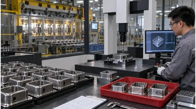
High-volume production is only profitable when it is consistent. Discover how to identify defects early, monitor in-die performance, and implement maintenance routines that prevent catastrophic downtime.
Transfer and Forming Defects
Even with perfect tool design, variations in material batches or normal tooling wear can introduce defects. Recognizing the root cause quickly minimizes scrap and gets the press back online.
| Defect | Likely Causes | Typical Actions |
| Cracking | Radii too small, insufficient material flow | Adjust corner radii, modify draw sequence, or improve lubrication |
| Wrinkling | Inadequate blank holder force, material flowing too fast | Adjust blank holder pressure (e.g., tuning nitrogen gas springs) or modify draw beads |
| Wall Thinning | High localized strain, insufficient draw stations | Modify blank shape or add redraw stations |
| Springback | High material yield strength, inadequate setting | Increase over-bending compensation or add a restrike station |
| Galling | Excessive friction, lubrication failure, tool surface wear | Improve lubrication, polish tool surfaces, or apply coatings |
| Misalignment | Transfer finger, locator, or timing errors | Re-calibrate gripping, locating datums, and press timing |
| Scrap Jam | Unstable scrap shedding paths | Inspect scrap size and clear shedding chutes |
In-Die Monitoring and Inspection
Running a transfer press blind is a massive financial risk. Modern transfer dies utilize in-die sensors to stop the press in milliseconds before a catastrophic tool crash occurs. Common systems include:
- Part-present sensors
- Double-blank detection
- Misfeed and transfer position monitoring
- Scrap detection
- Tonnage signature monitoring
It is crucial to understand that sensors primarily exist to protect the equipment and the die, not to measure part quality. For example, tonnage signature monitoring ensures that the forming force remains consistent throughout the entire stroke, instantly catching anomalies like dull punches or material hardness variations to prevent tool damage.
To ensure the parts meet print specifications, manufacturers rely on separate inspection methods. Vision systems can inspect predefined visible features at high speeds, while go/no-go gauges and Statistical Process Control (SPC) confirm that critical dimensions remain stable over the run. Advanced documentation, such as First Article Inspection (FAI), PPAP, and Cpk monitoring, should be established upfront based on specific customer or industry requirements.
Maintenance and Spare Tooling
Transfer dies have more moving parts than progressive dies, making preventative maintenance non-negotiable. A robust maintenance plan must cover cutting edges, forming inserts, transfer fingers, locators, lifters, sensors, lubrication systems, scrap chutes, and all replaceable wear components.
The goal of preventative maintenance is not simply fixing what is broken. It is a scheduled process designed to:
- Prevent gradual dimensional drift
- Reduce unplanned machine downtime
- Eliminate sudden die crashes
- Maintain stable delivery schedules
- Extend the overall lifecycle of the tooling
Buyer’s Supplier Checklist: Vetting a Transfer Stamping Partner
Before tool kickoff, ensure your supplier operates at the highest tier by asking these operational questions—standards we rigorously apply to our own facilities at Shengen:
- Have they successfully stamped similar materials and geometries?
- Does their press have the required tonnage, bed size, stroke, and energy rating?
- Does the press transfer stroke (pitch) accommodate your part’s required travel distance?
- Do they have in-house tool design and die repair capabilities?
- Is there a formalized tool tryout and part approval process?
- Can they provide FAI, PPAP, SPC, or Cpk data if required?
- Do they stock critical wear components (fingers, locators, inserts) in-house?
- Is there a documented history of routine die maintenance?
- Do they have backup press capacity or a contingency production plan?
Conclusion
Transfer stamping is not automatically better than progressive stamping. It becomes the stronger option when independent blank handling provides a clear advantage in forming freedom, material use, or downstream production cost.
The decision should be based on part geometry, material behavior, annual demand, tooling investment, secondary operations, and product lifecycle—not press speed alone.
Send us your 2D drawings, 3D models, material requirements, critical tolerances, and expected annual volume. Our engineering team at TZR can review the forming sequence, transfer method, tooling approach, and production risks before quotation.