
 English
 Spanish
 German
 Russian
 Italian
 French

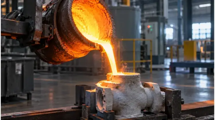
Stainless steel casting is a manufacturing process that pours molten stainless steel alloys into molds to produce complex, near-net-shape components. It is the most cost-effective method for creating durable, corrosion-resistant parts with intricate internal cavities that are too expensive for traditional CNC machining.
However, successfully procuring these castings requires more than just emailing a 3D CAD model to a foundry. The difference between a high-performing component and a costly pile of scrap lies in how you balance alloy chemistry, manage wall thickness to prevent internal shrinkage, and specify exact secondary machining allowances.
If you’re reviewing a CAD model or putting together an RFQ, you just need to know how to get the part made without defects or cost overruns. Here is exactly what matters on the shop floor: choosing the right alloy, tweaking your design to prevent shrinkage, and keeping hidden costs out of your quotes.
Quick Reference: Stainless Steel Casting Overview
- Main Processes: Investment casting (lost wax), sand casting, and centrifugal casting.
- Typical Parts: Valve bodies with internal channels, pump impellers, and structural brackets.
- Common Grades: CF8 (304), CF8M (316), CA6NM, and Duplex alloys.
- Specs to Define Early: Machining allowances, ISO 8062 dimensional tolerances, as-cast surface roughness (e.g., Ra 3.2 – 6.3 µm), and EN 10204 3.1 material certificates.
When to Choose Stainless Steel Casting
Evaluating whether a part should be cast comes down to geometry, material waste, and production volume. Casting is not a default replacement for machining; it becomes cost-effective when specific structural conditions are met.
Complex Internal Cavities and Irregular Geometries
Casting becomes viable when a part’s geometry makes CNC machining inefficient. For components like valve bodies with intersecting internal channels, curved pump impellers, or irregular fluid fittings, 5-axis machining often struggles with tool reach and turns over 60% of the raw billet into scrap. By forming the metal close to its final net shape, casting minimizes cutting time and significantly reduces raw material costs.
Part Consolidation to Eliminate Welding
Casting allows you to combine multiple machined parts and sheet metal brackets into a single, unified component. This eliminates weld seams, which are common weak points for fatigue and localized corrosion.
However, part consolidation requires evaluating the trade-offs: while you save on assembly steps and joint inspections, the single cast structure must undergo thorough initial performance validation to ensure it meets the load-bearing requirements of the original multi-part assembly.
Manufacturing Alternatives
Every manufacturing method has volume thresholds and physical limits. The decision between casting, direct machining, forging, or welding depends heavily on your order quantity and functional requirements.
| Manufacturing Method | Best Suited For | Volume & Cost Break-Even | Main Limitations |
| Investment Casting | Internal cavities, near-net shapes, complex curves. | Tooling breaks even around 300–500 units compared to 5-axis CNC. | Upfront tooling cost (aluminum dies); lower tensile strength than forgings. |
| CNC Machining | Tight tolerances (IT6-IT7), blocky/flat profiles. | Prototypes and low volumes (1–100 parts). | High material waste; highly expensive for deep cavities. |
| Forging | High-stress applications requiring directional strength. | High volumes (typically 5,000+ units) due to expensive steel dies. | Simple, solid geometries only; cannot form internal cavities. |
| Welded Fabrication | Large structural frames, simple enclosures. | Low-volume runs (1–50 units). | Weld seams introduce heat-affected zones (HAZ) and distortion risks. |
Pro Tip for Buyers: When evaluating casting against CNC machining, calculate the material removal rate. If your final part weighs 1 kg but requires a 4 kg raw block to machine, investment casting is usually the more cost-effective route for orders exceeding 300 units.
Compare the Main Stainless Steel Casting Processes
If casting is the right path, the next step is selecting the specific casting method. The choice dictates your upfront tooling costs, expected surface finish, and how much secondary machining will be required.
Investment Casting (Lost-Wax Process)
Investment casting uses an aluminum die to produce a wax pattern, which is then coated in a ceramic slurry. The wax is melted out (burned out), and molten stainless steel is poured into the resulting hollow ceramic shell.
This method reproduces fine details and typically achieves linear tolerances of ISO 8062 DCTG 5 to 7 with an as-cast surface roughness of Ra 3.2 – 6.3 µm. Part weight usually ranges from a few grams up to 50 kg (110 lbs). While it drastically reduces heavy milling, critical mounting faces, threads, and tight-tolerance bores will still require secondary CNC machining.
Limitation Check: Do not expect tight tolerances on small as-cast holes; holes under 5mm generally require post-drilling rather than casting.
Sand Casting
Sand casting forms the exterior mold from a sand and binder mixture, using sand cores to shape internal cavities. It is the practical choice for massive parts—such as heavy industrial pump housings or equipment bases exceeding 100 kg—where investment casting ceramic shells would crack under the metal’s weight. The upfront tooling (wood or polyurethane patterns) is faster and cheaper to produce than aluminum wax dies.
The trade-off is precision. Sand casting typically yields wider tolerances around ISO 8062 DCTG 10 to 12 and a rougher surface finish of Ra 12.5 – 25 µm. These parts require larger machining allowances and more aggressive post-machining to meet assembly requirements.
Pro Tip for Engineers: If your part size allows for either process, compare the total delivered cost. Sand casting tooling is cheaper, but the heavy secondary machining required to fix the Ra 12.5 surface and wide tolerances often makes the final part more expensive for medium-volume runs.
Centrifugal Casting
Molten stainless steel is poured into a spinning metallic or graphite die. The centrifugal force pushes the dense liquid metal against the walls while lighter oxides float to the inner diameter. This process is strictly for symmetrical, hollow cylindrical shapes like pipes, heavy-wall tubes, and ring components. After casting, both the inner and outer diameters are typically machined to remove surface impurities and hit final dimensions.
Choose Stainless Steel Grades for Your Application
Selecting the right material is not about picking a grade based on an industry nickname (e.g., “marine grade”). It requires matching the alloy’s chemistry directly to the part’s operating environment, mechanical loads, and downstream processing.
Corrosion Resistance: CF8 vs. CF8M
For general industrial applications handling fresh water or mild chemicals, CF8 (the cast equivalent of 304) provides sufficient corrosion resistance. However, if the part is exposed to chlorides (saltwater, de-icing salts) or specific chemical processing fluids, you need CF8M (the cast equivalent of 316). The addition of 2-3% Molybdenum in CF8M prevents pitting and crevice corrosion, especially in areas where stagnant fluids might accumulate in the casting’s geometry.
Welding Requirements: The Low-Carbon Option
If your cast component will be welded to a piping system or requires structural weld repairs, standard CF8 or CF8M poses a risk. The heat from welding causes carbon to react with chromium, forming chromium carbides at the grain boundaries—a process called sensitization. This leaves the weld area highly vulnerable to intergranular corrosion.
To prevent this, specify CF3 or CF3M. The “3” indicates a restricted carbon content (maximum 0.03%), which keeps the chromium intact during welding. Always state your welding intentions clearly in the RFQ so the foundry selects the correct low-carbon variant.
Strength and Toughness
When standard 300-series cast alloys lack the mechanical strength for high-pressure valves or turbine runners, shift to martensitic or duplex grades:
- CA6NM: A martensitic stainless steel offering high yield strength, excellent toughness, and good weldability. It is standard for hydroelectric pump and compressor components.
- Duplex Alloys (e.g., CD4MCuN): These offer a mixed austenitic-ferritic structure, delivering double the yield strength of CF8M (approx. 450 MPa vs. 205 MPa) and superior resistance to stress-corrosion cracking (SCC).
- Precipitation Hardening (e.g., CB7Cu-1 / 17-4 PH): Used when extreme hardness and wear resistance are required, typically delivered in specific heat-treated conditions (like H900 or H1150).
| Cast Grade (ASTM) | Wrought Reference | Primary Use Case | Key Limitation | Typical Delivery Condition |
| CF8 | 304 | General fluid handling, food processing equipment. | Vulnerable to chlorides and pitting. | Solution Annealed |
| CF8M | 316 | Marine, chemical processing, valve bodies. | Higher material cost due to Molybdenum. | Solution Annealed |
| CF3M | 316L | Components requiring structural welding. | Lower yield strength than CF8M. | Solution Annealed |
| CA6NM | 410 (Modified) | High-pressure pumps, hydro turbines. | Lower general corrosion resistance than 300-series. | Normalized & Tempered |
| CD4MCuN | 1A (Duplex) | Agitators, marine shafts, acidic chemical pumps. | Difficult to machine; requires rigid tooling. | Solution Annealed |
Pro Tip for Buyers: Wrought names (304, 316) and cast names (CF8, CF8M) have slightly different chemical compositions to optimize metal flow. If you put “Material: 316” on a casting drawing, a strict QA process will flag it. Specify “ASTM A351 CF8M” to avoid RFQ delays.
Design Parts to Reduce Casting Defects
A design that works perfectly for CNC machining will often fail in the foundry. Liquid metal shrinks as it cools, and uneven cooling causes internal voids (shrinkage porosity) or hot tears. Review your CAD models against these DFM (Design for Manufacturability) rules before requesting a quote.
Wall Thickness and Draft Angles
Do not apply a single “minimum wall thickness” rule to an entire part. A 2mm wall might cast perfectly on a 10mm flange but will fail to fill (misrun) on a 150mm long housing.
More importantly, assess how thickness changes. Transitioning abruptly from a 15mm thick mounting pad to a 3mm wall creates a temperature differential. The thin wall freezes first, cutting off the supply of liquid metal to the thick section, resulting in internal shrinkage voids. Always use a gradual taper (minimum 15-degree angle) between heavy and light sections.
Additionally, models designed for machining often have perfectly vertical walls. In casting, you must add a Draft Angle—typically 0.5° to 1° for investment casting and 1.5° to 3° for sand casting. Without this taper, the wax or sand pattern cannot be pulled from the tooling without tearing.
Fillets and Hot Spots
Sharp internal corners cause stress concentration and cooling cracks. A missing internal fillet doesn’t just cause a stress riser; it can increase the foundry’s scrap rate from hot tears by 15-20%, a cost that ultimately gets baked into your piece price. Add a minimum radius of 2mm to 3mm to all internal corners to guide metal flow.
Watch out for “hot spots” where multiple walls or ribs intersect (e.g., an X-shaped rib junction). The concentrated mass stays hot longer than the surrounding areas, inevitably causing a void. Offset or stagger intersecting ribs to distribute the mass evenly.
Cores and Openings
Internal cavities are formed using ceramic or sand cores. After the metal cools, this core material must be blasted or chemically leached out.
Avoid deep, “blind” holes or complex internal passageways with only one small exit. If the foundry cannot physically reach inside to remove the core material, the part is useless. Where possible, design through-holes, or add temporary cleanout ports that can be plugged after casting. Furthermore, ensure internal cores are supported at two or more points in the mold to prevent them from shifting under the pressure of the incoming liquid metal.
Specify Casting Tolerances and Machining Requirements
A casting is rarely a finished product. To successfully transition from a rough casting to a final assembled component, your 2D drawing must clearly separate as-cast surfaces from machined surfaces.
As-Cast Tolerances
Define the allowable dimensional variation for the raw casting using an international standard like ISO 8062 (e.g., ISO 8062-3 DCTG 5). However, understand that standard tables are general guidelines. Actual capability depends on part geometry, parting lines, and the foundry’s specific process controls. Never apply a tight tolerance block to the entire drawing. Specify strict tolerances only on the features that matter, and leave non-critical surfaces loose to reduce rejection rates and unnecessary cost.
Machining Allowance (Required Machining Allowance – RMA)
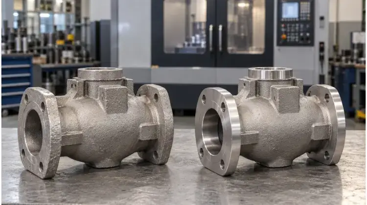
For surfaces that require secondary CNC operations—such as sealing faces, bearing bores, and threaded holes—you must add extra material to the cast model.
If you provide too little allowance, the CNC cutter will “skim” the surface and leave unmachined, rough cast patches. For stainless steel investment castings, specify a machining allowance of 1.5mm to 2.0mm on functional faces. For larger sand castings, this needs to increase to 3.0mm to 5.0mm.
Datums and Fits for Machining
The CNC machinist needs stable, repeatable points to grip the casting. If you select a curved, unmachined surface with a high draft angle as your primary datum, the part will sit differently in the CNC fixture every time, destroying your final tolerances.
Instead of using an entire cast surface as a datum, use Datum Targets (or the Reference Point System – RPS). Designate three specific, raised 10mm flat pads on the casting specifically for the CNC fixture to clamp onto. You can machine these pads off later if needed. Ensure the cutting tool has clear access to the machining faces without the cast geometry interfering with the spindle.
Pro Tip for Engineers: State explicitly on your drawing whether the draft angle is added to or subtracted from the nominal dimensions. This prevents nasty surprises when the casting arrives slightly thicker or thinner than the CAD model intended.
Select Heat Treatment and Surface Finishing
Getting the metal into the shape of your part is only half the battle. Post-casting thermal and surface treatments are required to unlock the actual mechanical properties and corrosion resistance of the stainless steel.
Heat Treatment
Cast stainless steel does not leave the mold ready for service. The uneven cooling process leaves internal residual stresses and segregates alloying elements.
For austenitic grades (like CF8M), Solution Annealing is mandatory. The casting is heated to dissolve chromium carbides back into the matrix, then rapidly quenched to lock them in place, restoring the alloy’s corrosion resistance. For martensitic grades (like CA6NM), Normalizing and Tempering are used to achieve the targeted yield strength and toughness.
Because heat treatment causes dimensional movement, always sequence it before final CNC machining. Machining first and heat treating second will warp your tight tolerances out of spec.
Cleaning and Passivation
Do not confuse cleaning with passivation. After cooling, the ceramic shell is knocked out, and the part is shot-blasted to remove the casting scale.
Ensure your foundry uses dedicated stainless steel or ceramic media for blasting. If they use the same steel shot for both carbon steel and stainless steel parts, they will embed carbon iron directly into your castings, guaranteeing aggressive rust in the field.
To prevent this and remove any machining contaminants, specify Passivation (per ASTM A967 or A380). This chemical bath strips away surface iron and accelerates the formation of a passive chromium-oxide layer, which is the actual source of stainless steel’s rust resistance.
Roughness and Appearance
Never use subjective terms like “smooth” or “bright” on an engineering drawing. Separate functional roughness requirements from cosmetic appearance.
For sealing faces or bearing journals, specify a quantitative value (e.g., Ra 1.6 µm) and designate them for secondary CNC milling or turning. For non-functional cosmetic surfaces, specify a mechanical finish like Glass Bead Blasting for a uniform satin matte look, or Electropolishing for a sanitary finish (bringing the surface down to Ra 0.4 µm or better). Keep in mind that blasting and polishing tools operate in a line-of-sight; deep, curved internal cavities cannot be effectively polished.
Define Inspection and Acceptance Requirements Before Production
Defining your inspection requirements at the RFQ stage ensures the foundry bakes the cost of quality control into their quote, rather than arguing over rejected parts after production.
Material Traceability
You need proof that the metal poured matches your specification. The foundry tracks this via a “Heat Number”—a unique identifier for a single furnace batch of molten steel.
Mandate an EN 10204 3.1 Material Certificate in your PO. This document provides the actual chemical composition (from a spectrometer reading taken before pouring) and the mechanical properties (yield, tensile, elongation) of the test bar poured from that exact heat, signed by the foundry’s QA representative.
Defect Detection (NDT)
Match the Non-Destructive Testing (NDT) method to your part’s risk profile:
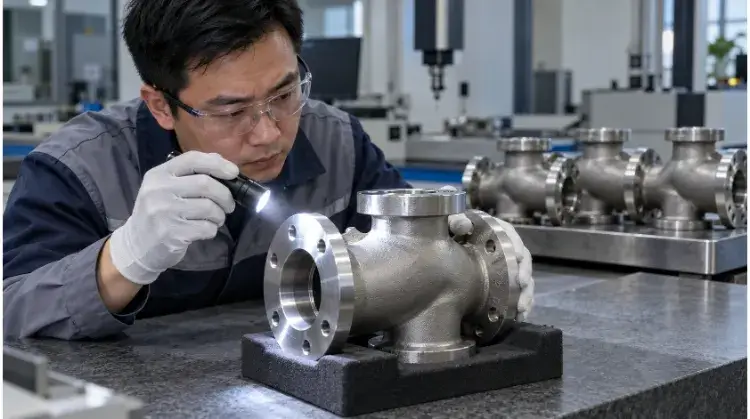
- Surface Defects: Specify Dye Penetrant Testing (PT) to reveal hairline cracks invisible to the naked eye.
- Internal Defects: Specify Radiographic Testing (RT / X-Ray) or Ultrasonic Testing (UT) for shrinkage voids.
- Leakage: For valve bodies and pump housings, specify Hydrostatic Pressure Testing to check for weeping through micro-porosity.
Cost Control Tip: Do not blindly specify 100% X-Ray for the entire batch unless it is a critical aerospace or high-pressure vessel part. RT is expensive. Mandate 100% X-Ray on the First Article Inspection (FAI) samples to validate the gating design, and then reduce to a 10% to 20% sample rate for mass production to balance risk and cost.
Acceptance Criteria
Your workflow should center around the First Article Inspection (FAI). The foundry produces a small sample batch for full dimensional layout, visual check, and material testing. Mass production cannot begin until you sign off on the FAI report. Define your Acceptable Quality Limit (AQL) for the production run and state explicitly whether weld repair is permitted for minor defects, and what re-inspection is required if repairs occur.
| Inspection Item | Location/Scope | Method | Acceptance Standard | Required Record |
| Chemistry & Mechanicals | Per Heat (Furnace Batch) | Spectrometer / Tensile Pull | ASTM A351 (or relevant spec) | EN 10204 3.1 Certificate |
| Surface Integrity | Critical radii / Welded areas | Dye Penetrant (PT) | ASTM E165 | PT Report (Pass/Fail) |
| Internal Soundness | Heavy sections / Intersections | X-Ray (RT) | ASTM E446 (Severity Level) | RT Films / Digital Report |
| Dimensional Limits | Machined Datums & Bores | CMM (Coordinate Measuring) | 2D Drawing Tolerances | FAI Dimensional Report |
Understand Stainless Steel Casting Costs and Lead Times
Comparing quotes requires looking past the raw unit price. A cheaper casting that requires heavy CNC rework will destroy your project budget.
Tooling and Samples
Tooling (wax injection dies or sand matchplates) is an upfront Non-Recurring Engineering (NRE) cost. Before issuing a PO, clarify the terms of ownership and maintenance. Generally, the buyer owns the tool, but the foundry stores and maintains it. Ensure the foundry’s quote includes a “Life of Program” maintenance guarantee, meaning they will repair or replace the tooling at their cost when it wears out.
Total Part Cost
When you receive a quote for a finished component, the cost structure roughly breaks down into the raw casting (30-40%), secondary machining (30-40%), and treatments/QA (20-30%). Two major factors dictate this price:
- Yield Rate: If a complex geometry drops the foundry’s casting success rate to 70%, the cost of the 30% scrapped parts is divided up and added to the price of the good ones.
- CNC Setup Penalty: While tooling is a one-time cost, CNC setup time is a recurring penalty on small batches. Setting up a 5-axis mill with custom fixtures takes 4 to 6 hours. If you order 50 parts, that setup time adds significant cost to each unit. If you order 500 parts, that setup penalty effectively disappears.
Development and Production
Plan your procurement schedule around realistic industrial lead times. For a new casting project, expect 4 to 6 weeks from drawing approval to the delivery of FAI samples. Once you approve the FAI, mass production typically takes another 4 to 6 weeks, depending on CNC and heat treatment schedules. Repeat orders skip the tooling phase, dropping the lead time directly to the 4-6 week production window.
Submit your 3D models, order quantities, and operating environment details to TZR. Our engineering team will evaluate your manufacturing route, identify machining reductions, and provide a clear, itemized quote.