
 English
  Spanish
  German
  Russian
  Italian
  French
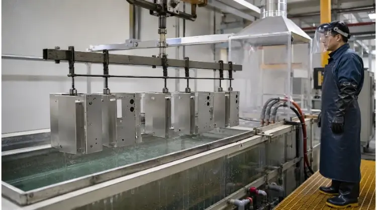
Electropolishing is an electrochemical finishing process that removes a thin, controlled layer of metal from a part’s surface. Often called reverse electroplating, it selectively dissolves microscopic high points to reduce surface roughness, remove micro-burrs, and improve corrosion resistance on alloys like stainless steel.
However, because it removes material, it directly impacts precision tolerances and can expose underlying manufacturing defects. This guide explains how to design for material removal, set realistic surface finish expectations, and establish objective inspection criteria before moving to production.
Electropolishing at a Glance
| Engineering Question | Short Answer |
| Does it add a coating? | No, it removes metal |
| Does it improve surface roughness? | Yes, within process limits |
| Does it remove deep scratches? | No |
| Can it remove micro-burrs? | Yes |
| Does it change dimensions? | Yes |
| Does it always create a mirror finish? | No |
| Is it the same as passivation? | No |
Typical Process Flow:
Cleaning → Pretreatment → Racking → Electropolishing → Rinsing → Neutralizing → Drying → Inspection
Electropolishing Capabilities and Process Limits
Engineers often specify electropolishing to improve a part’s surface, but it is critical to understand which conditions the process actually resolves and which require upstream machining changes.
Anodic Leveling Mechanics
During electropolishing, the metal part acts as the anode in a direct-current electrical circuit while submerged in an electrolyte bath. The process removes metal rather than adding a coating.
Because electrical current concentrates on the microscopic high points of the surface, these peaks dissolve faster than the lower valleys. This selective dissolution removes micro-burrs and sharp surface peaks, gradually leaving the surface smoother and brighter. For stainless steel, the process also strips free iron and surface contaminants, promoting the formation of a passive oxide layer.
(Note: The process only removes material. Nothing is deposited into the microscopic valleys to fill them.)
Measurable Surface Changes
Electropolishing drives specific, measurable changes to the part’s geometry and surface profile. The process typically improves Ra (Roughness Average) and Rz (Mean Roughness Depth) by 30% to 50%, depending on the starting condition.
Because the process removes material, outside diameters will decrease, and hole diameters will increase.
| Material | Starting Process | Initial Ra | Expected Final Ra | Removal per Surface |
| 316L | Finish CNC turning | 0.8 µm | 0.4 – 0.5 µm | ~ 10 µm |
| 304 | Mechanical grinding | 1.6 µm | 0.8 – 1.1 µm | ~ 15 µm |
(Note: These are representative examples. Actual material removal must be verified via first-article testing.)
⚠️ Engineering Risk:
Failure to account for the 0.0001″ to 0.001″ material removal per surface during the CAD stage is a primary cause of scrapped parts in precision assemblies. Always dimension your pre-plated drawings with this allowance.
Fatigue Performance: By removing micro-cracks and sharp surface anomalies where stress concentrations typically occur, electropolishing can improve the fatigue life of parts subjected to cyclic loading.
Comparing Surface Finish Alternatives
Electropolishing is primarily a functional treatment. The table below outlines how it compares to alternative surface finishing methods based on specific engineering requirements.
| Requirement | Best-Fit Process |
| Remove free iron without changing Ra | Chemical Passivation |
| Improve microscopic smoothness | Electropolishing |
| Remove deep scratches | Mechanical polishing |
| Retain a directional grain | Brushing |
| Create a matte texture | Bead blasting |
| Add a protective layer | Plating, anodizing or coating |
- Electropolishing works well for functional problems: improving corrosion resistance, cleanliness, and micro-smoothness.
- Mechanical polishing is required if the goal is to physically level out deep gouges or scratches.
- Chemical passivation removes iron contaminants but does not noticeably reduce Ra or brighten the part.
- Brushing and bead blasting are aesthetic choices that alter visual texture but do not provide the same microscopic leveling.
Why Process Results Vary Across Components?
Applying the exact same electropolishing parameters to two different parts can yield entirely different finishes. The final result depends heavily on the base material and the manufacturing steps that preceded the chemical bath.
Alloy Response
Stainless steel is the most common material specified for electropolishing.
- 304 and 316/316L stainless steel respond consistently well. 316L is typically used for high-purity medical and semiconductor applications.
- 400-series stainless steel can be processed, but the final finish depends heavily on the specific grade and its heat-treated state.
- Aluminum, titanium, and nickel alloys require completely different electrolyte chemistries and operating parameters compared to stainless steel.
- Castings or materials with a high volume of non-metallic inclusions usually develop pitting, as the process dissolves the surrounding metal and exposes the subsurface inclusions.
🛠️ Shop Floor Pro-Tip:
Be extremely careful with 303 Free-Machining Stainless Steel. 303 contains added sulfur to improve machinability. During electropolishing, these sulfides are stripped out, resulting in severe surface pitting. If electropolishing is required, specify 304 or 316 in your design.
Machining and Forming Marks
The condition of the metal before it enters the tank dictates the final appearance.
Heavy CNC tool marks, deep scratches, and chatter may become shiny, but they will remain visible. Coarse grinding patterns will reflect more light but will not become completely flat. If a sheet metal part has a brushed finish, electropolishing will round off the directional grain, often resulting in a visually uneven texture. Stamping marks, die galling, and bending stress lines require mechanical prep-work before the chemical process.
Because the initial Ra directly determines the final Ra, the core rule applies:
Electropolishing improves the existing surface. It does not rebuild a damaged surface.
Welds, Scale, and Burrs
Fabricated sheet metal and welded assemblies present specific challenges. The process works well for removing light heat tint (discoloration) from TIG welding and dissolving micro-burrs left by precision CNC machining. However, it cannot replace mechanical deburring or heavy descaling.
| Starting Condition | Processing Requirement |
| Light weld heat tint | Can be processed directly. |
| Machining micro-burrs | Can be processed directly. |
| Heavy oxide scale | Must be chemically pickled or mechanically removed first. |
| Coarse weld beads | Must be ground flush if a flat continuous surface is required. |
| Laser cutting dross / slag | Must be mechanically deburred first. |
| Weld porosity or undercut | Cannot be fixed. Electropolishing will expose and enlarge these defects. |
Additionally, weld filler metals often polish differently than the base sheet metal, which may result in a slight mismatch in brightness or texture along the welded joint.
What Keeps the Finish Even Across the Whole Part?
Engineers often ask why a batch of identical CNC parts yields inconsistent electropolishing results. The answer usually lies in how the process is controlled on the shop floor. Surface uniformity depends entirely on surface cleanliness, electrical current distribution, and fluid dynamics inside the bath.
Cleaning and Pretreatment
Electropolishing is only as uniform as the surface entering the bath. Any barrier between the metal and the electrolyte will disrupt the electrical current.
A standard pretreatment line includes alkaline cleaning, rinsing, acid pickling (or descaling), and a final deionized (DI) water rinse. This sequence is mandatory because:
- Machining coolants, stamping oils, and fingerprints act as electrical insulators, causing patchy or dull areas.
- Iron contamination from carbon steel tooling must be chemically stripped away.
- Heavy oxides from heat treatment or welding block the current; the electropolishing bath alone cannot penetrate thick scale.
- Alkaline cleaner residue will contaminate the acid bath if not thoroughly rinsed.
Once parts pass through pretreatment, operators must use controlled handling. Touching a critical surface with a bare hand transfers oils that will visibly alter the polish in that exact spot.
Current Distribution and Fixturing
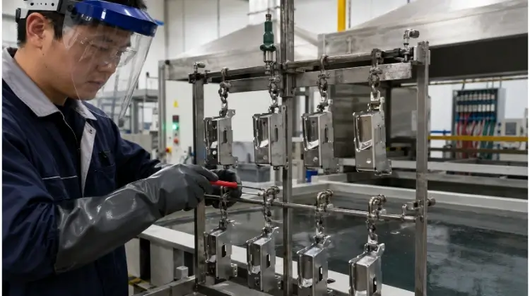
During the process, the part is mounted on a conductive rack (typically made of titanium or copper). Current follows the path of least resistance, which means part geometry directly affects how the metal dissolves.
- High Current Density Zones: Outer corners, sharp edges, and protrusions attract more current. These areas process faster and remove more material.
- Low Current Density Zones: Recesses, grooves, and deep holes receive less current, often resulting in a duller finish compared to the exterior.
- Shadowing: If parts are racked too closely together, they shield each other from the current, leaving under-polished “shadows.”
- Rack Marks: The fixture must grip the part tightly to maintain a stable electrical connection. Because the contact point is shielded from the electrolyte, a small, visible “rack mark” will always remain on the finished part. If the contact area is too small, localized burn marks can occur.
Bath Control and Post-Treatment
The electropolishing bath requires strict control of electrolyte chemistry, temperature, and current density. Time in the tank and the total exposed surface area must be calculated precisely.
When parameters drift, specific defects appear:
- Low current density results in a milky, dull surface without microscopic leveling.
- High current density causes localized pitting, orange-peel textures, or edge burning.
- Excessive treatment time leads to over-polished edges and out-of-tolerance dimensions.
Just as critical is the post-treatment sequence. When the part leaves the bath, the electrochemical reaction must be stopped immediately. The standard flow is an immediate cold water rinse, chemical neutralization, DI-water rinsing, and controlled drying.
Poor drainage or insufficient rinsing leaves a white acidic residue on the part. If the drying process is poorly controlled, water spots will form, which are particularly visible on highly reflective surfaces.
Plan for Material Removal Before Releasing the Drawing
Design for Manufacturing (DFM) in electropolishing requires planning for dimensional changes. If you design a precision part to its final dimensions in CAD and then send it out for electropolishing, the finished part will likely fail inspection.
Removal Allowance and Critical Fits
Because electropolishing removes metal, outside dimensions shrink, and inside dimensions grow. Material removal must be calculated on a per-surface basis.
If a thickness of r is removed from each surface:
- An outside diameter (OD) will decrease by approximately 2r.
- An inside diameter (ID) will increase by approximately 2r.
You must verify the impact of material removal on all critical fits, specifically:
- Bearing bores and press-fit holes
- Locating dowel holes
- O-ring grooves and sealing surfaces
- Datum features used for final CMM inspection
- Internal and external threads
⚠️ Engineering Rule of Thumb:
If your total tolerance band is less than 0.001″ (25µm), electropolishing presents a high risk of out-of-tolerance (OOT) failures. For ultra-precision fits (like H7/g6), you must either under-size/over-size the raw part precisely, or mask the feature entirely.
Actual material removal is rarely perfectly uniform across complex geometries. The final allowance required for your specific part must always be validated through a first-article sample.
Edges, Holes, and Internal Channels
Part geometry dictates fluid dynamics and electrical flow in the bath. Keep these constraints in mind during the CAD phase:
- Sharp Edges: Because outer edges attract higher current density, thin edges and sharp corners will be rounded off. Avoid designing unnecessary razor-thin features.
- Blind Holes: Blind holes trap oxygen gas (a byproduct of the process) and electrolyte fluid. Without proper fluid flow, the bottom of the hole will not polish. Always provide a venting or drainage path if possible.
- Internal Channels: Deep bores and complex internal channels receive almost no current from the external tank cathodes.
- Flat Recesses: Horizontal pockets trap gas bubbles as they rise, creating streaks or unpolished spots.
🛠️ Shop Floor Pro-Tip:
Polishing the inside of a deep pipe or complex internal channel requires fabricating a custom “auxiliary cathode”—a conductive rod inserted directly into the cavity. This significantly increases tooling costs and setup time. If internal finish is not functionally critical, clearly annotate your drawing to specify that the internal finish is exempt.
Masking and Drawing Notes
While masking protects critical tolerances, it is a highly manual, labor-intensive process that can easily double the unit cost of a small CNC part. Do not specify masking “just in case”—use it only when functionally mandatory.
Commonly masked areas include:
- Machined threads
- Bearing seats and press-fit surfaces
- Electrical grounding contacts
- Installed PEM fasteners
Recommended Drawing Note Example:
To avoid ambiguity, specify the standard, the target, and the restrictions clearly on your 2D drawings. (Note: Modify the bracketed values based on your actual part requirements.)
- ELECTROPOLISH STAINLESS STEEL PER ASTM B912.
- FINAL SURFACE ROUGHNESS: Ra ≤ [0.4 µm] ON MARKED SURFACES.
- PROTECT THREADS AND DATUM FEATURES FROM MATERIAL REMOVAL.
- OPTIONAL: PERMISSIBLE RACK CONTACT AREA INDICATED BY [X].
- NO PITTING, BURN MARKS, WATER STAINS, OR VISIBLE RESIDUE.
- FINAL DIMENSIONS APPLY AFTER ELECTROPOLISHING.
Explain Note 4: By explicitly defining a non-cosmetic, non-functional area for the rack contact on your drawing, you prevent the supplier from accidentally leaving a rack mark on a critical sealing face or highly visible cosmetic surface.
When submitting an RFQ (Request for Quote), ensure you explicitly state the material grade, the starting surface condition, permitted material removal, and whether you require an approved appearance sample before full production begins.
What to Check Before Approving Production?
A shiny part is not automatically a compliant part. Before moving from prototype to high-volume production, engineers and quality managers must establish clear, measurable acceptance criteria. Relying on a visual check alone is a guaranteed path to rejected assemblies.
Finish and Dimensional Inspection
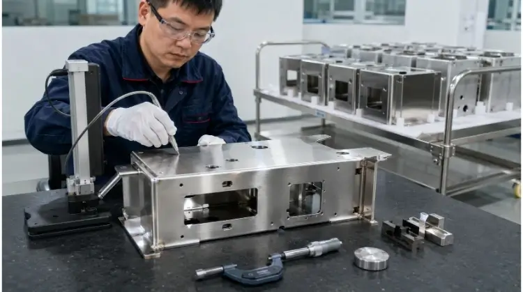
To ensure the electropolished part meets functional engineering requirements, map your inspection methods to specific standards.
| Requirement | Inspection Method |
| Appearance | Visual comparison against an approved physical sample under controlled lighting. |
| Ra and Rz | Contact profilometer (measured at a specifically annotated location). |
| Critical dimensions | Micrometer, go/no-go gauges, or CMM. |
| Material removal | Before-and-after dimensional measurement. |
| Surface defects | Visual or magnified inspection (e.g., 10x loupe) for pitting or burns. |
| Passivation performance | Applicable ASTM test (e.g., copper sulfate or high-humidity test per ASTM A967). |
| Cleanliness | Residue wipe test, water-break test, or particle count. |
| Batch consistency | AQL sampling plan and review of the supplier’s process records. |
Critical Quality Distinctions:
- A bright, highly reflective surface does not mean the Ra specification was met.
- A passing Ra value does not guarantee the part formed a proper passive layer for corrosion resistance.
- Passing a corrosion resistance test does not mean the part is chemically clean or free of acid residue.
- “Acceptable appearance” is subjective. Always establish a physical “golden limit sample” rather than relying on photographs.
Defects and Root Causes
When a First Article Inspection (FAI) fails, the defect usually traces back to pretreatment, current distribution, or bath chemistry. Use this diagnostic table to determine whether the issue requires a design change, a racking change, or a bath adjustment.
| Defect | Likely Cause | Corrective Direction |
| Dull surface | Low current density or poor starting finish. | Review pretreatment cleaning and current parameters. |
| Pitting | Excess current, inclusions in the metal, or bath contamination. | Inspect electrolyte chemistry and reduce current density. |
| Cloudy halo around welds | Heat-Affected Zone (HAZ) modified the alloy’s microstructure. | Passivate or mechanically buff the HAZ prior to electropolishing. |
| Uneven brightness | Poor cleaning or uneven current distribution. | Improve degreasing and adjust part spacing on the rack. |
| Rack burns | Poor electrical contact or insufficient contact area. | Redesign the titanium/copper rack contact points. |
| Streaks | Trapped oxygen gas bubbles moving across the surface. | Change part orientation to allow gas to escape, or increase agitation. |
| White residue | Incomplete rinsing of the acidic electrolyte. | Improve neutralization and DI-water rinsing stages. |
| Rounded edges | Excess material removal at high-current zones. | Reduce treatment time or physically mask the edges. |
| Poor internal finish | Insufficient electrical current reaching interior cavities. | Redesign tooling to include an auxiliary cathode. |
| Water spots | Poor drainage or uncontrolled drying. | Improve part orientation on the rack and use clean, heated forced air. |
Conclusion
Electropolishing is a highly controllable electrochemical process, but it requires precise engineering alignment between the machine shop and the finishing facility.
- Electropolishing improves microscopic surface conditions, increases corrosion resistance, and eliminates micro-burrs, but it does not repair major manufacturing defects like deep scratches or heavy weld scale.
- The final result is determined by the base material, the starting surface finish, the control of current distribution, and the dimensional allowance engineered into the original CAD model.
- Production approval must be objective. It must cover visual appearance, measured roughness, final dimensions, chemical cleanliness, and corrosion requirements using verified inspection methods.
Don’t wait until the First Article Inspection to discover your part needs masking or dimensional adjustments.
Send us your CAD files and critical tolerances. Our manufacturing engineers will provide a free DFM review, detailing the expected material removal, masking requirements, and the true cost drivers for your specific geometry—before you ever cut a single chip of metal.