
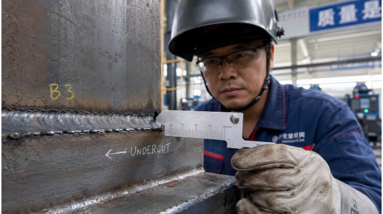
A welding undercut is a structural defect characterized by an unfilled groove melted along the weld edges. Triggered by excessive current or improper travel speed, it thins the base metal and acts as a stress riser, severely compromising the weld’s mechanical strength and fatigue resistance.
This groove creates stress concentration and is a frequent reason for part rejection during quality inspection. Managing undercut is necessary to maintain part strength, meet engineering tolerances, and control rework costs in production.
Why Welding Undercut Affects Welded Parts?
Undercut is more than a visual issue; it changes the mechanical properties of the joint. Understanding its physical impact helps explain why fabrication standards set strict limits on its depth and length.
Reduced effective material thickness
When the arc melts the base metal without depositing enough filler, the resulting groove thins the base plate. For thin-gauge sheet metal (such as 2mm to 3mm enclosures), losing even 0.5mm to an undercut noticeably reduces the load-bearing cross-section.
Because of this material loss, the fabricated part may not meet the original design specifications. If the effective thickness drops below required limits, the part’s overall structural capacity decreases.
Stress concentration at the weld toe
Mechanical loads depend on a smooth material transition across a weld joint. The sharp edge of an undercut groove creates a mechanical notch, which interrupts this load transfer and concentrates stress at a specific point.
Instead of distributing forces evenly across the thicker weld throat, the stress focuses on the thinnest, gouged section of the parent material. This makes the joint significantly more sensitive to bending or tensile forces during operation.
Fatigue cracking under dynamic loads
For parts exposed to continuous vibration or thermal expansion, undercut is a common starting point for micro-cracks. Under repeated stress cycles, the concentrated forces at the notch gradually weaken the grain structure of the metal.
Over time, these micro-cracks can grow and spread through the heat-affected zone (HAZ). This often leads to fatigue failure before the component reaches its expected design lifespan.
Inspection rejection and repair costs
Industrial welding standards (like AWS D1.1 or ISO 5817) have specific tolerance levels for undercut based on the application. Visual testing (VT) easily identifies surface grooves, while ultrasonic testing (UT) detects root undercut, which usually causes the part to fail inspection.
Fixing an undercut generally requires repair welding or light blend grinding. Adding more weld metal introduces a secondary thermal cycle to the part, which increases the risk of warping and adds unplanned labor hours to the production schedule.
What Causes Welding Undercut During Production?
Undercut usually happens when the welding parameters or torch movements are out of balance. It is a process control issue where the joint edges melt but are starved of filler metal.
High heat input and over-melting
Using excessive welding current or voltage causes the arc to melt the base metal too quickly. While operators or programmers may increase parameters to improve travel speeds, this excess heat melts the joint edges faster than the wire can fill them.
The molten base material becomes highly fluid and flows away from the edges. Once the weld pool cools and solidifies, a permanent, unfilled groove is left behind.
Fast travel speed and arc lag
If the torch moves too fast along the joint line, the filler metal does not have enough time to wet out into the edges. The weld pool becomes narrow and physically lags behind the arc force.
Because the torch is moving quickly, the edges of the pool freeze before the molten metal can flow back to fill the gouged areas. This is a frequent issue in high-speed robotic MIG welding if the travel speed is not properly matched to the wire feed rate.
Incorrect torch angle in horizontal joints
The angle of the torch determines where the arc force is directed. In fillet welds or horizontal joint configurations, pointing the torch too directly at one plate will dig aggressively into that specific side.
Gravity can make this worse by pulling the molten puddle downward. This leaves the upper edge of the joint without enough filler metal, usually resulting in a continuous undercut along the top toe of the weld.
Inconsistent weld pool control
When using weave or oscillation techniques, failing to pause at the outer edges of the joint often causes undercut. An edge pause gives the filler metal time to flow into the sides and fuse with the base material.
If the operator or robot sweeps the torch across the center continuously without holding the edges, the middle of the weld builds up too much. Meanwhile, the outer toes remain underfilled and gouged.
Welding Conditions That Commonly Create Undercut
Undercut does not happen randomly. It is more likely to occur under specific production setups and joint configurations where managing heat and gravity becomes difficult. Recognizing these challenging conditions helps fabrication shops plan better welding procedures.
Thin sheet metal welding
When welding thin-gauge materials (such as 1.5mm to 3mm sheets), the base metal heats up and melts very quickly. Operators have a narrow operating window to balance enough heat for proper penetration without melting away the edges.
If the arc force is slightly too high, the thin edges of the joint melt and blow away before the wire can fill the gap. This is a common issue when manufacturing electrical enclosures or custom panels, requiring careful control of amperage and travel speed.
Stainless steel fabrication
In stainless steel fabrication, such as building food-grade hoppers or medical cabinets, heat tends to build up quickly in the part. Because stainless steel does not dissipate heat well, the weld area becomes very hot, making the weld puddle highly fluid but sluggish at the edges.
If the operator does not adjust their travel speed to account for this heat buildup, the edges of the joint will remain unfilled. Managing interpass temperatures and using stringer beads rather than wide weaves are standard requirements to prevent gouging along the weld length.
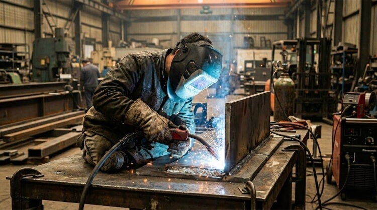
Robotic MIG welding
Robotic welding cells operate at consistent, high speeds, which makes them highly efficient for volume production. However, if the robot’s travel speed is programmed even slightly too fast for the wire feed rate, the edges of the joint will not fill properly.
Unlike a human operator, a robot will not instinctively slow down or change its torch angle if it senses the puddle lagging. If the dwell time (edge pause) is not properly programmed during the setup phase, this can result in a continuous micro-undercut running across an entire batch of production parts.
Vertical weld joints
Welding in the vertical position (either vertical-up or vertical-down) forces the molten metal to work against gravity. In vertical-up joints, the molten puddle naturally wants to drag downward away from the edges.
To keep the puddle from falling, welders often use a weaving motion. If they move across the center too quickly and do not pause long enough at the sides of the weave, gravity pulls the metal to the center, leaving a distinct undercut along both toes of the weld.
Materials That Are More Sensitive to Welding Undercut
The thermal properties of the base material heavily influence how the weld pool behaves. Some metals are naturally more sensitive to edge melting and require stricter parameter control to prevent undercut.
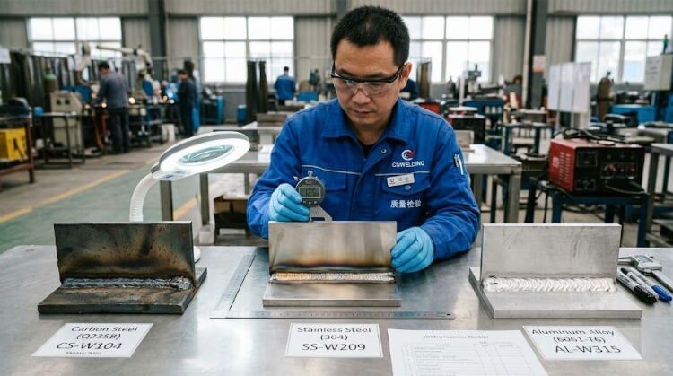
Carbon steel
Carbon steel (such as mild steel or Q235) is generally the most forgiving material to weld. It conducts heat evenly, which allows the weld pool to form and solidify in a predictable manner.
When undercut happens in carbon steel fabrication, it is often because operators increase voltage to burn through mill scale or surface rust, which inadvertently melts the joint edges too quickly. Proper material preparation and standard parameter adjustments usually resolve the issue quickly.
Stainless steel
Grades like 304 and 316 stainless steel have high thermal expansion and poor thermal conductivity. This means the welding heat stays localized at the joint, keeping the edges molten for a longer period while the center begins to cool.
Because the edges stay soft and the puddle is sluggish, undercut easily forms if the heat input is not strictly controlled. Limiting overall heat input and monitoring cooling times are necessary when welding stainless steel to avoid edge gouging.
Aluminum alloys
Aluminum transfers heat extremely fast, which means it requires a high initial current to establish the weld pool. However, this high arc energy can easily gouge the edges of the joint if the operator is not careful.
Additionally, if the cleaning action (AC balance) during TIG welding is set too wide, the edges of the base metal melt away instantly. Because aluminum is softer, the resulting undercut is typically sharper and deeper than in steel, making the component even more susceptible to early fatigue failure.
How Fabrication Shops Control Welding Undercut?
Consistent weld quality does not rely solely on operator skill; it depends on strict process controls on the shop floor. Fabrication shops manage undercut by standardizing equipment settings and qualifying procedures before production begins.
Parameter balancing
The most direct way to control undercut is strictly managing the ratio between voltage, wire feed speed, and travel speed. If the voltage is too high for the wire feed rate, the arc melts too much base material without filling it.
Fabrication shops often use synergic welding machines that automatically adjust voltage and current together. For standard setups, supervisors lock in the parameters on the machine interface so operators stay within a specific “sweet spot” that guarantees proper edge fill.
Torch movement stability
For manual welding, preventing undercut requires consistent muscle memory and torch positioning. The operator must maintain a steady work angle—typically 45 degrees for fillet welds—to ensure the arc force is distributed equally between both base plates.
When weaving is required, welders are trained to execute a distinct pause at the toes of the weld. This momentary hold allows the molten filler metal to wash out and tie into the gouged edges before moving the torch back across the center.
Robotic welding tuning
In automated manufacturing, controlling undercut requires precise programming during the initial setup. Programmers adjust the dwell time at the edges of the weld path, forcing the robot arm to hold position for a fraction of a second to allow filler metal transfer.
Additionally, engineers often use pulsed MIG/MAG waveforms for robotic applications. Pulsed welding controls the heat input by alternating between high peak currents and low background currents, lowering the overall thermal load on the base metal while still pushing filler wire into the joint.
Welding procedure qualification
Before mass production starts, professional fabrication shops develop a Welding Procedure Specification (WPS). This document dictates the exact parameters, travel speeds, and gas mixtures required for a specific material grade and thickness.
To prove the WPS works, the shop performs a Procedure Qualification Record (PQR). This involves welding test coupons, cutting them cross-sectionally, and performing a macro-etch test to visually ensure the chosen parameters do not cause hidden root or toe undercut, locking in the process for the production run.
Welding Undercut Inspection and Repair Standards
Undercut is not an automatic reason for scrap; acceptability depends on the depth of the groove and the engineering requirements of the part. Quality control teams rely on established international codes to determine if a part passes, requires rework, or must be rejected.
AWS D1.1 limits
Quality inspectors typically use a V-WAC gauge (undercut gauge) to physically measure the depth of the groove before comparing it to code limits. For primary structural components subjected to static loads, the AWS D1.1 Structural Welding Code generally restricts undercut depth to 1mm (1/32 inch) depending on the base metal thickness.
For parts subjected to cyclic loads (dynamic stress), the limits are much stricter. Even a minor undercut of 0.25mm (0.01 inch) can be cause for rejection if the weld is oriented transverse to the tensile stress, as this geometry poses a severe fatigue risk.
ISO 5817 acceptance levels
In global manufacturing, ISO 5817 classifies weld imperfections into three quality levels: Level B (Stringent), Level C (Intermediate), and Level D (Moderate). The allowable undercut depth scales with the required quality level and the plate thickness.
For high-stress applications requiring Level B quality, undercut is heavily restricted and often required to be completely smooth. Level D allows for slight undercuts, but the groove must still be free of sharp edges that could trap stress.
Blend grinding
When an undercut is very shallow and falls just outside of acceptable limits, shops usually use blend grinding rather than welding. An operator uses a die grinder or flap disc to smooth out the sharp notch, typically creating a 3:1 taper into the base metal.
This removes the stress concentration point without introducing new heat into the part. It is a code-compliant repair method as long as the grinding does not reduce the base metal thickness below the original engineering tolerance, provided the grinding marks run parallel to the direction of primary stress.
TIG repair welding
If the undercut is too deep for grinding, the joint must be repaired by adding filler metal. TIG (GTAW) repair welding is typically used for this process because it offers precise heat control and allows the operator to wash the filler metal smoothly over the weld toe.
However, repair welding is strictly monitored. Adding more weld metal introduces a secondary thermal cycle, expanding the heat-affected zone and increasing the risk of part distortion. In sheet metal fabrication, shops try to avoid repair welding whenever possible to maintain dimensional accuracy.
Conclusion
Welding undercut is a direct result of unbalanced process variables, causing the base metal to melt faster than the filler metal can replace it. While it may look like a simple surface groove, it significantly reduces the effective thickness of the material and creates mechanical notches that invite fatigue failure. Preventing it requires strict parameter control, stable torch movement, and qualified welding procedures tailored to the specific material.
Looking for a manufacturing partner who understands strict weld quality?
At TZR, we apply rigorous quality control and standardized welding procedures to every project. With over 10 years of experience in sheet metal processing and CNC machining, our engineering team ensures your parts meet strict tolerances—from rapid prototyping to mass production. Send us your CAD files or technical drawings today for a DFM (Design for Manufacturing) review and a competitive quote.
FAQs
What is the acceptable depth of welding undercut in structural welding standards?
Acceptable depth depends on the standard and the load type. Under AWS D1.1 (static loads), undercut is generally limited to 1mm (1/32 inch). For dynamic/fatigue loads, the limit drops to 0.25mm (0.01 inch) or is rejected entirely. Under ISO 5817, high-stress Level B applications require a completely smooth transition (zero undercut), while Level D allows slight grooves.
Can welding undercut be repaired without weakening the base material?
Yes, but the repair method depends on the depth of the groove. Shallow undercuts are usually resolved using blend grinding. If the undercut is too deep, it requires TIG repair welding.
Is welding undercut more serious in thin sheet metal than in thick plate welding?
Yes, significantly more serious. Thick structural plates have enough mass to absorb minor edge gouging. In sheet metal fabrication, the margin for error is virtually zero. For example, a 0.5mm undercut on a 2mm panel reduces the load-bearing cross-section by 25%. This severe material loss risks immediate structural failure under load and increases the chance of burn-through during production.
How can welders prevent undercut during high-speed production welding?
Preventing undercut at high speeds requires strict parameter balancing. The voltage must be carefully matched to the wire feed speed so the arc does not gouge the metal faster than the filler can be deposited.