
 English
  Spanish
  German
  Russian
  Italian
  French
Welding thin sheet metal is an exercise in strict heat management. Unlike heavy structural plates that naturally absorb and dissipate excess thermal energy, thin gauges (typically anything under 3mm or 11-gauge) have almost no thermal mass to act as a buffer.
In thin sheet fabrication, heat input dictates the entire outcome. If you pump too much amperage into the joint, the material reaches its melting point through its entire cross-section, causing the weld pool to simply drop out. Conversely, moving too fast to avoid burn-through often results in cold lap and lack of fusion.
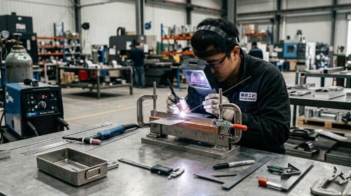
Why Thin Metal Fails During Welding?
The margin for error when welding sheet metal is incredibly narrow. Understanding the exact sequence of thermal events on the shop floor is the first step to controlling the outcome and reducing scrap rates.
Heat buildup
When an arc strikes, the localized temperature spikes instantly. In thick plates, the surrounding material acts as a massive heat sink, pulling thermal energy safely away from the weld zone.
In thin sheet metal, there is nowhere for that heat to go. The thermal energy quickly saturates the immediate area, causing the base metal to rapidly lose its structural integrity before the arc even moves forward.
Burn-through
Burn-through (or melt-through) occurs when the heat buildup exceeds the material’s capacity to hold the molten puddle. The arc literally blows a hole through the joint, ruining the part in a fraction of a second.
This failure mode is highly predictable. It almost always happens when the travel speed is too slow, the wire diameter is too thick (e.g., using 1.2mm wire on 1.0mm sheet), or the voltage is set too high for the specific gauge.
Residual stress
Metal expands when heated and contracts as it cools. When a liquid weld bead solidifies and cools to room temperature, it naturally wants to shrink.
However, the adjacent, cooler base metal does not shrink at the same rate. This differential in thermal contraction locks massive physical forces into the structure, known as residual stress.
Panel distortion
When the residual stress from the cooling weld exceeds the yield strength of the thin sheet metal, the physical structure gives way. This manifests as warping, buckling, or “oil-canning” across the entire flat panel.
While a burn-through is a localized defect that can sometimes be patched, severe distortion ruins the dimensional accuracy of the entire assembly. This directly leads to fit-up failures in downstream manufacturing steps and skyrockets your scrap costs.
Choosing the Right Welding Process
Specifying the correct welding process for thin metal isn’t just about making the weld; it comes down to balancing heat input, production volume, and cosmetic requirements. What works perfectly in a custom prototyping shop may fail miserably in mass production.
Short-circuit MIG
Short-circuit gas metal arc welding (GMAW) is the baseline standard for thin carbon steel. Instead of a continuous arc, the wire feeds into the puddle, creates a short circuit, melts, and then re-ignites—often over 100 times per second.
This rapid on/off cycle keeps the average heat input relatively low. It makes short-circuit MIG a reliable, highly cost-effective choice for general steel assemblies down to about 0.8mm (22-gauge).
Pulse MIG
Pulsed MIG relies on advanced inverter technology to alternate between a high peak current (to melt the wire) and a low background current (to maintain the arc without adding excess heat). It pinches off exactly one droplet of molten wire per pulse.
This process provides the fast travel speed of standard MIG but drastically reduces the heat-affected zone (HAZ) and virtually eliminates post-weld spatter. It is highly effective for thin aluminum and stainless steel where heat control is critical.
TIG welding
Tungsten inert gas (TIG) welding offers the ultimate control over amperage and filler metal deposition. Because the heat source (the tungsten arc) is separate from the filler wire, operators can melt the base metal with surgical precision, making it the go-to process for highly cosmetic, zero-spatter joints in medical or food-grade stainless steel.
However, TIG is inherently slow—often running at a fraction of the speed of MIG—and requires highly skilled manual labor. This makes it the most expensive process per part, usually reserved only for aesthetic or critical-sealing applications.
Laser welding
For high-volume sheet metal manufacturing, laser welding has aggressively superseded traditional arc processes. A laser beam provides an extremely high energy density, allowing for rapid travel speeds and a microscopic heat-affected zone.
Whether executed via handheld units or automated robotic cells, laser welding delivers deep penetration with near-zero distortion and often entirely eliminates the need for expensive post-weld grinding. While the initial capital equipment cost is high, the piece-part cost and yield rates are unmatched for thin-gauge production runs.
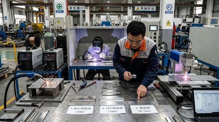
Fit-Up and Fixturing Control
In sheet metal fabrication, welding is only as good as the preparation. Trying to fix poor sheet metal cutting or bending with a welding torch will almost always result in scrap. Controlling the physical layout before striking an arc is your absolute best defense against heat damage.
Zero-gap fit-up
A gap in a sheet metal joint is essentially two exposed, sharp edges. Because edges have zero thermal mass, they melt instantly when the arc hits them, guaranteeing a burn-through.
The golden rule for thin metal: The gap must never exceed the diameter of your welding wire. If you are using 0.8mm wire, a 1.0mm gap is a guaranteed failure. If you can see light through the joint, send the part back to the press brake.
Copper backing bars
One of the most effective ways to manage heat is to introduce a temporary heat sink. Clamping a copper or aluminum backing bar directly behind the weld joint creates a “heat trap.”
Because copper has exceptionally high thermal conductivity and will not fuse to the steel weld pool, it serves a dual purpose. It rapidly pulls thermal energy out of the steel, while physically supporting the molten puddle so it cannot drop through the back of the joint.
Rigid clamping
Distortion happens when heated metal is allowed to move. The simplest way to stop it is to lock the assembly down completely.
A standard shop heuristic: For sheet metal under 1.5mm (16-gauge), place a heavy-duty clamp every 3 to 4 inches (75-100mm) along the joint. You must keep the part rigidly clamped not just during welding, but until the steel has cooled entirely to room temperature.
Pre-bending
For flat panel assemblies where some distortion is physically unavoidable, experienced fabricators use pre-bending, also known as pre-setting camber.
This involves intentionally clamping the sheet metal with a reverse curve (typically 2 to 3 degrees in the opposite direction). As the weld bead cools and naturally shrinks, the massive contraction forces pull the metal back into a perfectly flat, dimensional state.
Reducing Heat Input During Welding
Once the part is fixtured, lowering your heat input is not just about randomly turning down dials. It requires a coordinated adjustment of wire size, voltage, and the operator’s travel speed.
Wire diameter
You cannot effectively weld thin sheet metal with thick wire. Standard 1.2mm (0.045″) wire requires too much base amperage to melt, which means you will blow a hole through thin-gauge stock before the wire even puddles.
Step down to a 0.6mm (0.023″) or 0.8mm (0.030″) solid wire. A smaller wire diameter requires significantly less current to reach its melting point, allowing you to deposit filler metal while keeping the base panel relatively cold.
Voltage control
Voltage dictates the width of your arc cone and how fluid the weld puddle becomes. Higher voltage means a wider, hotter arc that rapidly spreads thermal energy across the panel.
For thin gauges, drop the voltage until the arc becomes extremely tight. You are looking for clear auditory feedback: the sound of the arc should shift from a breathy “hiss” to a rapid, crisp “bacon-frying” crackle. This indicates the short-circuit transfer is operating at its coolest, most efficient state.
Travel speed
When welding thin metal, lingering is your enemy. The novice instinct is to slow down to ensure the joint is fusing properly.
In reality, slowing down guarantees a burn-through. With sheet metal, you must physically outrun the heat saturation. The goal is to move the torch fast enough to fuse the root, but quick enough to leave the area before the surrounding metal turns red-hot.
Stitch welding
Running a continuous, unbroken weld bead on thin metal will act like a zipper, pulling the panel into a warped mess as heat accumulates linearly.
Instead, use stitch welding (or skip welding). Place short, 1-inch (25mm) welds at various locations along the joint. Use a randomized sequence (e.g., weld position 1, then 4, then 2, then 5). This prevents thermal energy from ever concentrating in one zone.
Welding Thin-to-Thick Joints
Joining a 1mm (20-gauge) sheet to a 5mm structural bracket is a classic shop-floor headache. The hot parameters required to penetrate the thick plate will vaporize the thin sheet, while the cold settings for the thin sheet will result in a weak, rejected “cold lap” on the thick plate.
Arc bias
The solution is strict directional control. Never point the welding torch directly at the root or center of the joint.
Instead, bias the arc angle heavily toward the thick material. Follow the 80/20 rule: aim 80% of the arc’s heat directly onto the 5mm plate, leaving only 20% to passively interact with the fragile sheet metal.
Heat balance
By pointing the arc at the thick plate, you are utilizing its greater mass as a primary heat sink. It absorbs the high amperage needed for structural penetration without failing.
Once a fluid puddle is established on the thick plate, the operator takes control of the heat transfer. You use the thermal energy radiating from the molten puddle itself to melt the thinner material, not the raw, destructive heat of the direct arc.
Edge melt control
The critical moment is how the puddle interacts with the thin edge. You must let the molten metal gently “wash” over the seam.
Use a tight, continuous “C” or “e” motion with the torch. Keep your main dwell time firmly on the thick plate, whip the puddle quickly over to the thin sheet for just a fraction of a second to catch the edge, and immediately pull it back. This guarantees solid fusion while keeping the thin metal completely safe from burn-through.
Material-Specific Welding Challenges
A parameter setting that creates a flawless bead on mild steel will instantly vaporize aluminum or warp stainless beyond repair. Understanding the thermal properties of your specific alloy is the prerequisite for thin-metal success.
Heat retention in mild steel
Mild steel is the most forgiving material, but it is highly susceptible to heat retention. It holds thermal energy long after the arc is extinguished.
The visual cue: Watch the dull red glow of the weld pool. If you try to overlap a stitch weld while the previous crater is still glowing red, the combined heat saturation will instantly blow a hole through the panel. Always let the localized area return to a cold, dark state before striking an arc near it again.
Distortion risk in stainless steel
Stainless steel is a thermal nightmare for thin sheet fabrication. It possesses a drastically lower thermal conductivity than mild steel, meaning the heat stays trapped exactly where you weld it. Worse, it has a 50% higher rate of thermal expansion.
This combination guarantees extreme, localized warping. The shop-floor rule: When welding stainless under 1.5mm (16-gauge), you must use heavily clamped copper chill bars and strictly limit your arc time. If the heat-affected zone (HAZ) turns a dark, sugary gray or black, you have overheated the joint and destroyed the metal’s corrosion resistance. You want light straw or salmon colors.
Heat transfer in aluminum
Aluminum behaves exactly the opposite of stainless steel. It has massive thermal conductivity, meaning the entire panel acts as a giant heatsink, rapidly pulling energy away from the torch.
The hidden danger: Aluminum gives no visual warning before it melts—it does not turn red. You need a hot, high-amperage start to establish the puddle, but within 3 to 5 seconds, the entire surrounding area becomes heat-saturated. The puddle will suddenly widen, and the bottom will drop out entirely. You must aggressively accelerate your travel speed the further you move down the joint.
Zinc contamination in galvanized steel
Galvanized sheet metal is coated with a layer of zinc to prevent rust. However, zinc boils and vaporizes at roughly 900°C (1650°F)—far below the melting point of the underlying steel.
Welding directly over this coating causes the zinc vapor to violently explode through the molten weld pool, resulting in massive porosity and erratic arc behavior.
The absolute requirement: Use a flapper wheel to grind away the zinc coating at least 1/2 inch (12mm) back from both sides of the joint before welding.
Post-Weld Finishing and Correction
In modern sheet metal manufacturing, post-weld finishing is not about brute-force blacksmithing; it is about precision blending. Aggressive finishing techniques can actually ruin a perfectly welded thin panel by introducing a secondary wave of heat and distortion.
Low-heat grinding
Taking a hard grinding wheel to a thin sheet metal weld is a critical mistake. The friction generates intense localized heat, causing the panel to warp violently after the welding is already done.
The modern approach: Ditch the hard rocks. Use ceramic-alumina flap discs or resin-fiber discs. Let the sharp abrasive do the cutting, not the pressure of your hands.
The bare-hand test: If you cannot comfortably place your bare hand flat on the metal immediately after grinding, you are pushing too hard and generating too much friction.
Cosmetic surface blending
For cosmetic enclosures (like medical devices or food-service equipment), the weld must disappear seamlessly into the base material.
Avoid aggressive cross-grinding. Instead, use non-woven abrasive conditioning belts (like Scotch-Brite) or dual-action (DA) orbital sanders. The goal is to feather the weld metal into the surrounding panel using progressively finer grits, matching the linear grain direction of the factory finish so the joint becomes invisible under final powder coat or anodizing.
Distortion correction
Even with perfect fixturing, minor “oil-canning” or buckling can occur. Modern shops do not beat the metal flat with a hammer and anvil.
Instead, use controlled thermal shrinking. An operator runs a TIG torch (without filler wire) rapidly over the stretched, buckled area to create a tiny, localized hot spot. They immediately quench it with a blast of compressed air or a wet rag. The rapid cooling forces the metal to aggressively contract, pulling the warped panel taut and flat like a drumhead.
DFM for Thin Sheet Metal Parts
The cheapest, most perfectly executed weld is the one you don’t have to make. True manufacturing efficiency begins in the CAD environment. By designing parts specifically for the realities of sheet metal fabrication (DFM), engineers can drastically reduce costs, eliminate heat distortion, and ensure consistent quality.
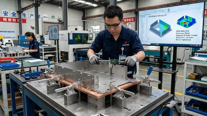
Bend instead of weld
Never specify a welded outside corner joint if the part can be formed on a CNC press brake.
A press brake can fold a 90-degree flange on a 1.2mm steel sheet in about 30 seconds at a cost of pennies, yielding perfect dimensional accuracy and zero thermal input. A cosmetically ground, welded corner on that same part will take ten minutes, introduce severe heat stress, and cost exponentially more in manual labor.
Joint accessibility
Welding torches have physical mass. A common engineering mistake is designing weld seams deep inside narrow, U-shaped channels or behind tight flanges.
The access rule: Always leave a minimum 45-degree clear access cone around the intended weld path. If the operator cannot fit the gas nozzle into the joint, they cannot properly shield the weld pool with gas, guaranteeing a weak, porous, and heavily spattered joint.
Weld location
Heat travels, and when it reaches a high-precision feature, it ruins the tolerance. Placing a weld directly next to a machined hole or a press-brake bend line will cause that feature to pull out of round or shift out of alignment as the metal cools.
The 3X Rule of Thumb: Keep all weld seams at least a distance of three times the material thickness away from any critical holes, slots, or bend radii. This provides a sufficient buffer zone to absorb the thermal contraction.
Stiffening ribs
Rather than fighting thermal distortion after it happens, design the physical structure to resist it.
During the flat-pattern laser cutting and punching phase, incorporate stamped dimples, offset jiggles, or embossed stiffening ribs running parallel to the intended weld zones. These formed features add massive structural rigidity to the thin sheet, physically fighting against the weld’s shrinkage forces and acting as a built-in anti-warpage mechanism.
Conclusion
Thin sheet metal welding is not controlled by skill alone. It is controlled by heat. Once heat input goes beyond the limit of the material, defects like burn-through and distortion appear quickly.
The most stable results come from matching three elements together: the right welding process, proper fixture control, and correct heat management strategy. When these three are aligned, thin sheet welding becomes repeatable in production instead of relying on operator experience.
If you are developing thin-walled metal parts, prototyping enclosures, or moving from sample production to mass production, we can support you with process selection, DFM review, and welding solutions based on your drawing and application requirements.
Send your drawings or requirements, and we will review the manufacturability and recommend a stable welding process for your parts.