
 English
 Spanish
 German
 Russian
 Italian
 French

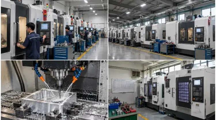
A CNC machining center is an advanced manufacturing machine equipped with an automatic tool changer (ATC) and a tool magazine. Unlike standard CNC mills, it completes milling, drilling, and tapping in a single setup, eliminating the manual tool changes and reclamping that cause tolerance stacking and scrap.
The core value of a machining center is process consolidation. By automating tool changes and utilizing appropriate fixturing, it minimizes the need for an operator to unclamp and reposition the part. However, whether a specific machine can successfully manufacture a part depends entirely on its work envelope, tool accessibility, workholding strategy, and the required tolerances.
Before diving into design rules and hourly rate calculations, use the quick reference below to understand which machine configuration typically aligns with your part profile:
| Part Profile | Recommended Configuration | Primary Evaluation Factor | Relative Hourly Rate |
| Flat plates, shallow pockets, standard holes | 3-Axis Vertical Machining Center (VMC) | Number of setups needed for side and bottom features | $$ (Lowest base rate) |
| Repeat runs of multi-sided box parts | Horizontal Machining Center (HMC) | Tombstone fixture compatibility and batch size | $$$ (Offset by volume efficiency) |
| Multi-angle holes and angled faces | 3+2 Positional Machining | Rotary range limits and tool reach | $$$$ |
| Sweeping curves requiring dynamic tool tilt | Full 5-Axis Simultaneous Machining | Toolpath strategy and collision risks | $$$$$ (Highest rate) |
| Heavy or oversized structural parts | Gantry or Bridge-Style Center | Table load limits and part support strategy | Varies heavily by size |
Note: This table serves as a baseline screening tool and does not replace a formal Design for Manufacturability (DFM) review of engineering drawings.
What a Machining Center Does and How It Works
A machining center consolidates multiple discrete metal-cutting processes into one automated cycle.
Common Operations
| Operation | Target Feature | Primary Application |
| Milling | Flat surfaces, slots, pockets, contours | Removing bulk material to shape the core geometry. |
| Drilling | Through-holes and blind holes | Establishing initial holes for fasteners or subsequent operations. |
| Boring & Reaming | Existing holes | Opening existing holes to precise tolerances and improving surface finish. |
| Tapping & Thread Milling | Internal threads | Cutting threads for screws and fittings. |
Equipment Distinction: Operations like precision grinding or turning (mill-turn) require specialized spindle attachments and specific machine configurations. A standard CNC mill requires manual tool changes; a machining center is a CNC mill with an ATC; a turning center rotates the workpiece rather than the cutting tool.
Core Systems
A machining center relies on several interconnected systems to maintain precision under cutting loads.
- Spindle: Delivers rotational speed (RPM) and cutting torque. High RPM is used for small tools and soft metals, while high low-end torque is necessary to push cutters through hard alloys.
- Toolholders: Secure the cutter to the spindle. Standard collets work well for general tasks, but shrink-fit or hydraulic toolholders are required to minimize runout (wobble) for tight-tolerance or high-speed machining.
- Feed System (Ball screws and Linear guides): Translates CNC commands into physical axis movement. The stiffness of this system dictates positioning accuracy and vibration resistance during heavy cuts.
- Worktable & Fixturing: Holds the raw material. If the fixturing is weak or the part lacks support, it will deflect under cutting pressure, ruining dimensional accuracy regardless of how precise the machine is.
- Coolant System: Flushes chips and controls heat. Standard flood coolant is sufficient for aluminum, but Through-Spindle Coolant (TSC) at high pressure (e.g., 1,000 PSI) is often mandatory for deep-hole drilling in tool steel to prevent chip recutting and tool breakage.
- Control System: Processes the G-code. Processing speed matters heavily for complex 3D toolpaths, ensuring the tool does not hesitate and leave dwell marks on the surface.
Tool Changing
The Automatic Tool Changer (ATC) is what allows a machining center to run unattended. If a housing requires face milling the top surface, drilling a bolt pattern, and tapping those holes, the tool magazine stores the face mill, drill bit, and tap. The ATC mechanism physically swaps these tools in and out of the spindle in seconds.
It is important to distinguish between changing tools, exchanging pallets, and reclamping. The ATC changes tools automatically. An automatic pallet changer (APC) swaps entire workpieces in and out of the cutting zone. Reclamping, however, requires a human operator to unclamp the part and flip it to expose unmachined sides.
The standard production workflow follows this sequence:Process Planning → CAM Programming & Verification → Setup & Tool Offsets → First Article Machining → Quality Inspection & Production Run.
Choosing the Right Configuration for Your Parts
Selecting the correct machining center requires matching the machine’s kinematic structure to the part’s geometry and the anticipated production volume.
Vertical vs. Horizontal
Vertical Machining Centers (VMCs) orient the spindle vertically, clamping parts flat on the table. They work well for plates, shallow molds, and low-volume brackets. Because gravity pulls chips down into the part, deep pockets require aggressive coolant flushing to prevent tool wear.
Horizontal Machining Centers (HMCs) orient the spindle horizontally. Gravity naturally pulls chips away from the cutting zone. HMCs are usually paired with “tombstone” fixtures and dual-pallet systems (APC). This allows one pallet holding 8 to 16 parts to be machined inside, while the operator loads fresh material onto the second pallet outside. This configuration is usually the standard for high-volume production of multi-sided box parts, like pump housings or manifolds.
Axis Configuration
Axis count dictates how many sides of a part can be machined without manual reclamping.
- 3-Axis: The spindle moves in X, Y, and Z. The tool always remains vertical.
- 4-Axis Indexing: Adds a rotary table (usually the A-axis).
- 3+2 Positional Machining: Tilts the part using two rotary axes, locks the axes in place, and performs standard 3-axis milling on that angled plane.
- Full 5-Axis Simultaneous Machining: All five axes move continuously at the same time to allow the side of the endmill to follow complex, warped surfaces.
Engineering Note: More axes do not automatically mean better quality. A heavy, cast-iron 3-axis machine offers significantly more rigidity for roughing hard steels than a light 5-axis trunnion machine. Only specify 5-axis machining when continuous curves or severe setup reductions demand it. Note that axis count and spindle orientation (VMC/HMC) are separate specifications.
Capacity and Materials
Machine specifications must align with both the physical size of the part and the machinability of the material.
| Check Item | What to Confirm |
| Work Envelope | Clearance for the raw billet, fixture, longest tool, and full rotary swing limits. |
| Load Capacity & Support | Part weight, center of gravity, and the weight limits of the trunnion or table. |
| Spindle Performance | Sufficient power and torque at the specific cutting RPM required for the material. |
| Machining Stability | Machine frame rigidity, tool overhang limits, and part clamping strength. |
| Coolant & Chip Removal | Appropriate coolant pressure (e.g., TSC) and chip conveyor volume for the material type. |
Different materials dictate entirely different machine requirements. Machining 7075 Aluminum relies on high RPM (>12,000) and fast feed rates. Conversely, cutting Titanium or Inconel 718 depends on low RPM (<1,000), extremely high spindle torque, and rigid box-way construction to prevent work hardening and machine chatter. Do not apply unified parameters across different alloys.
Case Example: Consider an aluminum electronics housing with a deep internal cavity, side sensor ports, and cross-drilled mounting holes. An engineering team must weigh the lower hourly rate of a 3-axis VMC (which requires three separate manual setups and risks tolerance stacking) against the higher hourly rate of a 3+2 positional setup (which guarantees concentricity between side ports by machining them in a single clamping).
Part Design Rules That Reduce Machining Difficulty
Certain design features force a machine shop to use smaller tools, slow down feed rates, or design custom fixtures. Understanding these limitations during the CAD phase prevents unnecessary cost increases.
Corners and Cavities
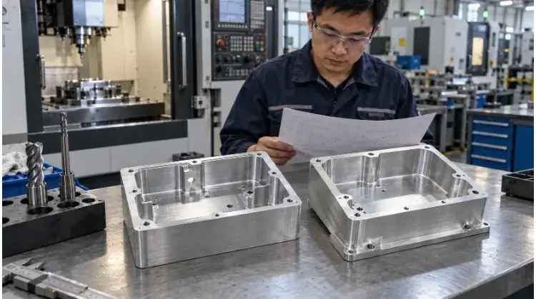
Because end mills are cylindrical, they leave a radius at the intersection of two vertical walls. Designing a perfectly sharp internal corner (zero radius) means the CNC machine cannot cut it with a standard end mill.
- Internal Radii Limits: The corner radius on your print dictates the maximum diameter of the tool the shop can use. A 2mm radius restricts the shop to a 4mm end mill. If that cavity is 40mm deep, a 4mm end mill has a length-to-diameter (L:D) ratio of 10:1. This extreme overhang causes tool deflection and severe chatter.
- The 1/3 Rule: To maintain machining stability in deep pockets, design the internal corner radius to be at least 1/3 of the cavity depth. This allows the shop to use a thick, rigid cutter.
- Corner Relief: If a mating part (like a square block) must fit into the cavity, do not demand a sharp internal corner. Instead, design a “dog-bone” or circular corner relief. This allows the machinist to use a larger, faster tool to clear the corner entirely.
Walls and Clamping
Machining involves aggressive physical force. The part must withstand this force without deflecting, and the machine must have a place to hold the raw material.
- Wall Thickness and Residual Stress: Cutting thin walls (under 1.5mm for aluminum, or 0.8mm for steel) is risky. Furthermore, when machining large aerospace aluminum plates (like 7075-T6), removing too much material asymmetrically releases internal residual stress, causing the plate to bow like a potato chip after it is unclamped from the vise. We mitigate this by taking roughing passes on both sides before finishing.
- Clamping Features: A machinist needs parallel, flat surfaces to grip the billet in a vise. If your design is entirely composed of organic curves, the shop cannot hold it. They will have to mill custom “soft jaws” to match your part’s contour, or you will need to add sacrificial clamping bosses (tabs) to the CAD model that are machined off in a secondary operation. Both options add setup time.
- The Base Plate: The bottom of the raw billet is clamped in the vise. After the top and sides are machined, the part must be flipped to face off the remaining raw material on the bottom. Even a 5-axis machine cannot machine the surface it is being held by.
Tolerances and Datums
Applying a blanket ±0.01mm (±0.0004″) tolerance across an entire drawing forces the shop to inspect every single feature with a Coordinate Measuring Machine (CMM) and run the machine at its slowest, most conservative feed rate.
- The Cost of Precision: Tightening a tolerance from standard ISO 2768-m to ±0.005mm on a simple bore doesn’t just add 10% to the cost; it often triples (3x) the cycle time because it forces the machinist to stop the machine, take a manual measurement, adjust wear offsets, and take a spring pass. Reserve tight tolerances only for bearing press-fits, dowel pin alignments, or dynamic sealing surfaces.
- Datum Selection: The datums (reference planes) you select on your drawing dictate how the machinist sets up the part. If a hole’s location is dimensioned from a datum on the opposite side of the part, the machinist must machine that opposite side first, creating a dependency that limits their processing options. Whenever possible, dimension features from datums that can be machined in the same setup.
Case Example: The Aluminum Housing If the aluminum housing mentioned earlier features a 45mm deep cavity with 1mm internal corner radii, the shop must plunge a fragile 2mm end mill down 45mm. The feed rate will crawl, and tool breakage is highly likely. Changing that radius to 15mm allows the shop to rough the pocket out in seconds with a heavy 30mm indexable face mill. If the housing also features 1mm thick exterior walls, the clamping pressure of a standard vise might crush the part, forcing the shop to build a custom fixture.
Controlling Accuracy and Checking Finished Part Quality
Accuracy is not a single button a machinist presses; it is a controlled mitigation of physical errors across the entire manufacturing process.
Accuracy Terms
Do not confuse a machine tool builder’s marketing specifications with the final tolerance of your part.
- Positioning Accuracy: How accurately the machine’s ball screws can move the spindle to a programmed coordinate in free space (e.g., ±0.005mm).
- Repeatability: How consistently the machine can return to that exact same coordinate over multiple cycles (e.g., ±0.002mm).
- Part Tolerance: The final measured accuracy of the physical part.
A machine with ±0.005mm positioning accuracy cannot guarantee a ±0.005mm part tolerance. Once a cutting tool engages metal, cutter deflection, fixture flexing, and the thermal expansion of the workpiece all introduce error. If a shop promises you machine-spec accuracy on a finished part without asking about your material or fixturing, they are overpromising.
Process Control
Maintaining tolerance across a batch of 500 parts requires managing variables as the machine runs.
- Thermal Growth & Tool Wear: As the spindle runs at 12,000 RPM, it heats up and physically expands in the Z-axis. Cutting tools also wear down. High-end machining centers utilize integrated thermal sensors and laser tool presetters (like Renishaw or Blum) inside the machine to automatically measure tool wear and thermal spindle growth, updating offsets via the CNC control before the next cycle begins.
- Clamping Consistency: If an operator tightens a vise with 50 lbs of force on part #1, and 80 lbs of force on part #2, the parts will deflect differently, resulting in varying dimensions. High-quality production relies on torque wrenches, hydraulic vises, or pneumatic clamps to ensure identical clamping force on every cycle.
- First Article vs. Production: A shop can often hold an incredibly tight tolerance on a single First Article piece by taking slow, manual “spring passes.” Maintaining that same tolerance across 1,000 parts at production speeds is a completely different engineering challenge.
Inspection Planning
Quality must be verified using the correct metrology equipment, and standard documentation is critical for overseas procurement.
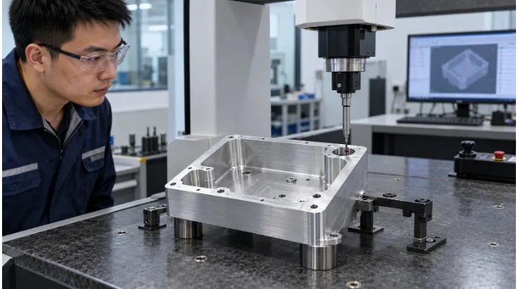
- Gauging vs. Measuring: A coordinate measuring machine (CMM) measures the exact diameter of a hole. A go/no-go plug gauge simply confirms if the hole is within the acceptable limit. Gauges are faster for production runs, while CMMs provide the data needed for formal reporting.
- Pre- vs. Post-Processing: If your part requires Type III Hard Anodizing, it will add up to 0.05mm of thickness to the surfaces. Your drawing must explicitly state whether the dimensions apply before or after plating. If a tight-tolerance dowel hole is measured after machining but before anodizing, it will be undersized once the part returns from the plater.
- Documentation: Ensure your shop can provide AS9102 First Article Inspection (FAI) reports or Material Test Reports (MTR) with full traceability, as these are often hard requirements in the automotive, medical, and aerospace sectors.
Case Example: Inspecting the Housing For the aluminum housing, the shop uses a CMM for the First Article Inspection to verify the true position of the cross-drilled side ports relative to the main cavity datum. Once approved for production, the operator checks the critical bearing bore every 10th part using a calibrated dial bore gauge, adjusting the boring bar offset as the insert wears, while standard tapped holes are quickly verified with a threaded go/no-go gauge.
Understanding Machining Costs and Production Lead Times
Buyers often wonder why quotes for the exact same STEP file vary wildly between machine shops. The discrepancy usually lies in how each shop calculates its hourly rate and how it amortizes the upfront engineering costs across your batch size.
Setup and Programming
Before a spindle ever turns, the shop incurs fixed preparation costs.
- Engineering & CAM Programming: A programmer must import your CAD model, assign cutting tools, calculate feeds and speeds, and generate the G-code toolpaths. A simple 3-axis bracket might take 30 minutes to program; a complex 5-axis aerospace manifold requiring collision simulation might take 8 hours.
- Fixture Preparation: The shop must design and physically build the workholding to secure your part. This could mean cutting standard soft jaws (1 hour) or machining a dedicated aluminum tombstone fixture ($1,000+ in material and time).
- The Volume Effect: These setup costs are fixed. If the setup costs $500, it adds $500 to the price of a single prototype. If you order 500 parts, that setup cost is amortized down to $1 per part. This is why per-part pricing drops significantly at higher volumes—the machine is finally cutting metal rather than waiting for an operator to set it up.
Production and Inspection
Once the machine is running, you are paying for the shop’s hourly machine rate.
A standard order involves: Material Procurement → Machining → Operator Unload/Reload → Deburring → Surface Treatment (Outsourced) → Final Inspection.
- The Hourly Rate: A shop’s hourly rate (e.g., $50/hr for a 3-axis VMC vs. $150/hr for a 5-axis machine) covers machine depreciation, factory overhead, standard cutting tool consumption, coolant disposal, and the operator’s wage.
- Hidden Costs – Tooling Surcharges: For hard materials like Titanium Grade 5 or Inconel, tool wear is exponential, not linear. A shop might consume $150 worth of carbide inserts just to rough out a single complex aerospace part. This is why material selection directly drives tooling surcharges that sit outside the standard hourly rate.
- Non-Cut Time: You pay the hourly rate for the time the part sits in the machine, not just the time the tool is cutting. If a part takes 2 minutes to cut, but 4 minutes for the operator to unclamp, clean the vise, reload the blank, and indicate the zero point, your billed cycle time is 6 minutes. This is why dual-pallet HMCs—where loading happens outside the machine while it cuts—are critical for reducing the unit cost of large batches.
Case Example: The True Cost of 500 Aluminum Housings Let’s compare two production strategies for an order of 500 housings requiring tight concentricity:
- Option A (3-Axis VMC): Requires 3 manual setups. Because of the manual flipping, the scrap rate due to tolerance stacking hits 15%. You must buy 15% more raw material and pay for 3 sets of custom soft jaws ($600). The billed cycle time is 25 minutes per part at $50/hr.
- Option B (3+2 Positional 5-Axis): Requires 1 setup. The scrap rate drops to 1% because the machine’s kinematics guarantee concentricity. Only 1 fixture is needed ($200). The billed cycle time is 13 minutes per part at $120/hr.
While the 3-axis hourly rate is lower, Option B (the 5-axis machine) wins decisively on total project cost because it drastically reduces material waste (scrap), fixture costs, and non-cut (operator handling) time.
Delivery and Quoting
Lead time is not just machining time. A 15-day lead time often breaks down as: 5 days for raw material delivery, 3 days for fixture machining, 3 days of production, and 4 days at the outsourced anodizing facility.
- Surface Treatment Reality: Surface treatments (like Type III Hard Anodizing or Electroless Nickel) add 3-7 days minimum. If you specify rare MIL-SPEC coatings, the parts must be shipped to specialized aerospace platers, adding transit time. Always factor post-processing into your true lead time.
To receive an accurate, actionable quote, you must provide:
- 3D CAD Model (STEP/IGES): Used for CAM programming and volume calculations.
- 2D PDF Drawing: Critical for identifying datums, tight tolerances, threaded holes, and surface finish requirements (3D models do not carry this data).
- Material Grade: Specify the exact alloy (e.g., Al 6061-T6, not just “Aluminum”).
- Quantity: State both prototype and expected production volumes.
- Post-Processing: Specify plating, anodizing, or heat treatment standards.
Ready to optimize your machining costs? Send your STEP files and 2D PDFs to TZR. Our engineering team conducts a strict two-pass DFM review to identify tolerance stacking, eliminate unnecessary setups, and recommend the exact machine configuration to lower your unit cost. Get a transparent, no-fluff manufacturing quote today.