
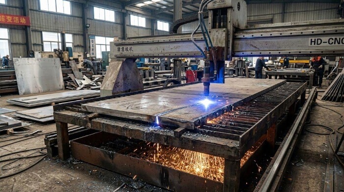
Plasma cutting melts stainless steel using a high-velocity, electrically ionized gas jet. To prevent edge oxidation and minimize dross, industrial fabricators use shielding gases like Nitrogen or H35 (Argon/Hydrogen) instead of compressed air. It rapidly processes mid-to-heavy plates, though precise speed control is essential to minimize the heat-affected zone (HAZ).
This article focuses on the core engineering decisions behind stainless steel plasma cutting, including gas selection, process stability, tolerances, material behavior, and total cost structure. The goal is to connect cutting conditions with real manufacturing outcomes.
The Operational Envelope for Plasma Cutting Stainless Steel
Plasma cutting is not a universal substitute for laser processing. It requires a precise alignment of plate thickness, production volume, and edge tolerance to be economically viable.
Medium-Thickness Optimization
For austenitic stainless steels, high-definition plasma is most effective in the 6mm to 50mm (1/4″ to 2″) thickness range. Below 6mm, fiber laser processing dominates due to superior precision and dross-free edge quality. Beyond 50mm, specialized heavy-duty plasma or waterjet systems are required to manage the extreme thermal loads and material evacuation.
Structural and Heavy Fabrication
When manufacturing flanges, structural gussets, or heavy brackets, dimensional micro-precision is often secondary to mechanical strength and weld readiness. Plasma provides the necessary accuracy for these applications without incurring the exorbitant hourly operating costs of a multi-kilowatt laser system.
Batch Processing and Throughput
Modern mechanized plasma systems excel in mid-to-high volume batch runs. The linear travel speeds surpass those of abrasive waterjet cutting, allowing heavily nested plates to clear the cutting bed rapidly to meet strict mass production schedules.
The Laser-to-Plasma Cost Threshold
As stainless plate thickness exceeds 15mm, the operational cost of fiber laser cutting scales non-linearly. Piercing and severing 20mm 304 or 316 series stainless with a laser demands a 15kW+ oscillator and high-pressure nitrogen assist gas, driving hourly run rates well beyond competitive thresholds for standard structural components.
Production Heuristic: If a 20mm stainless component dictates a tolerance of ±0.2mm, absorbing the high laser operating cost is unavoidable. However, if the functional tolerance is ±1.0mm and the part will undergo downstream welding, high-definition plasma processes the same nested sheet at a substantially lower cost-per-part.
Metallurgical Challenges in Plasma Cutting Stainless Steel
Cutting carbon steel with plasma is heavily assisted by an exothermic oxidation reaction. Stainless steel, however, presents distinct metallurgical and fluid dynamic hurdles. The objective shifts from simply melting the material to strictly managing the melt pool and surface boundary layers.
The Chromium Oxide Barrier
The high chromium content that provides stainless steel its corrosion resistance forms a tough, protective oxide layer. This layer strongly resists the oxidation mechanics utilized in traditional oxy-fuel processing.
To penetrate this barrier, the plasma arc must generate extreme thermal density—often exceeding 20,000°C—to physically melt the alloy, relying entirely on high-velocity assist gases to evacuate the molten material.
Thermal Conductivity and Heat Retention
Austenitic grades (such as 304 and 316) exhibit poor thermal conductivity, transferring heat at approximately 30% the rate of mild steel.
Consequently, heat does not dissipate efficiently through the plate; it concentrates directly at the cut face. This localized heat retention significantly elevates the risk of thermal distortion and warping, particularly when processing high-density nests or thinner gauges.
Melt Pool Viscosity and Dross Accumulation
Molten stainless steel is highly viscous. Unlike the fluid, easily ejected slag generated when cutting carbon steel, the stainless melt pool clings aggressively to the bottom edge of the kerf.
Alloy-Specific Behavior: Viscosity varies by alloy composition. For instance, the molybdenum content in 316 stainless steel increases the viscosity of its molten state compared to 304. Under identical cutting parameters, 316 will exhibit far heavier bottom dross. Establishing a dross-free cutting window requires precise feed rate calibration and highly responsive Torch Height Control (THC).
Managing the Heat-Affected Zone (HAZ)
The combination of intense, localized heat and low thermal conductivity produces a pronounced HAZ along the cut perimeter. This alters the local microstructure, frequently resulting in a hardened, recast layer.
If gas selection is mismanaged—such as utilizing compressed air instead of optimized gas mixtures—the edge will suffer from nitrogen embrittlement. This hardened face will drastically accelerate tool wear, induce chatter, and cause premature insert failure during downstream secondary machining operations like CNC milling, drilling, or tapping.
Gas Selection: Controlling Edge Metallurgy
In high-definition plasma cutting, assist and shield gases are not mere expendables; they actively shape the edge chemistry. The selected gas mixture dictates the oxidation state, surface metallurgy, and whether a cut component proceeds directly to the welding bay or requires intensive mechanical grinding.
Air Plasma
Compressed air is the lowest-cost utility, but it introduces severe operational penalties. Comprising roughly 80% nitrogen and 20% oxygen, air reacts violently with stainless steel to form a heavy, porous oxide scale.
Crucially, this oxide scale acts as a physical barrier during downstream pickling and passivation. Attempting to chemically passivate an air-cut edge severely extends processing times and exhausts pickling acids, driving up hidden chemical costs. Furthermore, TIG or MIG welding directly over this nitrided, oxidized face guarantees severe weld porosity.
Production Rule: Restrict air plasma to non-critical structural components where aesthetics are irrelevant, or where aggressive edge grinding is already factored into the routing sheet.
Nitrogen Cutting
Pure nitrogen eliminates oxygen contamination and heavily reduces the dark oxide crust. It performs effectively on thin-gauge stainless steel (under 6mm). However, nitrogen still induces edge nitriding, leaving a dark gray finish. For highly stressed weldments, this hardened edge typically requires light mechanical grinding to ensure absolute weld pool purity.
F5 Mix Gas
F5 is a specialized blend of 95% nitrogen and 5% hydrogen. The hydrogen acts as a powerful reducing agent, consuming residual oxygen in the kerf.
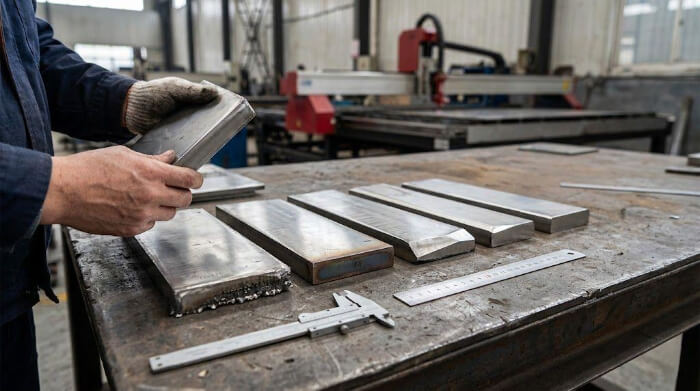
This is the industry standard for medium plates (up to 10mm). It yields a bright, silver, weld-ready edge. While the consumable cost exceeds pure nitrogen, F5 routinely offsets its own expense by eliminating secondary finishing labor.
Argon-Hydrogen (H35)
Composed of 65% Argon and 35% Hydrogen, H35 is mandatory for thick stainless plates (12mm and above). Argon provides critical arc density, while the high hydrogen content generates the extreme thermal energy required to sever thick cross-sections.
H35 produces a dross-free edge with a slight golden hue. The Economic Trade-off: H35 carries the highest gas cost per hour. However, when processing 25mm plate, bypassing the manual labor required to grind a thick oxidized edge makes the gas investment highly profitable.
Diagnosing Edge Quality and Process Variables
When edge quality drops, operators frequently blame the gantry. However, poor cuts usually stem from unstable fluid dynamics and parameter drift rather than mechanical limitations.
Dross Accumulation
The high viscosity of molten stainless makes identifying the optimal “dross-free window” challenging. Low-speed dross manifests as hard, globular deposits on the bottom edge that require heavy grinding. High-speed dross forms a thin, easily chipped rollover lip. If thick dross is fusing to the bottom of the plate, the feed rate is too slow or the arc voltage (torch height) is set too high.
Unplanned Oxidation
If components cut with F5 or Nitrogen exhibit dark oxidation, atmospheric contamination is occurring. Rather than adjusting CNC parameters, inspect the gas delivery infrastructure. Look for micro-leaks, verify dynamic flow rates at the regulators, and ensure shield gas pressure is sufficient to evacuate ambient air from the arc zone.
Cut Bevel Dynamics
The plasma arc resembles a teardrop, and the swirling gas dynamics cause one side of the kerf to cut straighter than the other. Ensure your CAM software programs outer perimeters clockwise and inner features counter-clockwise. Even with perfectly dialed parameters, expect an inherent 1° to 3° edge bevel.
Piercing Blowback
Piercing thick stainless generates violent molten blowback. If the standoff distance is incorrect, spatter will fuse to the shield cap, instantly ruining consumables. Modern controllers mitigate this using a dynamic pierce cycle: firing at a high standoff, allowing penetration, and then dropping to the cut height.
Production Rule: Maximum pierce capacity is generally 50% of the edge-start capacity. Never attempt a center-pierce on a 40mm plate if the equipment is only rated for 40mm edge-starts.
Torch Height Control (THC)
THC utilizes arc voltage feedback to maintain a consistent consumable-to-plate distance. As electrodes and nozzles wear, arc voltage fluctuates. A sluggish THC allows the torch to drift. Just a 1mm deviation in torch height will alter the edge bevel and trigger severe low-speed dross.
DFM Limitations for Plasma-Cut Stainless
Plasma cutting possesses rigid geometric limits. Forcing a high-definition plasma system to hold laser-grade micro-tolerances yields high scrap rates and stalled production. Design for Manufacturing (DFM) must respect the physical constraints of the plasma arc.
Small Holes and Tapping Failures
Proprietary “True Hole” algorithms are highly effective on carbon steel but struggle against the fluid dynamics and arc lag of stainless steel. Small plasma-cut holes in austenitic grades consistently develop a bell-mouth profile and a work-hardened, tapered bottom.
Attempting to run a CNC tap directly into this nitrided, tapered hole will fracture the tap. Extracting a snapped tap from 316 stainless requires EDM processing, instantly wiping out batch profitability. For tapped features, pierce the hole undersized and use a mechanical drill or reamer to achieve the final pre-tap diameter.
The Shop-Floor DFM Checklist
To prevent thermal distortion, feature collapse, and scrap, evaluate engineering prints against these physical realities:
- Minimum Hole Diameter: Must be ≥ 1.5x material thickness. (e.g., Do not attempt to plasma-cut a 20mm hole in a 20mm plate; mark the center with the torch and drill it).
- Minimum Web Spacing: Solid material remaining between adjacent kerf lines must be ≥ 1.0x to 1.5x material thickness. Narrower webs will melt away under the extreme thermal load.
- Angularity Allowance: Assume a standard cut bevel of 1° to 3° (ISO 9013 Range 3/4). Accommodate this dimensional variance in mating assemblies, welding fixtures, and joint designs.
The Impact on Secondary Processing and Welding
A critical error in production routing is viewing the plasma cell as the final operation. The metallurgical state of the cut face directly dictates the labor burden, tool wear, and failure rates in the downstream welding and finishing bays.
The Refractory Oxide Layer
Depending on the assist gas, plasma processing leaves a refractory chromium oxide scale on the cut face. This scale possesses a higher melting point than the base alloy. Striking a welding arc directly over this layer traps these oxides within the weld pool, leading to severe slag inclusions and structural failure.
Nitride Contamination and Weld Porosity
Utilizing compressed air or pure nitrogen forces nitrogen gas into the molten kerf, forming a localized nitrided layer. During subsequent TIG or MIG welding, the thermal energy releases this trapped nitrogen. As the gas attempts to escape the solidifying weld pool, it generates severe weld porosity (often identifiable as “wormholing” during radiographic NDT).
The Mechanical Grinding Requirement
Standard Routing Procedure: Air- or nitrogen-cut edges are unfit for structural welding without mechanical prep. Operators must grind away 0.5mm to 1.0mm of the cut face to expose uncontaminated base metal. When quoting a job, this manual grinding time—which frequently exceeds the actual CNC cutting cycle—must be factored into the per-part cost baseline.
Coating and Paint Preparation
If the routing includes powder coating or industrial painting, edge metallurgy remains critical. Coatings adhere to the oxide scale, not the steel substrate. Under thermal expansion or mechanical flex in the field, the brittle oxide layer will spall off, taking the coating with it. Edges mandate mechanical deburring, wire brushing, or media blasting to achieve the required surface profile for permanent adhesion.
Material Behavior Across Gauges and Alloys
The thermal dynamics of the plasma arc shift radically as plate thickness increases. Parameters optimized for one thickness will induce catastrophic failure on another.
Thin Gauge Sheets (Under 6mm)
High-definition plasma injects massive thermal energy, inducing severe thermal distortion and warping in thin sheet metal. Unless running at maximum feed rates over a water table for rapid quenching, fiber laser processing is the undisputed requirement for gauges under 6mm.
Medium Plates (6mm to 20mm)
This is the operational sweet spot for sheet metal plasma processing. The material mass is sufficient to act as a heat sink without severe warping. Utilizing an F5 gas mixture yields an optimal balance of rapid feed rates, minimal edge angularity, and a clean surface finish.
Thick Plate Stability (Over 20mm)
Beyond 20mm, the arc column must be significantly longer and hotter, mandating Argon-Hydrogen (H35) gas.
The Piercing Bottleneck: The primary shop-floor risk is pierce blowout. Molten blowback will destroy the shield and nozzle instantly. Processing thick plates demands generous lead-ins and precise dynamic piercing routines. Edge angularity also scales with thickness, frequently necessitating secondary CNC milling if the profile must mate flush in an assembly.
Phase Imbalance in Duplex Stainless
Unlike forgiving 300-series austenitic grades, Duplex stainless steels require strict thermal management. Specified for harsh marine and chemical environments, Duplex relies on a precise 50/50 microscopic phase balance of austenite and ferrite for its corrosion resistance.
The extreme heat input of the plasma arc can destroy this phase balance within the Heat Affected Zone (HAZ), leaving the edge susceptible to rapid pitting corrosion. Processing duplex requires tightly optimized feed rates and rapid quenching to limit the material’s time-at-temperature.
Total Cost of Ownership (TCO): Plasma vs. Fiber Laser
When routing a medium-to-thick stainless mass production run, evaluating cutting speeds (IPM) in isolation is a flawed metric. The only calculation that dictates profitability is the Total Cost of Ownership (TCO) per usable part.
Capital Depreciation
The capital expenditure delta is substantial. A high-definition plasma cell capable of processing 25mm plate ranges from $100,000 to $150,000. A high-kilowatt fiber laser rated for the same production throughput easily exceeds $800,000. Consequently, the machine depreciation burden assigned to each part is drastically lower with plasma.
Operating Draw
High-power lasers require massive electrical draw and high-pressure nitrogen assist gas, which depletes rapidly on thick plates. While specialized plasma mixtures like H35 carry a premium, the aggregate hourly operating rate of a plasma table remains significantly lower than a heavy-plate laser system.
Consumable Burn Rate
This is the primary operational penalty for plasma. The intense thermal load and molten blowback aggressively degrade nozzles, electrodes, swirl rings, and shields. A high-volume shift may require multiple consumable changeovers, whereas laser optics and nozzles exhibit much longer lifespans.
Secondary Labor
The Hidden Factory Math: If a laser yields a dross-free part, but an air-plasma cut demands 15 minutes of manual grinding to remove nitrides, the plasma process is ultimately more expensive.
On a batch of 1,000 structural brackets, that 15 minutes equates to 250 hours of pure manual labor applied solely to edge prep. This highlights exactly why upgrading to premium H35 gas to achieve a weld-ready plasma edge is a highly profitable strategy—it eliminates the crushing cost of secondary finishing labor.
Rework and Material Scrap
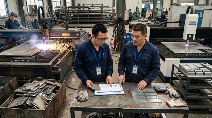
Scrapping a 20mm stainless plate due to a torch collision or loss of arc destroys batch margins. Because plasma relies heavily on fluid dynamics and consumable wear compensation, the process demands skilled operators to maintain strict process control and keep scrap rates at zero.
Conclusion
Plasma cutting stainless steel is a precise metallurgical operation, not a rudimentary material separation tactic. Edge quality is a direct function of assist gas chemistry and process stability. Downstream weld integrity relies on mitigating oxidation and controlling the HAZ. True profitability is determined by minimizing secondary rework, finishing labor, and scrap.
Engineering decisions must be anchored in functional tolerances and a realistic evaluation of the entire routing cost.
At TZR, we don’t just separate metal; we engineer the entire manufacturing lifecycle. With 10+ years of expertise spanning rapid prototyping to mass CNC and sheet metal production, we ensure your components arrive ready for the welding bay—not the grinding station.
Protect your batch profitability and component integrity. Upload your CAD files today, and let our seasoned engineers handle the fluid dynamics, thermal management, and strict tolerances of your next demanding project.
FAQ
Can you plasma cut stainless steel with compressed air?
Yes, but the edge quality will suffer. The oxygen in the air creates a thick, dark oxide scale, while the nitrogen causes edge nitriding. If you weld directly over an air-cut edge, you will get severe weld porosity. Use air only if post-cut grinding is already scheduled.
What are the health hazards of plasma cutting stainless steel?
The primary danger is Hexavalent Chromium [Cr(VI)]. The intense heat vaporizes the chromium in stainless steel into a highly toxic, carcinogenic fume. You must use a water table to quench the particles or a high-velocity downdraft table with industrial HEPA filtration.
Can you plasma cut polished or coated stainless steel?
Yes. However, if the sheet has a PVC protective film, you must use pure nitrogen as both the plasma and shield gas to prevent the plastic from catching fire and ruining the finish. Also, ensure the ground clamp is attached to a bare metal section to complete the circuit.
What metals can a plasma cutter NOT cut?
Plasma cutting requires an electrical arc between the torch and the workpiece. Therefore, it cannot cut non-conductive materials like plastics, wood, or glass. It can easily cut any conductive metal, including carbon steel, stainless steel, aluminum, and copper.