
Spot welding is a resistance welding process used to fuse overlapping sheet metals at specific contact points without filler material. By applying pressure and high electrical current through copper electrodes, it creates strong, localized joint nuggets, offering an efficient solution for high-volume manufacturing.
Transitioning a project from a prototype into mass manufacturing usually highlights these variables. Drawing on over a decade of sheet metal fabrication experience, this article explains spot welding from a practical production standpoint. It provides clear guidelines to help engineers design more manufacturable parts.
How Spot Welding Works in Real Production?
Spot welding is more than just clamping metal together. Understanding this physical sequence helps engineers anticipate manufacturing challenges before mass production begins.
Working Principle
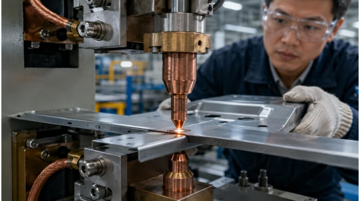
Spot welding operates on the principle of electrical resistance. Two copper alloy electrodes pinch the sheet metal pieces together under specific mechanical pressure. A low-voltage, high-amperage current is then passed through the electrodes.
Because the interface between the two metal sheets presents the highest electrical resistance in the circuit, the current generates localized heat. This thermal generation is governed by Joule’s law (Q = I²Rt). The heat quickly melts the metal at the contact point without the need for any filler material.
Weld Nugget
Once the current stops, the molten metal cools and solidifies under continuous pressure. This forms a weld nugget, which is the actual structural bond between the sheets. In general manufacturing practice, the target nugget diameter is often calculated as d = 5√t, where t is the thickness of the thinner sheet in millimeters.
A properly formed nugget is fully internal, leaving only minor indentations on the outer surfaces. If the nugget is too small, the joint will be weak and fail under load. If the current is too high and the molten core breaches the surface, it causes spatter. This expels metal and creates a rough surface that often requires costly manual grinding.
Weld Cycle
A reliable weld requires strict timing. The machine executes a specific four-step sequence for every spot. It starts with the Squeeze stage, bringing the electrodes down to build the required physical force before power is applied. Next is the Weld stage, where the precise current is delivered to generate heat.
The current then cuts off, entering the Hold stage. This phase maintains mechanical pressure while the nugget cools and solidifies to prevent internal micro-cracking. Finally, the Off stage releases the electrodes so the operator or robot can move the part to the next position.
Suitable Applications
This process is usually used for lap joints, where two flat sheet surfaces overlap. It works well for sheet metal thicknesses ranging from 0.5 mm to roughly 3.0 mm. It is commonly specified for electrical enclosures, internal brackets, chassis, and assemblies requiring high structural rigidity.
Because the cycle time per spot is a fraction of a second, the process scales very well. It is highly compatible with robotic automation. Automating the weld cycles ensures consistency across thousands of parts and significantly drives down piece-part costs in high-volume production.
Material Limits That Affect Weld Quality
Not all sheet metals behave the same under intense heat and pressure. Selecting the right material directly impacts weld strength, cosmetic finish, and equipment maintenance.
Mild Steel
Low carbon steel (mild steel) is generally considered the baseline material for spot welding. It has an ideal balance of electrical resistance and thermal conductivity. This means it heats up efficiently exactly at the joint and cools at a predictable rate.
As a result, mild steel is highly forgiving in production. It requires standard equipment settings, minimizes electrode wear, and consistently produces strong, uniform welds without demanding specialized controls.
Stainless Steel
Stainless steel has a higher electrical resistance and lower thermal conductivity compared to mild steel. Heat builds up faster and stays concentrated in the weld area much longer. If not controlled, this excess heat can cause severe surface discoloration, warping, or degradation of the metal’s anti-corrosion properties.
To manage this, operators usually apply lower welding currents and shorter weld times. This is often paired with higher electrode force to contain the molten core. Production setups frequently use water-cooled electrodes to pull heat away from the surface as quickly as possible.
Galvanized Steel
Welding galvanized sheet metal introduces specific maintenance challenges on the factory floor. The protective zinc coating has a much lower melting point than the underlying steel. During welding, this molten zinc tends to alloy with the copper electrodes, leading to pitting and the electrodes physically sticking to the workpiece.
To achieve consistent penetration through the zinc layer, the process requires higher welding currents. Modern equipment often uses a stepper function in the controller. This feature automatically and gradually increases the current as the electrode degrades, extending the time between mandatory tip dressing.
Aluminum
Aluminum is highly conductive to both electricity and heat. To generate enough localized heat before it dissipates into the surrounding metal, the process demands extremely high currents. This often means two to three times the amperage required for steel, delivered in a very brief burst.
Welding aluminum consistently at scale usually requires more advanced Mid-Frequency Direct Current (MFDC) inverter welders to deliver these rapid, precise power spikes. Additionally, aluminum forms a tough surface oxide layer with uneven electrical resistance, meaning strict pre-weld surface cleaning is often required for critical components.
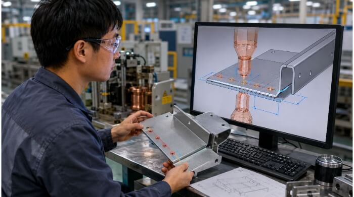
DFM Rules for Better Spot Welded Parts
A reliable weld starts in the CAD model, not on the factory floor. Following these specific design guidelines prevents costly rework and ensures automation compatibility.
Lap Width
When designing lap joints, the overlap area must be wide enough to fully contain the molten weld core. If the weld is placed too close to the edge, the molten metal bursts out from the side, a defect known as edge expulsion. Edge expulsion leaves sharp burrs that require manual grinding and results in a severely weakened joint.
Furthermore, a narrow lap leaves no room for the natural positional tolerance of robotic welders. If the robot drifts by even a millimeter, the weld fails, causing the scrap rate to spike. As a general manufacturing rule, the minimum lap width should be at least two times the required weld nugget diameter (usually 12 mm to 15 mm for standard thin sheets).
Weld Pitch
Weld pitch refers to the distance between the centers of two adjacent spot welds. Designers sometimes place welds extremely close together, assuming more spots equal a stronger part. In reality, placing welds too close causes a serious problem called the “shunting effect.”
When a new weld is placed too close to an existing one, the electrical current takes the path of least resistance. It flows through the already finished weld rather than passing through the two separate sheets. The new spot receives too little heat, resulting in a weak or failed connection. A safe engineering guideline is to keep the minimum weld pitch at least 10 times the material thickness.
Electrode Access
Spot welding machines use large, rigid copper arms and bulky electrode holders. A frequent DFM failure is designing deep U-channels, narrow boxes, or tight corners where the welding gun simply cannot reach or close properly. If the electrodes cannot physically access the joint at a 90-degree angle, the standard process fails.
Poor access forces the factory to machine custom offset electrodes. This adds unnecessary tooling costs and lead time to the project. If custom tooling is not possible, the design will require alternative methods like blind riveting or manual TIG welding, which immediately increases the piece-part cost. Always account for tooling clearance in 3D CAD models.
Bend Clearance
The welding electrodes need a completely flat surface to apply even, consistent pressure. If a spot weld is positioned too close to a bent edge, the electrode will sit unevenly on the bend radius.
When the machine applies force, the electrode will slip or crush the bend. This deforms the cosmetic appearance of the part and creates an unbalanced electrical contact, leading to a poor weld. To prevent this, the center of the spot weld should be placed at least one full electrode diameter away from the tangent line of the bend.
Process Factors That Control the Weld Result
Perfecting a spot weld requires carefully balancing multiple machine variables. Dialing in these core parameters is the only way to guarantee consistent, high-volume production quality.
Welding Current
Welding current is the most critical variable in generating heat, as heat increases with the square of the current. The amperage must be tuned specifically to the material type and thickness. If the current is too low, the metal will not melt sufficiently, leading to a cold weld that easily breaks under stress.
Conversely, if the current is too high, it will burn through the metal, cause heavy spatter, and leave deep, unacceptable indentations on the part surface. Because of these tight margins, determining the exact current requires the factory to perform destructive teardown tests to establish a formal Weld Schedule before production begins.
Electrode Force
Mechanical pressure from the electrodes serves two purposes: it forces the sheets together to close any air gaps, and it contains the molten metal nugget while it forms.
If the electrode force is too low, the contact resistance at the surface becomes too high. This causes the surface to burn and expel molten sparks. Conversely, if the pressure is too high, it crushes the material and drops the electrical resistance too much. The current simply passes through without generating enough internal heat, leaving a weak joint.
Weld Time
Weld time dictates how long the current flows through the joint. In traditional AC machines, this is measured in line cycles (e.g., 1/50th of a second), while modern inverters measure it in milliseconds.
The goal is to apply current just long enough to grow the nugget to the target diameter. Extending the weld time past this point does not make the weld stronger. It only increases the heat-affected zone (HAZ), causes the sheet metal to warp, and accelerates the degradation of the copper electrodes.
Electrode Wear
In a high-volume production environment, copper electrode tips repeatedly endure extreme heat and heavy mechanical pounding. Over time, the tips “mushroom,” meaning they flatten out and their surface area increases. When the tip area increases, the electrical current spreads over a larger space, lowering the current density.
This drop in density will eventually cause weak welds if the machine settings remain static. To counteract this, factories depend on strict tip dressing routines (machining the copper back to its original profile). However, frequent tip dressing means machine downtime. This is why material selection and tip geometry directly impact the overall efficiency and final piece-part price in high-volume runs.
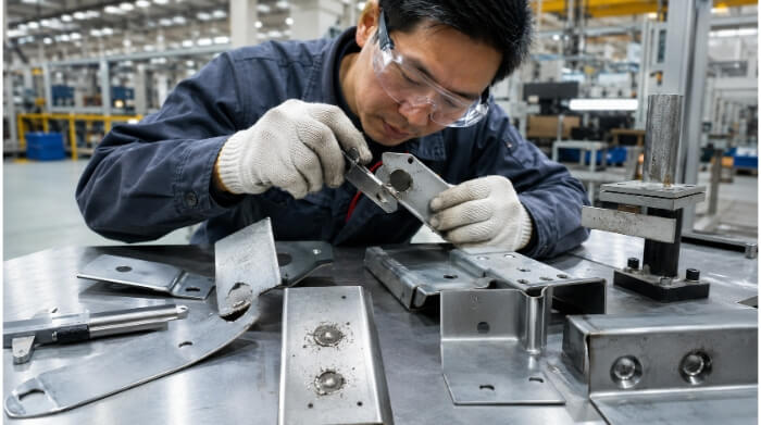
Common Defects and Quality Checks
Even the best machine setups can drift, and visual inspections rarely tell the whole story. Factories rely on strict destructive testing to catch these hidden flaws.
Weak Welds
A weak weld, often called a cold weld, occurs when the metal pieces do not fuse properly. This is one of the most dangerous defects because the part often looks perfectly normal from the outside.
Cold welds are typically caused by insufficient current, excessively high electrode pressure (which drops the resistance too low to generate heat), or the shunting effect. Because visual inspection cannot reliably detect a cold weld, factories must rely on strict process controls and routine destructive testing to guarantee joint strength.
Spatter
Spatter happens when molten metal bursts out of the weld zone during the heating cycle. It can occur between the two sheets (internal spatter) or at the surface where the electrode touches the metal (surface spatter).
This defect is usually driven by the current being too high, the electrode force being too low, or the weld being placed too close to the material edge. Aside from indicating an unstable weld process, spatter leaves sharp burrs on the part. This almost always forces the factory to add a secondary manual grinding operation, driving up labor costs.
Deep Indentation
Electrodes naturally leave a slight depression on the surface of the metal. However, an indentation is considered a defect if its depth exceeds 25% of the sheet thickness. Deep indentations reduce the cross-sectional thickness of the parent metal, creating a weak point that is prone to fatigue failure.
This issue is typically caused by overheating or poorly maintained electrode tips. If a part requires a flawless cosmetic finish on one side (the “show side”), the factory can mitigate indentation by using a standard pointed electrode on the hidden side and a larger, flat copper block on the visible side to distribute the pressure.
Destructive Testing: Peel and Chisel Tests
Because visual inspection is inadequate, factories rely on destructive testing for quality assurance. During a production run, sample parts are subjected to a peel test, where the welded sheets are physically ripped apart. In a passing test, the weld nugget must remain completely intact and tear a hole out of the surrounding parent metal.
This is known in the industry as pulling a “tear button.” If the sheets break apart cleanly at the flat interface, it is an interfacial fracture—a failed weld that triggers an immediate halt to production.
For large assemblies where full peeling is impossible or too wasteful, operators use a chisel test. By driving a wedge between the sheets near the weld, they can verify that the nugget holds strong under stress without completely destroying the entire part.
Choosing Spot Welding or Another Joining Method
Spot welding is highly efficient, but it isn’t always the perfect fit. Evaluating alternative methods helps you balance structural needs, aesthetic goals, and project budgets.
Blind Riveting
Blind riveting is the standard alternative when a part design does not allow the two-sided access required by spot welding electrodes. It is also the preferred method for joining dissimilar metals, such as fastening an aluminum bracket to a steel chassis—though designers must account for galvanic corrosion between the differing materials over time.
While riveting avoids heat distortion and metallurgical issues, it introduces different costs. Every joint requires a physical fastener, adding to the BOM (Bill of Materials) cost and the overall weight of the assembly. Additionally, riveting often requires tighter hole-alignment tolerances between the mating parts.
Laser Spot Welding
Laser spot welding is a modern alternative that requires access to only one side of the assembly. It uses a highly focused laser beam to penetrate and fuse the overlapping sheets. The process generates a remarkably small heat-affected zone (HAZ), eliminating the heavy distortion associated with traditional resistance welding.
While it offers superior aesthetics and excels at welding challenging materials like aluminum and copper, laser welding has strict limitations. It requires near-zero gap tolerances between the sheets; if the parts do not fit together perfectly flat, the laser will simply burn a hole through the top layer. Furthermore, the capital equipment cost for laser welding is significantly higher, which usually translates to a higher hourly machine rate.
Conclusion
Resistance spot welding remains a cornerstone of sheet metal fabrication. It is incredibly fast, eliminates the need for consumables, and becomes highly cost-effective at scale. However, maximizing its benefits requires a strong understanding of material behaviors, strict adherence to DFM guidelines, and rigorous shop-floor quality controls.
When transitioning a sheet metal project from prototype to high-volume manufacturing, having a fabrication partner who understands these variables is critical. At TZR, our engineering team brings over 10 years of sheet metal processing experience to the factory floor.
If you are evaluating a part design for spot welding, or comparing it against riveting and laser welding, contact our team for an objective DFM review and mass production manufacturing support.
FAQs
Can you spot weld different thicknesses of metal together?
Yes, it is common to spot weld varying thicknesses. However, a general manufacturing guideline is to keep the thickness ratio below 3:1. If the difference is too extreme, the thinner sheet may melt or burn through before the thicker sheet reaches the proper welding temperature.
Does spot welding require shielding gas?
No. Unlike MIG or TIG welding, resistance spot welding does not require argon or carbon dioxide shielding gases. The process relies entirely on electrical resistance to generate internal heat, and the mechanical pressure from the electrodes keeps oxygen out of the weld zone while the metal fuses.
Can you spot weld painted or anodized metal?
No. Spot welding requires electrical conductivity between the electrodes and the metal sheets. Paint, powder coating, and heavy anodized layers act as insulators and will prevent the current from flowing. The metal must be bare, though highly conductive thin coatings like zinc (galvanized steel) can be welded with modified machine parameters.