
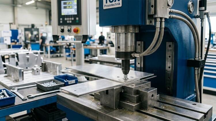
Press riveting is a cold-forming process that creates a permanent mechanical lock between a fastener and sheet metal without using heat. In this process, pressure drives a rivet or fastener into a pre-drilled hole to form a strong, lasting connection. It is widely used to produce repeatable joints while reducing distortion, secondary finishing, and assembly time.
The value of press riveting goes beyond the machine itself. Teams need to know how to design the joint, when to choose it over welding, and how it affects total assembly cost from prototyping to mass production.
This guide explains how the joint gains strength and which design rules matter most. It also looks at tooling limits, common defects, and the point at which the process makes economic sense in manufacturing.
Where Press Riveting Fits in Sheet Metal Assembly?
Press riveting works best when a joint needs strength, speed, and no heat distortion. The points below show where it performs well and where another method may be better.
Cold mechanical joining
Unlike thermal processes, press riveting relies entirely on mechanical force. A specialized fastener is pressed into a pre-punched or laser-cut hole. Under pressure, the base sheet metal cold-flows into the fastener’s designed geometry (usually an undercut or groove).
This creates a solid, vibration-resistant interlock. Because the process occurs at room temperature, it eliminates the risks of thermal distortion, material degradation, and metallurgical changes in the base metal.
Suitable load and assembly conditions
Press riveting is the standard choice when you need to add strong, load-bearing threads or attachment points to sheet metal that is too thin to be safely tapped. Typically, this applies to materials less than 2.5mm thick.
It is also highly effective in environments subject to vibration. This makes it a staple joining method in server chassis, electrical enclosures, automotive sub-assemblies, and aerospace brackets.
When spot welding adds extra cost
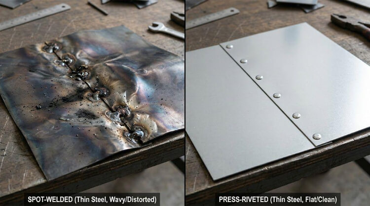
While spot welding or projection welding might seem cheaper on a per-consumable basis, the hidden costs often ruin unit economics. Welding thin-gauge metals (such as 1.0mm aluminum or stainless steel) frequently causes heat warping, requiring manual straightening.
Furthermore, welding burns off surface coatings. If you weld, you must grind the surface flat and perform plating or powder coating after assembly. Press riveting allows you to use pre-plated, pre-painted, or anodized sheet metal, eliminating the need for secondary surface finishing.
Cases that need another method
Press riveting is not a universal fix. If your design requires a perfectly flush surface on both sides of the sheet without counter-machining, this process will not work.
Additionally, it is heavily restricted by access to tooling. If the rivet location is deep inside a narrow U-channel or a surprise box, the press machine’s C-frame will physically interfere with the part. Finally, if the assembly requires frequent teardowns or non-destructive maintenance, removable mechanical fasteners are the required alternative.
What Builds Joint Strength?
Joint strength does not come from pressing force alone. It depends on material flow, hole fit, and how the fastener locks into the sheet.
Material flow and mechanical locking
The structural integrity of a press-riveted joint is not determined by the fastener alone, but by how effectively the base material moves. When the press ram applies axial force, the harder fastener acts as a die.
It displaces the softer sheet metal, forcing it to yield and flow plastically into the fastener’s annular recess (the undercut). This trapped volume of metal is what creates the permanent mechanical lock.
Hole filling and backside forming
For maximum strength, the displaced sheet metal must fill the fastener’s undercut. If the material does not flow sufficiently, the joint will fail under load.
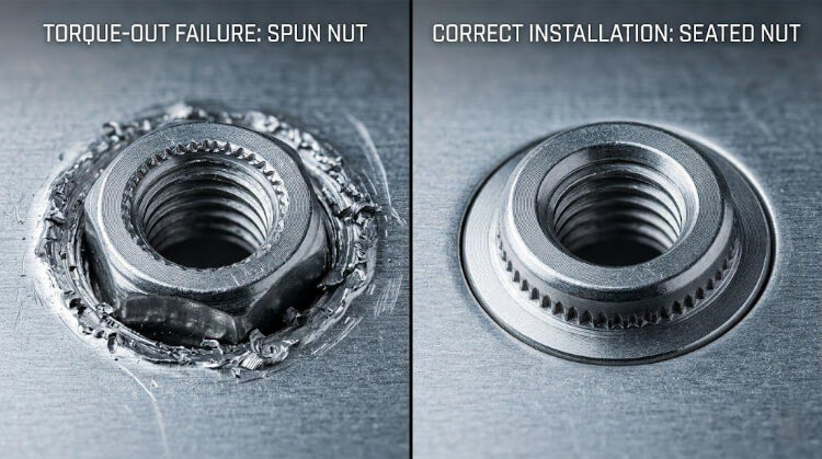
A properly engineered press-rivet joint will look clean on both sides. On the installation side, the fastener head is embedded flush (or slightly sub-flush) with the sheet surface. On the reverse (blind) side, the sheet metal remains flat, without cracking, bulging, or excessive deformation.
Pull-out and torque resistance
Engineers must evaluate joint strength across two specific vectors: pull-out (push-through) and torque-out.
- Pull-out resistance is dictated by the volume of sheet metal that successfully flows into the undercut groove.
- Torque-out resistance is generated by the knurled ring, splines, or hex shape beneath the fastener’s head. As the fastener is pressed in, these teeth bite into the sheet metal, preventing the fastener from spinning when a mating screw is tightened.
Material hardness and sheet thickness
The most critical rule in press riveting is the hardness differential. If you attempt to press a standard 300-series stainless steel rivet into a 300-series stainless steel sheet, the fastener will crush before the sheet metal flows.
Additionally, sheet thickness dictates the choice of hardware. The sheet must be thick enough to provide an adequate volume of material to flow into the undercut.
💡 Engineering Rule of Thumb: > Hardness Gap: The fastener must be at least 20 HRB harder than the base sheet metal.
- Minimum Sheet Thickness: Typically 0.8mm (0.030″) for standard self-clinching hardware. Going thinner requires specialized micro-fasteners.
What Engineers Should Confirm in the Design?
Many press riveting problems begin in the drawing stage. Early design checks help avoid weak joints, tooling interference, and costly changes later.
Pilot hole tolerance and sheet thickness
A press-riveted joint is only as strong as its pilot hole. Because the process relies on precise material displacement, the hole must be perfectly sized. If the hole is oversized, there will not be enough sheet metal to flow into the fastener’s undercut, severely reducing pull-out strength.
If the hole is undersized, the required press force spikes. This causes the sheet metal to warp, buckle, or even damage the installation tooling. Furthermore, the hole must be created cleanly. While modern fiber lasers are acceptable, CNC punched holes are often preferred because they do not create a heat-affected zone (HAZ) that hardens the hole edge.
💡 Engineering Rule of Thumb: > Hole Tolerance: Standard pilot holes for self-clinching fasteners require a tight tolerance, typically +0.08mm / -0.00mm (+0.003″ / -0.000″).
- Never Deburr: Do not chamfer or heavily deburr the edge of the pilot hole. You need those sharp edges to provide the material volume that flows into the fastener.
Edge distance and hole spacing
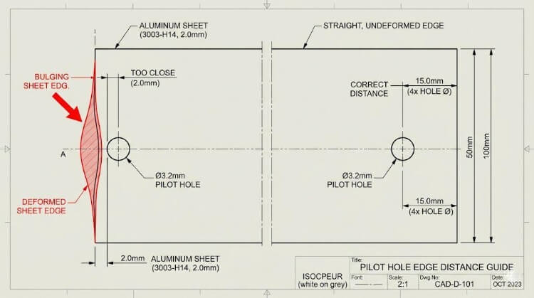
When the fastener is pressed in, the displaced sheet metal expands outward. If the pilot hole is placed too close to the edge of the sheet, this material expansion will push the edge outward, causing it to bulge or tear.
Similarly, if multiple fasteners are placed too close together, the overlapping stress zones will cause the sheet metal to warp permanently. You must consult the specific fastener manufacturer’s catalog for the Minimum Centerline-to-Edge distance.
Bends, channels, and tooling clearance
Many press-riveting failures occur not because of bad hardware, but because of physical interference. The C-frame press requires a hardened punch on top and an anvil on the bottom. If you place a rivet too close to a 90-degree bend, the anvil cannot sit flat against the sheet.
When the sheet sits at an angle, the fastener is driven in crooked, ruining the joint. Furthermore, if you are designing a deep U-channel or a server chassis interior, you must ensure that the press machine’s throat depth can reach the hole location.
💡 Engineering Rule of Thumb: > Bend Clearance: The distance from the center of the pilot hole to the inside edge of a bend should be at least 1.5 times the fastener’s outside diameter plus the bend radius.
Dissimilar metals and corrosion risk
Press riveting allows you to join dissimilar metals (e.g., carbon-steel fasteners to aluminum sheets) without the metallurgical nightmares of welding. However, it introduces a different threat: galvanic corrosion.
When a noble metal (such as a stainless steel fastener) is pressed into an active metal (such as an aluminum sheet), and the assembly is exposed to moisture, the aluminum will corrode rapidly. To prevent this, engineers must specify the correct surface plating on the fastener. For example, using a zinc-plated carbon-steel fastener in an aluminum chassis serves as a sacrificial barrier, protecting the base metal.
What Keeps the Process Stable in Production?
A successful sample does not always lead to stable output. Stable production depends on setup control, consistent force, and clear inspection points.
Set up consistency and process window
Transitioning a perfect CAD design to the shop floor requires defining a strict process window. Press riveting is not simply “smashing a rivet until it stops.” It is a precise balance of force and displacement.
If the setup technician uses too much force, the sheet metal will crush and deform. If they use too little, the knurled teeth won’t bite, resulting in spinning hardware. The process window—the exact tonnage required to seat the fastener flush—must be established during the first article inspection and locked in for the entire batch.
Fastener and tooling match
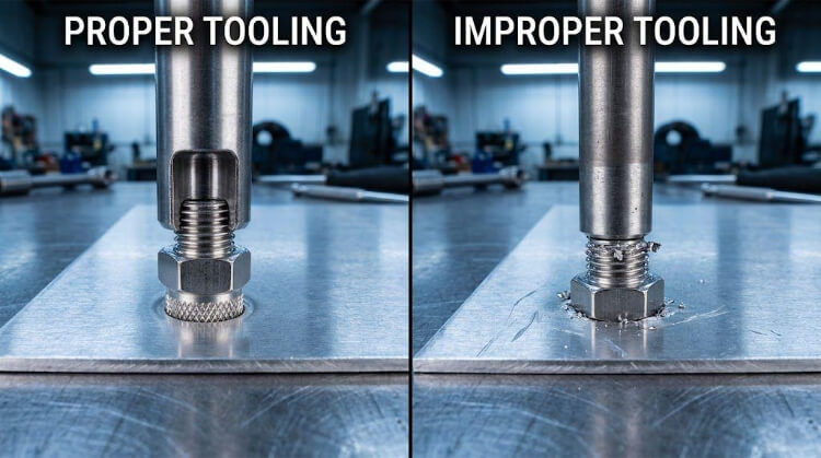
Each press fastener type requires a specific combination of punch (top tool) and anvil (bottom tool). You cannot use a universal flat anvil for everything.
For example, a flush-head nut requires a flat punch and a flat anvil. However, a self-clinching standoff requires a punch with a recessed cavity to prevent the threaded barrel from being crushed. Using the wrong tooling will either destroy the fastener’s threads or leave terrible cosmetic marks on the blind side of the sheet metal.
Press force, dwell, and part support
Force is only part of the equation; time is the other. Cold-flowing sheet metal is a plastic deformation process that takes a fraction of a second to complete. Advanced press machines use a programmed “dwell time” at the bottom of the stroke.
This millisecond pause allows the metal to fully flow into the undercut and stabilize before the pressure is released. Additionally, the operator must ensure the sheet metal is fully supported and flat against the anvil before cycling the machine.
Force monitoring and inspection checks
In high-volume production, relying solely on visual inspection is a massive risk. A fastener might look flush but still fail a torque test.
Modern press machines utilize load cells and linear encoders to monitor the force-over-distance curve of every single press cycle. If a hole is too big, the force will drop too early, and the machine will flag the part as defective.
💡 Engineering Rule of Thumb for QC: > Non-Destructive Testing: Verify that the fastener head is flush to within 0.05mm of the sheet surface.
- Destructive Testing: Pull out 1 part per 500 from the batch to perform a physical push-out and torque-out test using a calibrated torque wrench, comparing the yield against the manufacturer’s spec sheet.
What Causes Common Press Riveting Defects?
When a press-riveted joint fails, it is rarely a mystery. It is almost always a failure of process control, tooling alignment, or dimensional tolerances. Below is the troubleshooting guide for the four most common shop-floor failures.
Joint rotation and low torque retention
The Defect: The fastener head looks flush, but when the assembly line operator drives a screw into the nut (or tightens a nut onto the stud), the rivet spins in the sheet metal.
- Root Cause 1: Insufficient press force. The knurled teeth under the head never fully bit into the base material.
- Root Cause 2: The pilot hole was punched at the maximum upper tolerance, leaving too little sheet metal to flow into the splines.
- Root Cause 3: The sheet metal was work-hardened during a previous forming step, making it too hard for the fastener’s teeth to penetrate.
- The Fix: Verify the hole size with a pin gauge. Increase press tonnage slightly. Check the hardness gap between the specific sheet batch and the fastener.
Incomplete setting and low pull-out strength
The Defect: The fastener pops out when axial load is applied, or the head sits visibly proud (above) the sheet metal surface.
- Root Cause 1: The anvil (bottom tool) counter-bore is too large, allowing the sheet metal to flow downward away from the joint instead of inward into the fastener’s undercut.
- Root Cause 2: The press stroke was too fast, lacking the required “dwell time” to allow plastic deformation to complete.
- The Fix: Replace the anvil with one that matches the manufacturer-specified dimensions. Add a 0.5-second dwell time to the press cycle at bottom-dead-center.
Surface marks and local sheet deformation
The Defect: The blind side of the sheet metal has a heavy ring stamped into it, or the sheet is warped and no longer flat around the fastener.
- Root Cause 1: Over-pressing. The operator applied too much tonnage trying to force a flush set, driving the anvil deep into the blind side.
- Root Cause 2: Tool misalignment. The punch and anvil are not perfectly concentric, causing the fastener to be pushed in at an angle.
- The Fix: Re-align the C-frame tooling axes. Drop the pressure and verify the fastener length matches the sheet thickness.
Batch-to-batch process variation
The Defect: The process runs perfectly on a Monday but yields a 10% failure rate on a Thursday using the same machine settings.
- Root Cause: Standard sheet metal thickness varies. A “1.5mm” steel sheet from the mill might actually measure 1.42mm in one batch and 1.55mm in the next. If the press is set to a fixed mechanical stroke (distance), rather than a fixed force (tonnage), the pressure applied to the joint will fluctuate wildly.
- The Fix: Upgrade to hydraulic or servo-electric presses that stop based on a force-curve logic, rather than a hard mechanical stop.
How to Compare Methods and Control Total Cost?
Procurement teams often make the mistake of comparing joining methods based purely on the BOM (Bill of Materials) cost of the consumable. In sheet metal manufacturing, the cheapest fastener often creates the most expensive sub-assembly.
Press riveting versus spot welding
Spot welding requires virtually zero consumables (just electricity and wear on the copper tips). A press rivet might cost $0.05 to $0.15 each. On paper, welding wins. However, you must calculate the Total Cost of Assembly (TCA).
- Spot Welding Cost Structure: Consumables (Low) + Skilled Welder Labor (High) + Manual Grinding/Sanding to remove weld marks (High) + Post-Assembly Plating/Powder Coating (High) = High Unit Cost.
- Press Riveting Cost Structure: Fastener Cost (Medium) + Operator Labor (Medium) + Zero Grinding (Zero) + Ability to use Pre-Plated Sheet Metal (Massive Savings) = Lower Unit Cost.
If the part’s aesthetics matter or it requires plating, press riveting is almost always the more economical choice in the long run.
Standard fasteners versus custom parts
Mechanical engineers love designing custom hardware to overcome tight space constraints. From a procurement standpoint, this is a dangerous habit for press riveting.
Custom-drawn press fasteners require custom heading dies, thread rolling dies, and specialized plating racks. This drives up minimum order quantities (MOQs) from 1,000 pieces to 50,000+ pieces, and pushes lead times from 2 days to 8 weeks.
💡 Cost Rule of Thumb: > Always design around standard PEM® or equivalent catalog dimensions. Only authorize a custom press fastener if standard hardware structurally cannot fit within the enclosure.
Manual, automatic, and in-die production
The final cost driver is the method used to feed the fastener into the press. The volume of your production run dictates the equipment, which completely changes the labor cost per unit.
- Manual Press (100 – 5,000 units): The operator manually places the sheet, picks up a tiny fastener, inserts it, and cycles the machine. High labor cost, slow cycle time (5-10 seconds per rivet).
- Automatic Bowl-Fed Press (5,000 – 50,000 units): The machine uses a vibratory bowl to feed a fastener into the punch automatically. The operator moves the sheet metal. Medium labor cost, fast cycle time (1-2 seconds per rivet).
- In-Die Clinching (>50,000 units): The ultimate volume solution. Specialized tooling is built directly into the progressive stamping die. As the large mechanical press stamps out the sheet-metal shape, it simultaneously drives the rivets in automatically. Near-zero marginal labor cost, massive CapEx for tooling.
Conclusion
Press riveting is not just a simple fastening step. It is a process choice that affects joint strength, part design, tooling access, production stability, defect risk, and total assembly cost. When the hole, material, fastener, and setup are matched correctly, it can deliver a strong and repeatable joint without the heat, distortion, and extra finishing work that often come with welding.
Working on a sheet metal assembly that may need press riveting? Send us your drawing or 3D file. Our team can review the hole design, material, fastener choice, and production method, then help you confirm whether press riveting is the right fit for your part.