Brass Stamping: Alloy Selection, DFM, Tooling, and Cost
Kevin Lee
Published:
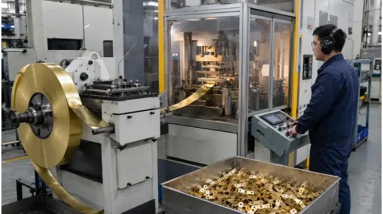
Brass stamping is a cold-forming manufacturing process that uses a mechanical or hydraulic press and custom steel tooling to cut, bend, and shape brass sheets or coils into high-volume, precise parts for industrial and electrical applications.
While brass offers excellent formability, specifying the wrong alloy temper, grain direction, or die clearance will inevitably lead to fractured bends, heavy burrs, and rejected parts. A standard progressive die can hold ±0.05 mm on critical features, but demanding ±0.02 mm globally will unnecessarily double your tooling maintenance costs.
This guide provides the exact engineering data you need to select the right material, apply realistic DFM rules, choose the most cost-effective tooling route, and prevent defects before the die is built.
Brass Stamping
Before the Die Is Built: Know the Brass You Are Forming
Selecting brass for a stamped part requires balancing forming suitability with end-use performance. The same nominal alloy will behave differently in the press depending on its physical temper and work hardening properties.
Alloy Selection for Forming and Service
Alloy
Forming Suitability
Main Advantage
Typical Parts
Manufacturing Note
C26000
Excellent in suitable temper
Deep drawing and complex forming
Housings, terminals, clips
Confirm temper and grain direction
C26800/C27200
Good
General forming and appearance
Covers, brackets, hardware
Confirm availability and finish
C46400
Moderate
Marine corrosion performance
Marine hardware and exposed parts
Verify corrosion and forming requirements
C36000
Limited
Excellent machining
Turned fittings and machined parts
Poor default for severe bends or drawing
C26000 (Cartridge Brass) provides the standard baseline for deep drawing and complex bending due to its optimal 70/30 copper-zinc ratio. However, it is not an automatic answer for every component.
A common engineering error is specifying C36000 (Free-Cutting Brass) for parts that require sharp bends. C36000 contains lead to break chips during CNC turning, which reduces ductility and causes the material to fracture during cold forming. If C36000 must be used for electrical or compliance reasons, note that RoHS Exemption 6(c) currently allows up to 4% lead in copper alloys, but supplier documentation must be flawless.
For parts exposed to saltwater or continuous moisture, C46400 (Naval Brass) uses a 1% tin addition to prevent dezincification, ensuring the component retains structural integrity over time.
Temper, Grain, and Work Hardening
The temper of the brass dictates its yield strength and elongation. Substituting a Half-Hard (H02) brass with a Spring (H08) temper will lead to severe springback or outer-radius fracturing.
Brass work-hardens rapidly during cold forming. Each deformation increases strength but decreases ductility. For deep-drawn shells or parts with multiple severe bends, the tooling process must account for this by either adding more forming stations to distribute the strain, or introducing an intermediate stress-relief annealing process between operations.
Specifying only “brass” is not enough. The drawing should state the exact alloy, temper code (e.g., H02), thickness, and applicable material standard.
Conductivity, Corrosion, and Compliance
Material selection directly impacts secondary operations and end-use environments. Zinc content changes electrical conductivity, which is critical for stamped terminals and battery contacts.
Traceability and compliance must be established before the first blank is cut. Production controls rely on incoming material certificates (Mill Test Reports) to verify the exact chemistry, mechanical properties, and REACH/RoHS compliance for every brass coil loaded onto the press feeder.
What the Drawing Must Get Right Before Tooling Starts
Modifying a CAD file takes minutes; modifying hardened tool steel takes weeks. The parameters below provide baseline Design for Manufacturing (DFM) rules to validate a drawing before tooling begins.
Holes, Slots, and Edge Distance
Feature
Typical Starting Point
Main Risk
Supplier Validation
Punched hole
Around 1.0 × thickness
Punch failure and burrs
Alloy, temper, tool material
Hole-to-edge distance
Around 1.5–2.0 × thickness
Edge distortion
Hole size and edge geometry
Narrow slot
Related to thickness
Punch breakage
Tool strength and volume
Hole near bend
Keep outside the main bend zone
Hole distortion
Radius, angle, and forming method
Punching a hole diameter smaller than the material thickness (1.0t) places extreme stress on standard tool steel. If a smaller hole (e.g., 0.8t) is required, the die maker must upgrade to Tungsten Carbide punches, which increases tooling cost.
Holes or slots placed too close to the material edge cause the remaining narrow web to bulge outward during the cutting stroke. When holes are located inside a bend zone, the material stretches and pulls the feature out of tolerance; these features must be moved or pierced after the bend is formed.
Regarding edge quality, stamping always creates some degree of burr. Industry standard allows a burr height of up to 10% of the material thickness; requiring a completely burr-free edge necessitates secondary mechanical deburring operations.
These values are starting points for DFM review. Final dimensions must be validated against the actual material and tooling process.
Bend Radius, Grain Direction, and Springback
A reliable bend depends on the orientation between the bend-line and the material’s rolling direction. Bending parallel to the grain increases the risk of cracking. The bend-line should ideally run perpendicular to the rolling direction.
For C26000, bending perpendicular to the grain allows an inside radius of 1.0t for a Half-Hard (H02) temper, but requires at least 2.0t for Hard (H04) or Spring (H08) tempers to prevent grain boundary separation.
Springback varies with alloy, temper, thickness, bend radius, and forming method. Compensation should be confirmed through forming trials or previous production data.
To correct springback, toolmakers use overbending (pushing the bend slightly past the target angle) or bottoming (compressing the radius at the bottom of the press stroke) to set the final geometry.
Drawing, Radii, and Tool Clearance
Deep drawing requires precise control of material flow. If the blank holding force is too high, the brass thins and tears. If it is too low, the material buckles and causes wrinkling on the flanges or walls.
Condition
Likely Result
Improvement Direction
Small drawing radius
Tearing and thinning
Increase the radius
Excessive draw depth
Cracking
Add forming stages
Low holding force
Wrinkling
Improve blank control
Excessive clearance
Large burrs
Reduce and validate clearance
Insufficient clearance
High force and tool wear
Increase and validate clearance
Cutting clearance—the gap between the punch and the die block—is critical for edge quality. For brass, optimal per-side cutting clearance typically ranges from 5% to 8% of the material thickness. This is tighter than standard steel requirements. A clearance outside this window results in excessive burrs, rapid tool wear, or galling (metal pickup on the tooling).
Tooling Choice Sets the Upfront Cost and Unit Price
Selecting a stamping process is an economic decision based on part geometry, material yield, and production volume. Procurement teams must evaluate the total cost of ownership rather than looking at tooling quotes in isolation.
Prototype and Single-Operation Routes
Before freezing a design, early prototypes and low-volume runs should utilize laser cutting, CNC punching, and standard press brake bending. These methods require minimal setup costs and allow for rapid design iterations, though the unit price remains high.
Once the design is stable but volumes are still low (typically under 5,000 pieces), single-operation dies or simple stage tooling become practical. A single-operation die performs one task per press stroke—such as blanking the perimeter or piercing a hole pattern. While tooling costs are low, the process requires manual or robotic transfer between secondary operations, which increases labor costs and introduces handling variables.
Engineers must account for the tolerance shift between prototyping and mass production. A CNC laser cutting a brass flat pattern will hold different edge conditions and tolerances than a hardened steel blanking die. Production tooling should only be approved after the CAD design is fully frozen.
Low initial tooling cost can lead to higher handling and unit cost. The best route depends on design stability and total expected demand.
Compound, Progressive, and Transfer Dies
For high-volume production, tooling strategy shifts toward automation and consolidating operations into a single press cycle.
Tooling Route
Suitable Parts
Main Advantage
Main Limitation
Single-operation die
Simple or limited-volume parts
Lower tooling complexity
More handling
Compound die
Flat parts with several cut features
Multiple cuts in one stroke
Limited forming capability
Progressive die
Stable repeat production
Fast and consistent output
Higher initial investment
Transfer die
Larger or complex formed parts
Flexible multi-stage forming
Complex handling and equipment
Multi-stage drawing
Deep hollow parts
Controlled material flow
More stations and validation
Strip Layout and Break-Even Cost
For a progressive die, the strip layout determines the project’s profitability. The layout dictates the number of die stations, the strip width, the progression (pitch), and the web width (the material left between blanks).
Material utilization is critical when stamping brass. Unlike carbon steel, brass skeleton scrap can recover 40% to 60% of the raw material cost depending on market rates. An optimized layout balances this scrap recovery against the progression pitch and nesting efficiency. A layout that yields only 55% utilization will permanently inflate the unit cost, whereas interlocking the parts to achieve 75% utilization directly impacts the bottom line.
Total Cost = Material + Tooling Amortization + Stamping + Secondary Operations + Inspection + Packaging
Tooling amortization depends heavily on expected die life, maintenance intervals (sharpening), and the project’s overall lifespan.
Progressive tooling should be selected from a break-even calculation, not from a universal order-quantity threshold.
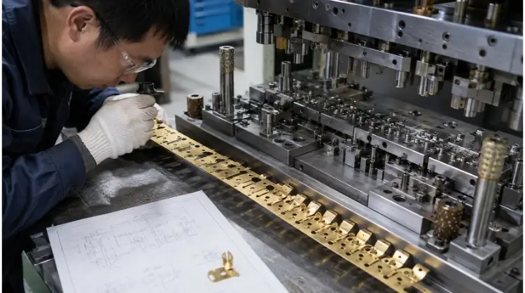
Progressive Strip Beside an Open Production Die
What Burrs, Cracks, and Scratches Tell You
Visual defects on a stamped brass part are diagnostic indicators of tooling conditions, material issues, or process instability. Identifying the root cause early prevents generating thousands of rejected parts.
Burrs and Dimensional Drift
A clean sheared edge indicates proper punch-to-die clearance and sharp tooling. When burrs begin to increase in height or thickness, it points directly to tooling wear, punch deflection, or incorrect clearance for the specific brass temper being run.
Dimensional drift over a production run usually traces back to feeding errors. If the coil feeder is miscalibrated by fractions of a millimeter, the die’s pilot pins will aggressively pull and elongate the pilot holes. This leads to wandering bend lines and feature shift across the entire strip. Changes in the ambient temperature of the tool or variations in the raw material’s yield strength can also alter springback, pushing formed angles out of tolerance.
Deburring removes the symptom. It does not correct a worn or incorrectly set die.
Cracks, Tearing, and Wrinkling
Defect
Likely Cause
Corrective Direction
Bend cracking
Hard temper, small radius, or poor orientation
Change temper, radius, or layout
Draw tearing
Excessive strain or poor lubrication
Add stages or improve lubrication
Wrinkling
Poor blank-holder control
Adjust holding force
Uneven wall thickness
Unbalanced material flow
Change blank shape or radii
Excessive springback
Material strength or tooling angle
Adjust tooling compensation
Brass-Specific Risk: Delayed Season Cracking
Season cracking can occur after forming when residual tensile stress combines with an aggressive environment (such as ammonia vapors or high moisture). It should not be confused with immediate bending or drawing cracks. Material condition, stress relief, cleaning, packaging, and service exposure must be reviewed together.
To mitigate season cracking, highly stressed parts often require a low-temperature stress-relief annealing process immediately after forming. The specific temperature and time profile must be tailored to the exact alloy, temper, and part geometry.
Tool Pickup, Scratches, and Tarnish
Tool pickup (often called galling) occurs when microscopic particles of brass cold-weld to the steel tooling under extreme pressure. This creates a rough buildup on the punch or die radius, which then gouges deep scratches into subsequent parts.
Scratches and surface defects can also originate outside the press. Metal shavings left on the die, insufficient stamping lubricant, or aggressive part-on-part friction as components drop into a collection bin will damage cosmetic surfaces. Similarly, dark spots or tarnish often result from stamping oil residue, acidic fingerprints from operators, or watermarks left during washing.
When addressing tool pickup and surface defects, the shop floor should follow a strict troubleshooting hierarchy:
Clean the die and remove all debris.
Check cutting clearances and inspect for tool deflection.
Improve the surface polish on the drawing radii.
Adjust the type or application volume of the stamping lubricant.
Improve part handling and stacking at the press exit.
Only after exhausting these steps, evaluate upgrading the tool steel (e.g., from D2 to M2 or Tungsten Carbide) or applying PVD (like TiCN) coatings to reduce friction.
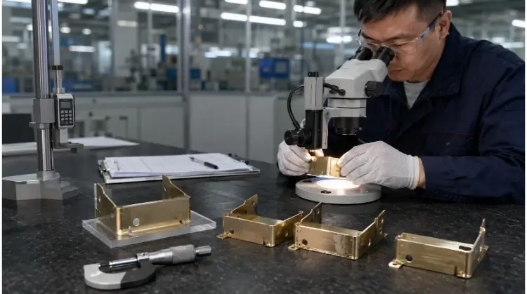
Brass Parts Under Defect Inspection
What Turns a Good Sample into a Stable Production Run
A successful prototype or first-off sample only proves that a part can be made. Scaling that success into tens of thousands of identical components requires strict process control, defined inspection criteria, and robust traceability.
First Article and Process Capability
Before mass production begins, a First Article Inspection (FAI) must be performed against the frozen drawing revision. This inspection verifies all critical dimensions, including flatness, true position, hole pitch, bend angles, wall thickness in drawn areas, and maximum burr height.
A good first article proves the setup. Process monitoring proves that the same result can be maintained throughout production.
However, passing an FAI does not guarantee long-term stability. As the die heats up and the tooling wears, dimensions will naturally drift. To control this, engineers use the Process Capability Index (Cpk).
A common mistake is applying a high capability requirement (e.g., Cpk ≥ 1.33, the standard for automotive PPAP) to every dimension on the print. This forces the stamping facility to pause production frequently for minor tool adjustments, driving up costs unnecessarily. Cpk tracking should be strictly reserved for critical-to-function features, such as press-fit hole diameters or critical mating profiles. Die maintenance logs should dictate when punches and dies are sharpened, rather than waiting for a part to fail inspection.
Cleaning, Bright Dipping, and Anti-Tarnish Protection
Brass parts rarely leave the press ready for assembly. The stamping process leaves sharp edges, micro-burrs, and residual forming oils that must be addressed.
For cosmetic brass parts, vibratory tumbling often uses softer media like walnut shells or corn cob instead of heavy ceramics to remove burrs without peening or dimpling the surface. Following deburring, the parts must be thoroughly cleaned. Residual stamping oils will degrade cosmetic appearances and cause severe adhesion failures if the part is later plated or soldered.
If the brass is to be left bare, it usually undergoes bright dipping (a mild acid bath to remove surface oxidation) followed by an anti-tarnish treatment. Bare brass reacts quickly with oxygen, tarnishing in a matter of days. Applying an organic inhibitor (such as Benzotriazole) creates an invisible barrier that typically provides 6 to 12 months of shelf life during storage and marine transit without affecting future solderability.
When plating is required, the coating must align with the part’s function:
Tin plating: Used for electrical terminals to ensure excellent solderability.
Nickel plating: Provides a hard, wear-resistant, and aesthetically pleasing finish.
Selective Gold plating: Used on contact points for critical conductivity and corrosion resistance.
Engineering Note: Plating adds physical thickness. A 5-micron nickel plating adds 10 microns to the overall diameter of a punched hole. The stamping die clearance and baseline punch dimensions must be designed to account for this final plating thickness to ensure mating parts still fit.
Packaging, Traceability, and Supplier Evidence
The physical handling of brass components is just as critical as the stamping itself. Brass is relatively soft and scratches easily. Dropping cosmetic parts in bulk into a heavy bin will destroy the surface finish. Cosmetic parts require isolated packaging, such as custom thermoformed trays or layered foam separators.
Additionally, sea freight and long-term warehouse storage expose bare or lightly protected brass to extreme humidity and salt air. Shipments must utilize Volatile Corrosion Inhibitor (VCI) bags or desiccants to prevent oxidation before the parts reach your assembly line.
For critical applications (such as automotive or medical), strict traceability is required. The manufacturer must be able to link any finished part back through the plating batch, the specific inspection record, and ultimately to the original raw material master coil. This is typically managed through formalized frameworks like PPAP (Production Part Approval Process) or comprehensive Control Plans.
Conclusion
Brass stamping quality is not controlled by press tonnage alone. Alloy, temper, grain direction, part geometry, strip layout, tooling, and inspection must work together.
Finding these risks before tooling begins is usually faster and less expensive than modifying a completed production die.
Send us your drawing, brass alloy, temper, thickness, annual volume, critical tolerances, and finishing requirements. Our engineering team can review the part for forming risks, tooling options, material use, and production cost before tooling begins.
Share This Article
Table of Contents
Send Your inquiry
Kevin Lee
Kevin Lee has over a decade of experience in the sheet metal industry, specializing in precision fabrication and problem-solving. With a strong focus on quality and efficiency, he brings valuable insights and expertise to every project, ensuring top-notch results and customer satisfaction in all aspects of metalworking.

 English
  Spanish
  German
  Russian
  Italian
  French