
 English
  Spanish
  German
  Russian
  Italian
  French
Heliarc welding is the original trade name for Gas Tungsten Arc Welding (GTAW) or TIG welding. It uses a non-consumable tungsten electrode and inert shielding gas to produce highly precise, spatter-free welds. In modern manufacturing, Heliarc and TIG are the exact same process.
If you see “Heliarc” specified on a legacy engineering drawing, your fabricator will quote and process it as standard TIG welding. While the terminology has evolved, the manufacturing challenges remain identical. This process is the ultimate choice for thin sheet metal, sanitary stainless steel, and cosmetic aluminum enclosures, but it comes with a steep cost: it is slow, heavily reliant on operator skill, and unforgiving of poor joint fit-up.
This guide explains how material, joint design, heat control, inspection, and production volume affect heliarc welding quality and cost.
What Heliarc Welding Means in Modern Manufacturing?
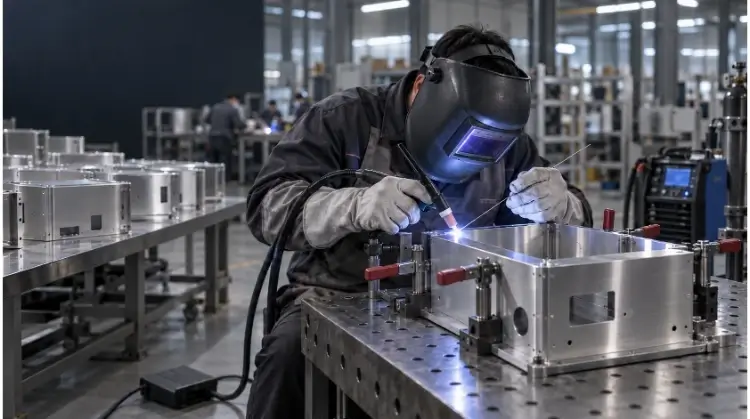
Using the term “heliarc” on a drawing today simply signals the shop floor to use Gas Tungsten Arc Welding (GTAW). To estimate costs and understand potential defects, engineers and purchasing managers must understand how the equipment physically interacts with the metal.
The Tungsten Arc and Gas Shield
In this process, the machine sends current through a tungsten electrode to create an arc, melting the base metal. Simultaneously, a nozzle directs shielding gas over the pool to displace oxygen and nitrogen. The term “heliarc” stuck from early helium use, but argon is now the industry standard due to its lower cost and stable arc starts.
The core manufacturing advantage here is the separation of heat input and material addition. The tungsten carries the arc. It does not normally become the weld filler.
Gas flow rate is a critical parameter. Insufficient flow leaves the molten metal exposed to the atmosphere, causing immediate contamination that cannot be ground out, often resulting in complete part scrap. Conversely, excessive gas flow creates turbulence that pulls surrounding air into the weld zone, causing the exact same defect.
Filler Metal and Autogenous Welding
Because the tungsten does not melt, operators must manually feed a separate filler rod into the weld pool if the joint requires extra material.
However, not all TIG welds use filler wire. Autogenous welding (fusion welding) relies entirely on melting the existing edges of the base metal. This works well for thin materials (under 1.5mm) with perfectly flush fit-ups, such as outside corner joints on sheet metal enclosures.
When a gap exists between parts, autogenous welding will fail. The operator must introduce filler metal to bridge the gap. The specific grade of the filler rod directly dictates the final joint’s mechanical strength, crack resistance, and corrosion properties. Therefore, TIG should not be categorized simply as “welding without wire”—the decision depends entirely on joint geometry and tolerance stack-up.
Equipment, Setup, and Safety
A standard industrial TIG setup requires an AC/DC constant-current power supply. The operator controls the amperage dynamically using a foot pedal or a torch-mounted slider, which is essential for managing heat buildup as the weld progresses. Torches are air-cooled for thin parts or water-cooled for heavy, continuous welding.
Workplace safety directly impacts production consistency. Operators require helmets with auto-darkening filters to block intense UV radiation, heat-resistant gloves that allow finger dexterity for wire feeding, and local exhaust ventilation to manage welding fumes and prevent argon asphyxiation in confined spaces.
The baseline production sequence follows a strict order:
Clean (Degrease & Brush) → Fit and Fixture → Set Current and Gas Flow → Tack Weld → Complete Final Weld → Inspect Part
How Heliarc Settings Change With the Base Metal?
There are no universal TIG parameters. Current type, gas selection, and heat management change drastically depending on the material’s thermal conductivity and chemical properties.
Aluminum: Oxide and Heat Flow
Welding aluminum alloys like 5052 and 6061 presents two distinct manufacturing challenges: a high-melting-point surface oxide layer and rapid thermal conductivity.
Aluminum requires Alternating Current (AC). The positive half of the AC cycle breaks up the tough oxide layer, while the negative half penetrates the base metal. Because aluminum dissipates heat quickly, operators must start with high amperage to form a puddle, then taper the current down via the foot pedal to avoid burn-through.
For thin aluminum enclosures (e.g., 1.5mm 5052), strict heat control and dedicated fixturing are required to prevent distortion. Filler wire selection also impacts post-processing. If the part requires clear anodizing, using standard 4043 filler leaves a distinct dark gray weld line. In these cases, 5356 filler is usually specified to ensure color matching.
Stainless Steel: Heat Tint and Corrosion
Stainless steel grades like 304 and 316L retain heat locally, increasing the risk of distortion and metallurgical damage. This material is welded using Direct Current Electrode Negative (DCEN).
The primary risk is excessive heat input, which expands the Heat-Affected Zone (HAZ) and degrades the material’s rust-resistant passive layer, visible as a dark “heat tint.” To prevent oxidation on the backside of the joint, operators must use back purging—flooding the interior of the part with argon gas.
Engineers must note: A visually clean weld is not automatic proof of corrosion resistance. Even well-executed TIG welds on food-grade or medical stainless parts typically require post-weld pickling and passivation treatments to restore full corrosion resistance. Buyers should factor in this post-processing time when calculating lead times. Our inspection standards for these joints typically reference AWS D1.6.
Carbon Steel and Specialty Alloys
Carbon steel is forgiving regarding heat input but unforgiving regarding surface contamination. Mill scale, rust, oil, or zinc coatings must be completely ground off before TIG welding; otherwise, the weld will suffer from severe porosity and lack of fusion. DCEN and pure argon are standard here.
Specialty alloys require extreme environmental control:
- Titanium: Highly reactive to oxygen and nitrogen at elevated temperatures. It requires ultra-high-purity argon, large gas lenses, and trailing gas shields. Failure to properly shield titanium results in a brittle, discolored weld that often requires complete scrapping of the expensive raw material.
- Copper Alloys: Extremely high thermal conductivity requires maximum heat input, often utilizing helium-argon gas mixtures to increase arc voltage and penetration.
- Nickel Alloys: Highly susceptible to hot cracking. They require very clean surfaces, controlled heat input, and convex weld bead profiles to prevent structural failure.
Material Selection Matrix
| Base Material | Common Current Mode | Standard Shielding Gas | Primary Manufacturing Risks |
| 5052 / 6061 Aluminum | AC | Argon (or Ar/He mix) | Oxide contamination, rapid burn-through, thermal distortion |
| 304 / 316L Stainless | DCEN | Argon | Heat tint (carbide precipitation), distortion, loss of corrosion resistance |
| Carbon Steel | DCEN | Argon | Porosity from surface oil/rust, lack of fusion |
| Titanium Alloys | DCEN | High-purity Argon | Oxidation embrittlement (requires trailing gas shields) |
| Copper Alloys | DCEN | Argon or Ar/He mix | Rapid heat loss, insufficient penetration |
(Note: Exact welding parameters ultimately depend on material thickness, joint design, welding position, and specific inspection criteria such as AWS D1.2 for aluminum or AWS D1.6 for stainless steel.)
How Joint Design Reduces Distortion and Finishing Work?
The most effective way to lower TIG welding costs is not by forcing operators to weld faster, but by designing parts that are easier to weld. Design for Manufacturing (DFM) in sheet metal focuses on optimizing weld accessibility, controlling tolerance stack-up, and implementing distortion mitigation strategies before the first laser cut is made.
Joint Fit-Up and Torch Access
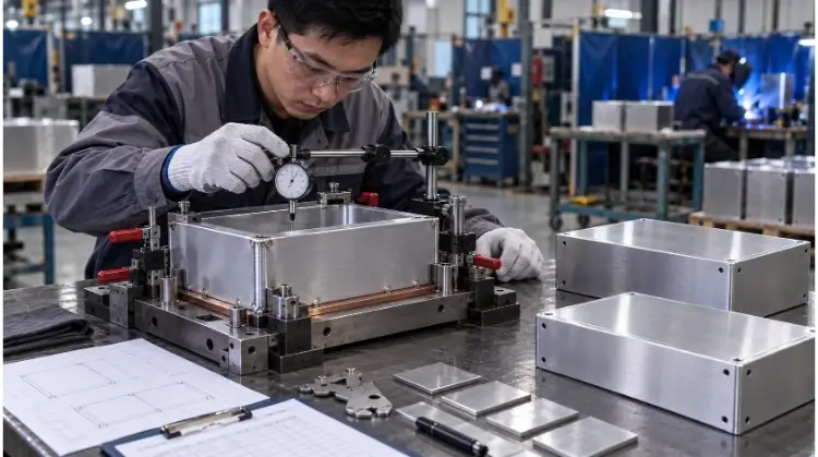
Consistent joint fit-up is critical for TIG welding. While MIG welding can easily bridge wide gaps by dumping wire into the joint, TIG requires tight tolerances. A gap larger than 0.5mm on thin sheet metal forces the operator to slow down and input excessive heat to bridge the joint, significantly increasing the risk of distortion and burn-through.
Weld accessibility is equally important. The operator needs a clear line of sight and physical space to angle the torch (usually at 15–20 degrees) while simultaneously feeding the filler rod. Furthermore, engineers should evaluate if a continuous weld is structurally necessary. Replacing welded corners with CNC bent edges, or utilizing intermittent (stitch) welds, can drastically reduce overall heat input.
| Design Issue | Manufacturing Result | DFM Solution |
| Restricted inner corner access | Unstable torch angle, lack of fusion | Increase clearance or redesign to an outside corner joint |
| Lack of self-locating features | Inconsistent batch gaps, high fixturing time | Add tab-and-slot features or locating flanges in CAD |
| Over-specified continuous welds | Severe distortion, increased grinding labor | Shorten welds, use stitch welding, or move to hidden faces |
| Holes too close to the weld seam | Hole distortion and positional shift after cooling | Increase distance or machine the holes after welding |
Fixtures, Tack Welds, and Sequence
Even with perfect joint design, the extreme heat of the TIG arc will pull and warp metal as it cools. Managing this thermal load requires strict fixturing and sequencing.
Heavy-duty clamps and custom jigs are used to hold the parts and act as heat sinks. Inserting copper backing bars behind the weld seam draws heat away from the thin base metal. Before laying a continuous bead, operators place tack welds along the joint. To prevent a long sheet from bowing, operators must avoid welding in a single, continuous line, relying instead on symmetric welding, step-back welding, or skip welding to distribute the heat evenly.
Engineers must account for production scale. A fixture that remains cool during a single prototype run can suffer from severe thermal saturation during a 500-part batch run, leading to unexpected tolerance drift. Therefore, cooling periods and sequence adjustments must be engineered into the production routing.
Heat Control and Surface Finish
The operator’s management of current, arc length, and travel speed directly dictates heat accumulation. On thin materials, modern machines utilize pulsed TIG—alternating between a high peak current for penetration and a low background current to let the puddle chill.
However, heat inherently affects surface finish. Stainless steel will show heat tint, and aluminum will experience localized changes in grain structure, often leading to color mismatch after anodizing if the wrong filler wire is used.
Purchasing managers often focus on the hourly rate of the welding itself, missing the hidden costs of post-processing. In precision sheet metal fabrication, grinding, blending, and restoring a brushed surface finish can often take 3 to 5 times longer than the actual welding process.
Low spatter can reduce finishing work, but it does not eliminate surface preparation.
Why Good-Looking TIG Welds Still Fail Inspection?
The aesthetic appeal of TIG welding can be deceiving. A weld can display a perfectly uniform, shiny “stack of dimes” appearance on the surface and still fail structural or leak testing. Quality control requires moving beyond basic visual checks to identify internal defects and verify dimensional stability.
Weld Defects and Root Causes
| Defect Type | Common Causes | Inspection / Corrective Action |
| Porosity | Oil, moisture, or inadequate gas coverage | Clean metal thoroughly; check gas flow and wire storage |
| Severe Oxidation / Blackening | Insufficient shielding gas coverage | Adjust cup size, stick-out distance, and post-flow gas time |
| Tungsten Inclusion | Tungsten touching the weld pool or filler rod | Maintain proper arc length and torch control |
| Lack of Fusion | Insufficient current or travel speed too fast | Increase heat input; ensure correct torch angle and joint prep |
| Cracking | Mismatched filler wire or poor crater fill at the end | Verify filler grade; use downslope current to fill the crater |
| Distortion | Excessive heat input or incorrect weld sequence | Improve fixturing; utilize pulsed TIG or skip welding |
It is critical to distinguish between cosmetic flaws and structural failures. For example, slight surface oxidation on a stainless bracket might be acceptable for a dry indoor environment, but it is a critical failure for sanitary equipment.
More dangerously, an inexperienced operator can easily create a beautiful “stack of dimes” on the surface while completely failing to melt the root of the joint. This condition, known as “cold roll” or lack of root penetration, is a fatal structural flaw for load-bearing components. Tungsten inclusion is another defect unique to TIG, occurring when the electrode tip snaps off into the weld pool, creating a brittle stress point.
Visual, NDT, and Leak Testing
Inspection methods must align strictly with the part’s risk profile; vaguely specifying “inspect to international standards” drives up costs unnecessarily.
Standard Visual Testing (VT) verifies weld size, profile, and the absence of surface cracks. For higher reliability, Dye Penetrant Testing (PT) draws a highly visible dye into microscopic surface-breaking cracks. If an enclosure houses sensitive electronics, pneumatic or hydrostatic leak testing is mandatory.
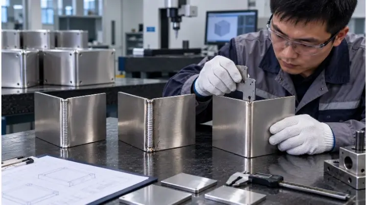
For critical components, manufacturers may require destructive testing on sample coupons or macroscopic cross-sections to verify actual root penetration. Finally, inspectors must perform post-weld dimensional checks—verifying hole positions and panel flatness—to guarantee the welded sub-assembly will mate properly in the final product.
WPS, First Articles, and Batch Control
Reliable batch production cannot rely on an individual operator’s memory. The exact parameters that produce a successful weld are documented in a Welding Procedure Specification (WPS), supported by a Procedure Qualification Record (PQR).
Maintaining quality across a batch requires a systematic workflow:
Trial Weld → First Article → Parameter Approval → Batch Production → Process Inspection
Once the First Article Inspection (FAI) passes, the welding parameters, fixturing setup, and welding sequence are locked. During batch production, quality teams conduct scheduled sampling to ensure that heat accumulation over multiple hours of welding has not introduced tolerance drift.
When auditing a new sheet metal supplier, buyers should always ask to see their WPS documents and First Article Inspection reports—facilities that rely solely on “operator feel” cannot guarantee consistency across a high-volume run.
Heliarc vs. MIG Welding: Quality, Speed, and Cost
Purchasing managers often focus on the slow travel speed of TIG welding when comparing quotes. However, evaluating the actual cost of a welded assembly requires looking at the entire production cycle, not just the minutes spent under the arc.
TIG vs. MIG and Laser Welding
Different welding processes offer distinct advantages depending on the material thickness, joint design, and production volume.
| Criteria | TIG (Heliarc / GTAW) | MIG (GMAW) | Laser Welding |
| Welding Speed | Slower | Faster | Very Fast |
| Heat Control on Thin Metal | Better | Moderate | Better |
| Weld Appearance | Usually clean and precise | May require post-weld cleanup | Narrow, minimal bead |
| Gap Tolerance (Fit-Up) | Moderate (Requires tight fit) | Relatively high (Can bridge gaps) | Requires strict consistency |
| Skill / Setup Requirement | High manual welder skill | Moderate manual skill | High process development |
| Automation Investment | Moderate to High | Moderate | High |
When reviewing a new project, manufacturing engineers generally apply the following routing rules:
- Evaluate TIG first for thin sheet metal, precision assemblies, and highly visible cosmetic joints.
- Evaluate MIG first for thicker plates (typically > 3.0mm) and high-yield structural components where speed is prioritized over aesthetics.
- Evaluate Laser Welding for medium-to-high volume production where the assembly fit-up is highly stable and repeatable.
Labor, Finishing, and Rework
To understand why TIG can be more cost-effective despite its slower speed, buyers must calculate the total cost of ownership for the welded joint:
Total Welding Cost = Setup + Labor + Gas and Filler + Fixturing + Finishing + Inspection + Rework + Scrap
MIG welding deposits metal quickly, which lowers the direct labor time for the welding step itself. However, MIG often produces spatter and requires heavier weld beads. If the part requires a smooth, painted, or cosmetically clean surface, the labor saved during welding is immediately lost in the grinding, blending, and polishing stages.
In cosmetic sheet metal projects, finishing and rework can account for up to 60% of the total assembly cost. Choosing TIG to eliminate spatter is a strategic cost-saving decision. For a stainless steel enclosure requiring a #4 brushed finish, a TIG weld with zero spatter often yields a lower total unit cost because it bypasses hours of aggressive post-weld grinding. Unit costs also scale efficiently; as production quantities increase, the initial tooling costs (custom heat-sink fixtures) are amortized over the life of the project.
Manual, Cobot, and Robotic TIG
Scaling TIG production introduces automation to reduce reliance on hard-to-find manual welding talent.
- Manual TIG works well for prototyping, low-volume runs, and high-mix projects where joint access is complex.
- Cobot (Collaborative Robot) TIG is suited for medium-volume production with repetitive seams. Operators can program the arm quickly by guiding it along the joint, making it practical without massive setup delays.
- Robotic TIG is reserved for highly stable, high-volume production. It requires heavy capital expenditure for rigid fixturing and automated wire-feed systems. More importantly, it demands strict ±0.1mm tolerances from upstream laser cutting and bending operations; otherwise, the robot will simply weld empty air.
When evaluating automated TIG, production planners must remember a physical constraint:
Automation improves consistency and reduces direct labor, but it does not remove TIG’s deposition-rate limits.
The arc still melts the metal at the same physical speed; the ROI comes from continuous machine uptime and lower defect rates, not faster travel speeds.
Conclusion
TIG welding (Heliarc) is a highly controllable, clean process that produces exceptional mechanical and aesthetic results. It is the optimal choice for thin sheet metal, precision enclosures, and highly visible joints.
MIG welding becomes more cost-effective for thicker structural parts, while laser welding offers unparalleled speed for high-volume, tightly toleranced assemblies. Ultimately, the right process depends on the base material, thickness, joint geometry, allowable tolerances, cosmetic expectations, and total production volume.
Not sure whether TIG, MIG, or laser welding fits your part?
Send us your drawing, material grade, thickness, weld requirements, surface finish, and expected quantity. TZR’s engineering team will review the joint design, distortion risks, inspection requirements, and total production cost, providing a detailed DFM report and quotation within 24 hours.