
 English
  Spanish
  German
  Russian
  Italian
  French
Laser welding aluminum requires strict control over heat input, surface cleaning, and joint fit-up to prevent porosity and hot cracking. Consistent success depends on pairing a fiber laser with the correct shielding gas and filler wire for specific 5xxx and 6xxx series alloys.
While the process delivers narrow, clean joints with minimal thermal distortion, aluminum’s high thermal conductivity and stubborn oxide layer make its process window remarkably tight. A 0.2mm gap variation or a skipped degreasing step will instantly turn a structural seam into scrap.
Aluminum laser welding can produce narrow, clean joints with low distortion, but small changes in alloy, surface condition, joint gap, or heat input can cause porosity, cracking, and incomplete fusion. This guide explains how to design, test, inspect, and control aluminum laser-welded parts from prototype trials to production.
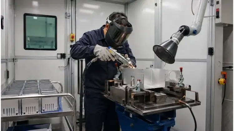
Opening Process Check
The following table provides an initial direction based on specific part requirements. Note that this is a preliminary screening tool and does not replace procedure qualification or mechanical testing.
| Project condition | Initial process direction |
| Thin sheet with strict distortion limits | Laser welding is a strong candidate |
| Repeatable seams and stable fixtures | Well suited to automated laser welding |
| Variable gaps or inconsistent edges | Improve fit-up or evaluate wobble and filler wire |
| One-off parts with short welds | TIG may have a lower total setup cost |
| Thick joints or larger gaps | Compare laser, MIG, or hybrid processes |
| Airtight or pressure-bearing parts | Require procedure qualification and leak testing |
| Crack-sensitive aluminum grades | Complete grade-specific welding trials |
How Aluminum Alloy and Temper Affect Laser Weldability?
Aluminum weldability depends on chemical composition, temper, and the filler metal used. These factors directly dictate the occurrence of porosity, hot cracking, and post-weld joint strength.
Oxide Film, Heat Flow, and Laser Absorption
The physical properties of aluminum require strict process controls. Understanding these baseline characteristics explains why the process window is relatively narrow.
- Pure aluminum melts at approximately 660°C, but the protective aluminum oxide layer melts at around 2050°C.
- Commercial aluminum alloys have a melting temperature range; calculations based solely on pure aluminum data are inaccurate.
- High thermal conductivity rapidly draws heat away from the weld joint.
- A low base melting point increases the risk of local burn-through on thin sheets.
- Laser absorption rates are not static—they vary depending on the laser wavelength, surface roughness, and material temperature.
- Surface reflectivity affects start-up stability—often resulting in an erratic initial bead or “spitting” before the keyhole fully forms—and can pose severe back-reflection risks to the optical system.
- Keyhole instability during deep penetration welding may cause spatter and internal porosity.
Alloy Series, Temper, and HAZ Strength
Not all aluminum grades behave the same way under a laser beam. Weldability varies significantly across alloy series and tempers.
- 1xxx and 3xxx series usually exhibit good weldability.
- 5xxx series can generally be welded, but the filler wire and operating temperature must account for the specific magnesium content.
- 6xxx series requires strict control over filler metal selection to prevent solidification cracking, and it will experience distinct softening in the heat-affected zone (HAZ).
- Certain 2xxx and 7xxx series grades have limited weldability and require grade-specific trials before production.
- Cast aluminum parts often contain inherent internal porosity, which can expand and cause severe defects during laser welding.
Material temper dictates the mechanical properties of the final joint:
- O (annealed), H (strain-hardened), T4, and T6 tempers cannot use the same post-weld strength assumptions.
- Both work-hardened and heat-treated aluminum alloys lose a portion of their strength in the HAZ after welding.
- The post-weld behavior of 5052-H32 cannot be directly applied to 6061-T6.
- A cosmetically acceptable weld bead does not indicate that the joint strength matches the base metal.
- Parts subjected to fatigue, heavy loads, or pressure require independent mechanical validation.
Autogenous Welding and Filler Wire
Laser welding can be performed with or without filler wire, depending on the joint configuration and alloy chemistry.
- Autogenous welding (no filler) works well for joints with small gaps, stable edges, and compatible base metal chemistry.
- Filler wire supplements weld metal to compensate for gaps and improves fit-up tolerance.
- Wire addition alters the weld seam chemistry, which is often necessary to reduce the hot cracking risk in specific alloys.
- Standard filler wires like 4043, 4047, and 5356 cannot be automatically paired with base metals based solely on the alloy series.
- Filler selection must simultaneously address tensile strength, ductility, cracking resistance, and operating environment (corrosion/temperature).
- Parts operating at sustained high temperatures require verification if a high-magnesium filler is used.
Expert Tip: If the final part requires clear anodizing, using 4043 filler wire on a 6061 base will result in a dark gray or black weld seam due to the silicon content. Switch to 5356 filler wire for color matching, provided the operating temperature remains below 65°C.
Base Metal and Filler Selection Guide
| Base Metal | Temper | Main Risks | Filler Direction | Surface Treatment Notes |
| 3003 | H14, O | Burn-through on thin sheets | 1100, 4043 | Good color match after anodizing |
| 5052 | H32, O | Porosity, Mg vaporization | 5356 | 5356 provides better color match than 4xxx series |
| 6061 | T6 | Hot cracking, HAZ softening | 4043, 5356 | 4043 reduces cracking; 5356 provides higher ductility |
| Cast (e.g., A356) | T6 | Extensive internal porosity | 4043, 4047 | Weld quality depends heavily on casting density |
(Note: This table provides general direction. It does not replace formal filler metal selection charts or welding trials.)
Joint Design and Fit-Up for Aluminum Laser Welding
The ability of a laser beam to consistently hit the seam depends heavily on joint geometry, cut edge quality, and fixturing stability.
Joint Types and Weld Access
Different joint configurations present specific challenges for laser systems.
- Butt joints provide a clean appearance but are highly sensitive to gaps and edge mismatch.
- Lap joints are easier to locate and fixture, but trapped contamination between the layers can cause porosity.
- Corner joints require sufficient clearance for the laser head, gas nozzle, and wire feeder.
- Flange joints improve fit-up stability and add rigidity to thin sheet metal enclosures.
- Airtight joints require a continuous, verifiable path for the laser head without sudden changes in angle.
- Single-sided welds require upfront planning for root formation and potential back shielding or support.
Gap, Mismatch, and Edge Condition
The assembly condition immediately before welding dictates the defect rate.
- Excessive gaps may cause underfill, undercut, or incomplete fusion.
- Edge mismatch alters the effective penetration depth and reduces the bonding area on one side.
- Burrs, dross, and inconsistent cut edges affect part positioning and seam tracking accuracy.
- Oxides, cutting fluids, adhesives, and moisture left on the cut edge will vaporize and enter the weld pool.
- Small spot sizes and autogenous setups are highly sensitive to seam position deviations.
- Sudden variations in the gap along the seam are more difficult to control than a consistent, small gap.
- Do not rely on a universal gap formula. The allowable gap depends on sheet thickness, spot size, beam wobble, filler wire, and target penetration, which must be determined through trials.
Engineering Rule of Thumb: As a general rule for autogenous laser welding, the maximum allowable gap should not exceed 10% of the material thickness, and mismatch should be kept under 5-10%. If your gap exceeds 0.5mm, filler wire or wobble functions become mandatory.
Fixturing and Weld Sequence
Laser welding requires precise part presentation. The fixture design must account for access and thermal expansion.
- Define clear datum surfaces and part locating methods.
- Control gap and mismatch repeatability through rigid tooling.
- Place clamping points close enough to the joint to maintain position, but far enough to avoid optical interference.
- Use copper backing for root support and localized heat dissipation where necessary.
- Ensure physical clearance for the laser head, gas nozzle, and wire feeding mechanism throughout the entire tool path.
- Confirm visual access if using seam tracking or vision systems.
- Plan start, stop, and overlap positions to avoid crater cracks.
- Use symmetrical or segmented welding sequences to manage accumulated thermal distortion.
- Factor in loading, unloading, and fixture cleaning time.
Laser welding cannot magically fix poor sheet metal fabrication. The accuracy of the upstream laser cutting, the precision of the CNC bending, and the repeatability of the fixture collectively dictate the final welding yield rate. If the fit-up is inconsistent, the laser will consistently weld nothing but air.
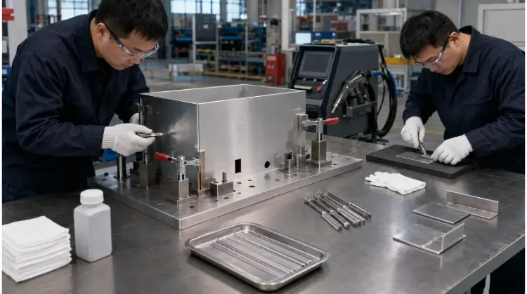
Setting the Aluminum Laser Welding Process Window
A stable aluminum laser welding process requires strict control over surface preparation, beam dynamics, shielding gas, and filler wire delivery. These variables must be configured sequentially on the shop floor to ensure repeatable results.
Surface Cleaning and Oxide Removal Sequence
Aluminum welding has zero tolerance for contamination. Preparing the surface requires a strict order of operations to prevent embedding pollutants into the base metal.
Material Check → Degreasing → Oxide Removal → Fit-Up → Welding
- Identify the specific aluminum alloy, its temper, and any existing protective films (e.g., PVC laser film).
- Use a suitable solvent to strip away cutting fluids, forming oils, adhesives, and moisture.
- Only after degreasing, remove the refractory oxide layer using a dedicated stainless steel wire brush, scraping tool, or approved chemical etch.
- Engineering Rule: Never use mechanical abrasion before chemical degreasing. Brushing an oily surface spreads the contamination and drives it into micro-scratches, making it nearly impossible to clean out and guaranteeing porosity.
- Cleaning tools must be strictly dedicated to aluminum; cross-contamination from carbon steel brushes will ruin the weld.
- Once cleaned, parts must not touch bare hands, dirty gloves, or contaminated workbenches.
- Filler wire must also be kept clean, dry, and stored in a climate-controlled environment.
- Control the time between cleaning and welding. Aluminum oxidizes rapidly; parts left sitting overnight usually require re-cleaning.
Process Window and Beam Wobble Dynamics
Laser welding generally operates in two modes. Conduction mode yields shallow penetration and a smooth surface profile. Keyhole mode achieves high aspect ratios (deep penetration), but if the keyhole collapses, it traps gas and generates heavy spatter.
The process window relies on the interaction of several parameters:
- Laser power and travel speed jointly determine the heat input per unit length.
- Focus position and spot size dictate the energy density at the workpiece surface.
- Beam shape and mode affect the stability of the molten pool.
- Beam wobble (oscillation) width and frequency alter the weld width and penetration profile.
- While wobble increases the gap tolerance for sheet metal assemblies, excessive wobble width dilutes the effective energy density, reducing penetration.
- Wobble functions cannot replace stable laser cutting and consistent fixturing.
- Start and stop points require specific power ramping (fade-in and fade-out) to prevent crater formation and initial spatter.
- If using automated seam tracking, the sensor resolution must match the required positioning accuracy of the focal spot.
Production Variable Check: The process window shifts if the protective cover glass becomes contaminated with spatter. A dirty lens absorbs laser energy, causing thermal lensing (a thermal shift of the focal point) and reducing power at the workpiece. Replace protective lenses proactively based on run time, not just when a weld fails.
(Note: Generic parameter tables are useless without context. Any parameter set requires specifying the alloy, temper, thickness, joint type, spot size, focal position, wobble pattern, wire feed rate, gas flow, and target penetration.)
Shielding Gas and Filler Delivery
Shielding gas protects the molten pool and affects beam transmission.
- Argon is the standard choice, but it is not the only option. Helium or Argon-Helium mixtures are often used for deep keyhole applications and thicker sections to increase heat input and suppress plasma formation.
- Gas purity, dew point, and moisture in the delivery lines must be strictly monitored.
- Low gas flow results in atmospheric contamination. High gas flow creates turbulence that pulls surrounding oxygen into the weld pool.
- The nozzle angle, standoff distance, and position relative to the beam must be tuned alongside the flow rate.
- Full-penetration joints usually require back-shielding or a grooved backing bar to protect the root.
Filler wire delivery must be physically and thermally stable:
- Cold wire feeding adds metal volume and adjusts the weld chemistry.
- Hot wire feeding increases deposition efficiency but requires complex synchronization with the laser system.
- Wire diameter and feed speed must match the volume of the molten pool.
- The wire must consistently enter the leading edge of the weld pool. If the wire deviates from the pool, it causes incomplete fusion, heavy spatter, or irregular chemistry distribution.
Laser Safety Requirements: Class 4 laser welding requires rigid safety protocols. Unlike the bright arc of TIG welding, the 1064nm wavelength of a fiber laser is invisible to the human eye and focuses directly onto the retina, causing instant, irreversible blindness. Light-tight enclosures, door safety interlocks, and OD-rated safety glasses matched to the specific wavelength are mandatory. Facilities must manage fire risks, install active fume extraction for toxic aluminum dust and ozone, and enforce standard operating procedures (SOPs) with documented operator training.
Common Aluminum Laser Weld Defects and Their Causes
Visual inspection is only the first step. Troubleshooting aluminum defects requires linking the failure mode back to material chemistry, surface prep, fit-up, or optical parameters.
Porosity and Keyhole Instability
Porosity in aluminum generally stems from two distinct sources: hydrogen contamination and process instability.
Contamination and Hydrogen Sources:
- Oil, moisture, or adhesive residue on the base metal or filler wire.
- Thick, hydrated oxide films or dross on laser-cut edges.
- Moisture trapped in shielding gas lines or using low-purity gas.
- Excessive wait times between cleaning and welding.
- Inherent internal voids present in cast aluminum base materials.
Keyhole and Process Sources:
- Repeated collapse of the keyhole during deep penetration welding.
- Turbulent flow within the molten pool.
- Mismatched travel speed, focus position, or beam shape.
- Rapid solidification rates that do not give gas bubbles enough time to escape the pool.
Visual inspection cannot detect internal porosity. Depending on the part’s function, validation requires cross-sectioning, X-ray, CT scanning, or leak testing.
Hot Cracking and Incomplete Fusion
These two defects look different and require entirely different corrective actions.
Hot Cracking (Solidification Cracking) typically involves:
- The specific chemical composition of the base metal and filler wire.
- The wide solidification temperature range of certain alloys (like 6xxx series).
- Incorrect filler wire selection.
- Excessive mechanical restraint from rigid fixturing.
- Poor weld bead profile (e.g., highly concave) or inadequate power ramping at the crater.
Incomplete Fusion typically involves:
- The laser beam physically deviating from the seam center.
- Insufficient heat input or shallow penetration.
- Variations in gap width or edge mismatch along the seam.
- Inconsistent cut edge quality causing the beam to reflect or scatter.
- Incorrect wire feed positioning or excessive wobble width.
- Poor control at the start/stop tie-in locations.
Expert Tip: Do not default to “increasing laser power” to solve incomplete fusion. While more power might push penetration deeper, it can simultaneously cause burn-through, severe spatter, or unnecessarily widen the weakened heat-affected zone (HAZ). Verify beam alignment and focus position first.
Soot, Burn-Through, Undercut, and Distortion
When inspecting the external bead profile and surrounding area, check for the following indicators:
- Black soot or dark deposits often result from contamination, vaporized magnesium, or poor shielding gas coverage.
- Check gas flow—excessively high flow rates cause turbulence that draws air into the shielding envelope, turning the weld black.
- Burn-through happens when power is too high or travel speed is too slow for the sheet thickness.
- A sudden increase in the joint gap often causes the weld pool to sink, resulting in undercut or underfill.
- Focus position and wobble settings directly dictate the final convexity or concavity of the weld profile.
- Thin sheets lacking proper back support will warp quickly.
- The welding sequence determines the accumulated dimensional stack-up.
- Repeated rework or weld repairs inject localized heat and cause material thinning, often ruining the part.
Soot Identification for 5xxx Series: Do not confuse magnesium vapor soot with poor shielding. Magnesium boils at a lower temperature than aluminum melts, often leaving a black powdery soot next to a perfectly sound weld. If the soot simply wipes off with a rag to reveal shiny metal, the gas shielding is fine. If the weld bead itself is dark and porous, the gas coverage has failed.
Aluminum Defect Troubleshooting Guide
| Defect | Visible or test result | Likely causes | What to check | Adjustment direction |
| Porosity | Internal pores or pinholes | Moisture, oxide, unstable keyhole | Cleaning, gas and internal inspection | Remove contamination and stabilize the weld pool |
| Hot cracking | Centerline or crater cracks | Alloy, filler and restraint | Material, wire and fixture | Change filler or reduce restraint |
| Incomplete fusion | Insufficient joined area | Beam offset or inadequate penetration | Seam position and cross-section | Correct alignment and process window |
| Burn-through | Holes or excessive penetration | Excessive energy or changing gaps | Gap, focus and speed | Reduce heat input or improve support |
| Black deposit | Dark residue around the weld | Contamination, alloy vapor or shielding | Surface and gas delivery | Identify the source before changing flow |
Conclusion
Stable aluminum laser welding depends on more than laser power. Alloy grade, temper, filler wire, joint design, surface preparation, fixturing, process settings, and acceptance requirements must be controlled as one system.
Ready to optimize your next project? Send TZR your aluminum alloy, temper, sheet thickness, joint drawing, weld requirements, and production volume. Our engineers can review the design and recommend a practical welding, fixturing, and inspection plan.