
 English
  Spanish
  German
  Russian
  Italian
  French
Electric resistance welding (ERW) is a high-speed manufacturing process that joins metal sheets using applied pressure and localized heat generated by electrical current. It requires no filler materials, making it a cost-effective, highly repeatable solution for custom sheet metal enclosures and high-volume assemblies.
While the basic physics of Joule heating are straightforward, achieving a reliable weld in production is not. Reviewing hundreds of CAD files at TZR, we consistently find that the most common point of failure isn’t the welding machine—it is the initial joint design. A successful process depends entirely on matching the right material grades, coatings, part fit-up, and electrode access before the first prototype is ever cut.
We get the same questions from buyers and engineers every week: Is resistance welding right for my part? How should I design the joint? And what will it cost? Here are the practical answers you need before finalizing your drawings.
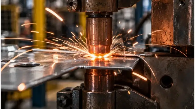
How Electric Resistance Welding Works?
To design a reliable joint, it helps to understand how the weld nugget is formed. Resistance welding relies on internal heat generation and mechanical forging, rather than an open electrical arc.
Current Creates Localized Heat
The process is based on Joule heating, expressed by the formula:
Q = I²Rt
Heat (Q) is generated when a controlled electrical current (I) passes through the natural electrical resistance (R) of the overlapping workpieces over a specific duration (t).
Because the heat generated is proportional to the square of the current, small amperage adjustments create significant changes. The highest electrical resistance occurs at the interface between the two metal sheets, concentrating the heat exactly where the joint needs to form. This is why specifying the correct pre-weld surface treatment—such as removing heavy oxides from aluminum—is a critical DFM step to ensure consistent resistance.
Note that while many resistance welding applications melt the metal to form a fusion nugget, specific processes (like certain butt welds) form solid-state joints through heat and severe plastic deformation.
Pressure Forms and Holds the Nugget
Heat alone will simply burn or blow through the metal. Mechanical pressure applied by the electrodes is mandatory.
This clamping force establishes a stable initial contact between the sheets, controlling the actual contact area before the current begins to flow. During the weld, the pressure contains the molten metal, limiting the amount of expulsion (spatter) that escapes the joint. After the current stops, the electrodes maintain pressure to forge the metal, helping the nugget remain stable while it cools. Both insufficient and excessive pressure will negatively impact the final weld strength.
The Welding Cycle
A standard resistance weld follows a strict, millisecond-level timeline controlled by the machine:
- Squeeze time: The electrodes close and build up the required clamping force on the workpieces.
- Weld time: The current flows through the circuit, generating heat and forming the weld nugget.
- Hold time: The current turns off, but the electrodes remain closed under pressure, allowing the nugget to solidify and cool.
- Off time: The electrodes open, allowing the part to be repositioned for the next weld.
Production Value: For custom enclosures hitting volumes of 1,000+ units, the elimination of manual filler work makes ERW one of the most cost-effective assembly choices. Short cycle times, limited consumables, and straightforward automation make it highly useful for repetitive assemblies.
Spot, Seam, or Projection Welding: What Fits
Selecting the correct resistance welding process depends on the part geometry, the required joint strength, and the production environment.
Spot Welding for Overlapping Sheets
Spot welding is the standard process for joining two or more overlapping metal sheets. It is widely used for sheet metal enclosures, internal brackets, reinforcement plates, and repetitive lap joints. It is highly effective for standard sheet thicknesses ranging from 0.5mm to 3.0mm, though exact limits depend on the material grade and machine capacity.
While efficient, spot welding has specific design constraints. It typically requires physical clearance for the copper electrodes to access both sides of the joint. The process forms individual, localized weld nuggets rather than a continuous seam. Engineers must also account for surface indentations. For cosmetic parts, engineers often specify a flat copper electrode on the visible side and a radiused tip on the back, minimizing indentation to reduce post-weld grinding. Finally, natural electrode wear over a production run will gradually affect the weld nugget size if not monitored.
Seam Welding for Continuous Joints
When a project requires continuous or potentially leak-tight joints, seam welding is usually evaluated.
Instead of static point electrodes, this process uses rotating copper alloy wheels. As the workpieces pass between the wheels, the machine pulses the current to create a series of overlapping spot welds. Seam welding is frequently used for thin-sheet fluid reservoirs, filters, and sealed aluminum boxes. The continuity of the weld depends heavily on the overlap rate of the individual nuggets. If a joint is designed to hold fluids or gases, it must still be subjected to specific leak testing validation after welding.
Projection Welding for Nuts and Studs
Projection welding isolates the welding heat at specific points designated by the part design, rather than relying on the electrode tip shape. It is the primary method for attaching weld nuts, weld studs, cross-wire assemblies, and standoffs to sheet metal bases.
This process utilizes pre-stamped dimples or machined projections on one of the workpieces. These projections concentrate the electrical current, causing them to heat up rapidly and collapse under the electrode’s pressure. This makes it particularly useful for joining parts with varying thicknesses (up to a 3:1 ratio). Because multiple projections can be flattened in a single machine stroke, it significantly reduces cycle times compared to processing individual spots.
Other Common Resistance Welding Processes
| Process | Typical Applications |
| Butt welding | Wire joints, rods, and circular rings |
| Flash butt welding | Railway tracks, wheel rims, tubes, and larger cross-sections |
| Micro resistance welding | Electrical terminals, battery tabs, and miniaturized components |
| Cross-wire welding | Metal wire nets, shelving grids, and wire assemblies |
Why Materials and Coatings Change Weld Quality?
The electrical resistance of the joint is the fundamental variable in this process. Because different alloys and surface conditions conduct electricity differently, parameters that perfectly weld low-carbon steel will fail entirely on aluminum or galvanized sheet.
| Material Type | General Production Difficulty | Key Engineering Challenges |
| Low-carbon steel | Low | Surface contamination (oil/scale) and fit-up gaps |
| Galvanized steel | Medium | Electrode sticking, tip wear, and zinc displacement |
| Stainless steel | Low to Medium | Deep indentation and localized overheating |
| High-strength steel | Medium | Narrow parameter windows and brittle fracture modes |
| Aluminum alloys | High | High thermal conductivity and erratic oxide films |
| Copper alloys | High | Ultra-low electrical resistance and rapid heat dissipation |
| Dissimilar metals | Requires validation | Thermal imbalance and brittle intermetallic phases |
Process Note: These ratings are general starting points. Actual production results depend heavily on the specific material grade, sheet thickness, coating weight, sheet stack configuration, electrode material, and machine capability.
Carbon Steel and Coated Sheet
Standard bare low-carbon steel is the most straightforward material to resistance weld, offering a wide and forgiving parameter window. However, heavy mill scale, rust, or stamping oils will still disrupt electrical contact and cause process instability.
When carbon steel is coated with zinc (galvanized or galvannealed) for corrosion resistance, the process dynamics shift. Zinc melts at a much lower temperature than steel, altering the contact resistance at the interface. Consequently, galvanized steel typically requires 20% to 30% higher welding currents and longer weld times to displace the zinc layer and fuse the underlying steel. Furthermore, molten zinc tends to alloy with the copper electrodes, accelerating tip wear. For advanced high-strength galvanized steels, engineers must also carefully control cooling rates to prevent Liquid Metal Embrittlement (LME).
Stainless and High-Strength Steel
Stainless steel (such as 304 or 316) has a higher electrical resistance and lower thermal conductivity than carbon steel. This means it requires significantly less welding current to generate the necessary heat. However, this high resistance causes heat to concentrate rapidly. If the current or weld time is too high, it leads to severe localized overheating, part distortion, and deep electrode indentation.
High-strength steel (HSS) and advanced high-strength steel (AHSS) present mechanical challenges. Because the material is highly rigid, the machine must apply a much higher electrode clamping force to overcome any minor fit-up gaps before the current flows. The rapid heating and quenching cycle can also create brittle microstructures in HSS. To ensure reliable performance, our engineering team evaluates weld strength and fracture modes (e.g., peel vs. button pull-out) in accordance with ISO 14373 or AWS D8.1 standards.
Aluminum, Copper, and Mixed Metals
Aluminum and copper are difficult to resistance weld because they are excellent conductors of both heat and electricity. When current is applied, the heat dissipates into the surrounding metal rather than concentrating at the joint.
To successfully weld aluminum, the machine must deliver massive, rapid spikes of current to melt the interface before the heat escapes. Additionally, aluminum naturally forms a tough, electrically erratic surface oxide layer that must be strictly managed or chemically removed prior to welding. Copper alloys are even more challenging due to their ultra-low resistance, often requiring specialized refractory metal electrodes (like tungsten or molybdenum) to force the heat generation into the workpiece.
When welding dissimilar metals, the differing melting points and resistivities cause asymmetrical heat balances. The weld nugget tends to form in the metal with the higher electrical resistance, which requires specific transition materials, custom electrode geometries, or thorough trial-weld validation.
How to Design Parts for Resistance Welding?
Resistance welding is highly sensitive to part geometry. In the CAD phase, engineers must design joints that allow physical access for the tooling and ensure the electrical current behaves predictably. This is one of the most critical Design for Manufacturability (DFM) steps.
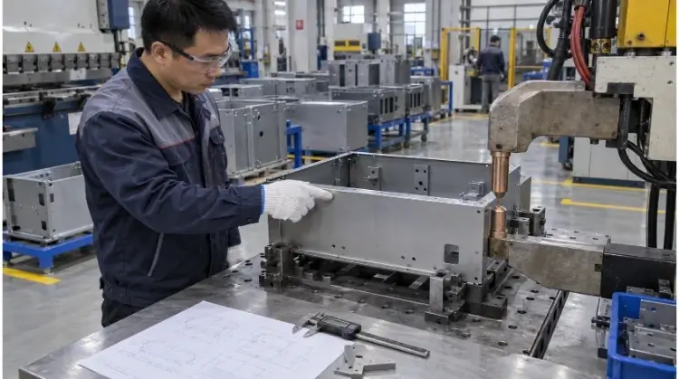
Electrode Access and Flange Geometry
Unlike laser welding which only requires a line of sight, spot and projection welding physically clamp the part. The most common DFM failure is designing a joint where the electrodes cannot physically reach or squarely close on the weld location.
Designers must verify the following:
- Alignment: Upper and lower electrodes must align perfectly on a shared axis.
- Clearance: The electrode shanks and machine arms must not collide with adjacent bend radii, flanges, or hardware.
- Contact Area: The electrode face must make full, flat contact with the sheet. Welding on an angle or a curve will cause immediate expulsion and weak joints.
- Structural Rigidity: The sheet metal flange must be wide enough and rigid enough to withstand the machine’s clamping force without collapsing.
- Deep Cavities: Narrow U-channels or deep enclosures often require specialized, offset electrodes, which can limit the maximum applied force and increase setup tooling costs.
Nugget Size, Pitch, and Edge Distance
The physical dimensions of the joint dictate the strength of the assembly.
If a spot weld is placed too close to the edge of a part, the molten metal will blow out the side (expulsion), leaving a weak joint and creating safety hazards. A standard engineering baseline is to maintain a minimum edge distance of at least two times the weld nugget diameter.
Similarly, welds cannot be placed too close together. If the pitch (spacing) between spots is too tight, the electrical current will take the path of least resistance, traveling through the adjacent, previously completed weld rather than passing through the new joint interface. This phenomenon, known as shunting, results in undersized or non-existent weld nuggets.
| Design Check | Engineering Dependency |
| Weld diameter | Base material, sheet thickness, and electrode face geometry. |
| Edge distance | Required nugget size, edge strength, and expulsion prevention. |
| Weld pitch | Required joint strength and the mitigation of electrical shunting. |
| Flange width | Must accommodate the weld diameter, edge distance, and physical electrode profile. |
| Sheet stack | Maximum number of layers (usually 2-3) and thickness ratios (avoiding ratios greater than 3:1). |
Engineering Support: Not sure if your flange design provides enough electrode clearance or avoids shunting? Submit your 3D CAD files for a free DFM review by the TZR engineering team before finalizing your drawings.
Fit-Up and Cosmetic Surfaces
Because resistance welding uses pressure to forge the joint, any gap between the metal sheets prior to welding will compromise the process. If a portion of the machine’s clamping force is wasted forcing warped parts together, the actual contact pressure at the joint drops, leading to early expulsion and inconsistent heating. Engineers must account for stamping tolerances and bending springback during the design phase.
For parts with high cosmetic requirements, downstream finishing processes must be considered. Resistance welding naturally leaves some degree of surface indentation and localized heat tint. If the assembly will be powder coated, minor indentations may be filled by the paint. However, if the part features brushed stainless steel or requires clear anodizing, the heat-affected zone will alter the material’s grain and chemical structure, resulting in highly visible color variations.
Failing to account for this in the design phase often forces manufacturers to introduce heavy manual grinding post-weld. This labor-intensive rework entirely destroys the cycle-time cost advantages that made resistance welding attractive in the first place.
Shop-Floor Reality: Welding parameters cannot fully compensate for poor part fit-up. If the sheet metal components do not sit flush in the fixture naturally, the resulting weld quality will always be erratic.
Setting Current, Time, and Electrode Force
Establishing a stable production process requires moving beyond the basic Joule heating formula and carefully balancing the machine settings.
Current, Time, and Force Balance
The three primary variables in resistance welding—current, time, and pressure—are strictly interdependent. You cannot adjust one without impacting how the others behave. For instance, increasing the electrode pressure decreases the contact resistance; to maintain the same heat generation, the welding current or time must then be proportionately increased.
| Parameter Status | Probable Result on the Weld |
| Insufficient Current | Undersized weld nugget or no fusion (cold weld). |
| Excessive Current | Severe expulsion (spatter), electrode sticking, and metal burn-through. |
| Insufficient Time | Inadequate heat generation, resulting in a weak joint. |
| Excessive Time | Localized overheating, deep electrode indentation, and rapid tip wear. |
| Insufficient Pressure | Unstable electrical contact leading to immediate surface expulsion. |
| Excessive Pressure | Decreased contact resistance and current density, potentially shrinking the nugget. |
Weld Schedules and Process Windows
Before moving into full production, engineers develop a “weld schedule.” This is a programmed sequence that dictates the exact parameters for every phase of the machine stroke, including squeeze time, weld time, hold time, current level, and electrode force. For thicker materials, this may also include pulse counts.
During setup, technicians map out a weld lobe (or process window). The bottom of this lobe represents the minimum parameters required to form an acceptable nugget; the top represents the limit where excessive heat causes expulsion. The goal of a manufacturing facility is never to find a single “perfect” parameter point, but to center the production schedule safely inside this stable window to absorb normal batch-to-batch material variations.
Equipment Note: While standard AC transformers are still common, modern precision assembly often utilizes Mid-Frequency Direct Current (MFDC) inverter power supplies. These allow for millisecond-level current control and faster adjustment to dynamic resistance changes during the weld.
Electrode Wear and Cooling
Copper electrodes are consumable tools. Over hundreds of welding cycles, the repeated heat and pressure cause the electrode face to flatten and widen—a condition known as “mushrooming.” As the face area increases, the current density drops, leading to smaller and weaker weld nuggets. On coated metals like galvanized steel, the electrode will also pick up zinc alloys, further degrading performance.
To maintain process stability, production lines must establish:
- Tip dressing frequency (reshaping the copper profile)
- Absolute replacement limits for electrodes
- Cooling-water flow checks (inadequate cooling accelerates wear exponentially)
- Weld-count records tied to the machine
- Post-dressing destructive verification
Shop-Floor Safety: Protect operators from electrode pinch points, flying metal, hot parts, coating fumes, and stored electrical energy. Disconnect and discharge equipment before maintenance.
Why Resistance Welds Fail During Production?
When a resistance weld fails on the floor, the immediate reaction of an inexperienced operator is often to simply increase the current. However, root-cause diagnostics require looking at the physical symptoms first.
Weak or Undersized Nuggets
If a tear-down reveals a small or non-existent nugget, the root cause is a lack of concentrated heat. This can be caused by insufficient current or weld time, but it is equally likely to be caused by excessive electrode pressure, an oversized (mushroomed) electrode tip, surface oil/scale, or electrical shunting to an adjacent weld.
Crucial Reminder: A visible electrode mark on the surface of the sheet does not prove that a sound weld nugget formed inside the joint.
Expulsion, Indentation, and Sticking
Visual defects are immediate indicators of an imbalanced process.
| Visible Defect | Common Causes | First Items to Check |
| Expulsion (Spatter) | Current too high, pressure too low, or significant gaps between sheets. | Current settings, clamping force, and part fit-up. |
| Deep Indentation | Electrode face too small, excessive heat, or excessive pressure. | Electrode tip condition and weld time. |
| Electrode Sticking | Coating buildup (zinc/aluminum), inadequate cooling, or overheating. | Electrode cleanliness and water cooling flow. |
| Surface Burning | Surface contamination or poor initial electrode contact. | Material cleanliness and tip alignment. |
| Part Distortion | Incorrect weld sequencing or inadequate fixture support. | Weld order, total heat input, and fixture rigidity. |
The Cost of Downstream Defects: Defects discovered during final assembly, anodizing, or powder coating lead to expensive scrapped parts and delayed shipments. Investing in proper DFM and fixture setup upfront costs a fraction of addressing batch failures downstream.
Shunting, Misalignment, and Poor Fit-Up
Physical alignment issues frequently masquerade as parameter failures. If upper and lower electrodes are misaligned, the weld nugget will form irregularly and off-center. If the fixture lacks rigidity, repeatable positioning is impossible.
Diagnostic Case Study:
During the assembly of a batch of 1.5mm stainless steel enclosures, an operator noticed that the third and fourth spot welds in a row were consistently failing peel tests, despite the first two welds passing easily. Rather than adjusting the machine’s current, the engineering team identified the issue as electrical shunting. The CAD design had placed the welds too close together. The current for the third weld was bypassing the intended joint and flowing back through the adjacent, highly conductive first and second welds. The solution was adjusting the weld sequence and increasing the pitch on the engineering drawing, completely resolving the defect without touching the machine parameters.
How to Inspect and Verify Weld Quality?
Because the actual weld is hidden between two pieces of metal, visual inspection is never enough. Quality must be verified through a combination of destructive testing and real-time monitoring.
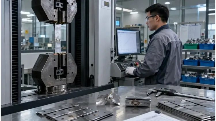
Destructive Weld Tests
Destructive testing is mandatory during setup, after electrode dressing, and at scheduled intervals during the production run.
- Peel Test: The most common shop-floor test. The overlapping sheets are torn apart to verify that a solid metal “button” pulls out from one sheet, proving the weld is stronger than the base metal.
- Chisel Test: A chisel is driven between the sheets next to the weld to check for brittle fracture or separation.
- Tensile-Shear Test: Conducted in a lab using a universal testing machine to measure the exact force required to break the joint in shear.
- Cross-Tension Test: Measures the joint’s resistance to pulling forces perpendicular to the sheet.
- Macro-Etch Examination: The weld is cut in half, polished, and chemically etched to measure the exact nugget diameter and penetration depth under a microscope.
Inspection and Process Monitoring
Non-destructive monitoring provides continuous data between destructive teardowns. This includes verifying weld locations, measuring maximum surface indentation limits, and checking for external cracks. Advanced equipment monitors current variations, voltage drops, dynamic resistance, and electrode displacement in real-time.
Quality Control Note: Process data can reveal drift, but it does not automatically prove weld strength. It must always be calibrated against physical teardown data.
Acceptance Criteria and Control Plans
Before a manufacturing run begins, the buyer and the factory must agree on the acceptance criteria. Following quality frameworks such as ISO 9001 or specific automotive guidelines, a robust control plan should define:
- Minimum acceptable weld nugget size
- Minimum joint strength (if load-bearing)
- Acceptable fracture modes (e.g., full button pull-out required)
- Maximum allowable surface indentation (critical for cosmetic parts)
- Strict limits on cracks or internal porosity
- Leak testing requirements (for seam welding)
- Destructive sampling frequency (e.g., every 500 parts or every shift)
Conclusion
Resistance welding is fast and repeatable when material, joint geometry, electrode access, and process control are considered together. Machine settings alone cannot correct an unsuitable joint design.
Send us your drawings, material grade, sheet thickness, and expected volume. The engineering team at TZR can review your weld locations, electrode access, appearance requirements, and inspection plans before quotation, ensuring your sheet metal enclosures are optimized for structural integrity and pristine surface finishing from day one.