
 English
  Spanish
  German
  Russian
  Italian
  French
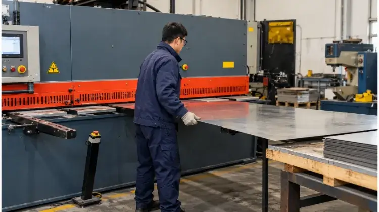
Sheet metal shearing is a cold, chipless metal fabrication process that uses opposing blades to cut sheet metal into straight blanks. It is highly cost-effective for high-volume straight-line cuts, but requires precise blade clearance to prevent edge deformation and work hardening.
For design engineers and procurement managers, shearing is often the fastest first step in a fabrication routing. However, specifying the right blanking process—and avoiding downstream assembly failures—depends strictly on your material capabilities, part geometry, and edge requirements.
Before committing to a sheared blank, use this quick decision matrix to evaluate if the process fits your production intent:
| Part Requirement | Key Assessment Area |
| Rectangular panels, straight trimming, standard strips | Shearing capacity and dimensional limits |
| Complex contours, internal holes, and slots | Laser cutting, punching, or combined operations |
| Long narrow strips, strict flatness | Twist and bow risks |
| Cosmetic edges, handled parts, subsequent forming | Edge conditioning and surface protection |
How Shearing Separates Metal and Forms Edges?
To understand the tolerances and physical limitations of a sheared blank, you must first look at how the metal separates during the cutting cycle.
Cutting Action
In a standard guillotine shear, the upper blade descends past a fixed lower blade. As the blades make contact, the metal undergoes plastic deformation. The blades penetrate the sheet until the internal stress exceeds the material’s shear strength, causing the metal to fracture and separate.
This process is strictly for straight-line cuts across a sheet. It differs fundamentally from coil slitting (which uses continuous rotary blades), punching (which cuts closed contours using a shaped punch and die), and blanking (which stamps a full 2D shape in one stroke).
Edge Zones
A sheared edge is not a perfectly flat, uniform surface. A cross-section of a sheared cut reveals four distinct zones:
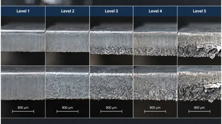
- Rollover: The rounded top edge where the upper blade first presses into the material.
- Burnished Zone: A smooth, vertical, and highly polished band created as the blade physically penetrates and slides against the metal.
- Fracture Zone: A rougher, slightly angled surface where the material finally breaks apart.
- Burr: A sharp, projecting lip at the bottom edge caused by the final material separation.
The natural fracture zone and burr mean a standard sheared edge is usually not acceptable for handled areas or cosmetic surfaces without secondary finishing.
Process Limits
Industrial shearing machines are designed exclusively for straight cuts; they cannot produce internal slots, angled notches, or curved profiles.
Shearing is often specified because it is a cold, chipless cutting method. “Chipless” means no material is lost to a cutting kerf (unlike a saw or laser), and “cold” means there is no heat-affected zone (HAZ) altering the metal’s grain structure.
However, this does not mean the process is free from mechanical stress. The high tonnage required to fracture the metal induces localized work hardening along the cut line. If this sheared edge is positioned on the outside radius of a subsequent tight bend, it is highly susceptible to micro-cracking. For heavy-duty formed parts, this edge usually requires a secondary shaving or grinding operation to restore ductility.
When Shearing Fits Your Material and Geometry?
Shearing is highly efficient, but it has strict boundaries regarding the dimensions it can produce and the materials it can process without causing severe part distortion.
Blank Geometry
Shearing works best for rectangular panels, square blanks, and wide strips. It is usually the primary blanking operation, creating the base dimension before the part moves to a press brake or CNC machine.
When cutting long, narrow strips, the physical mechanics of the shear blade often cause the cut piece to deform. If the width of the strip is less than 10 to 15 times the thickness of the material, the mechanical force is highly likely to cause the strip to twist (corkscrew) or bow (curve upward). In these cases, shearing may not be viable if strict flatness is required.
💡 Factory Note: When nesting parts, remember that shearing requires the blade to traverse the entire sheet. You cannot stop a shear cut halfway through a plate. If your nest has interlocking L-shapes or complex nested profiles, laser cutting will yield better material utilization than shearing.
Material Capacity
Machine capacity depends strictly on the material grade, temper, and thickness. Equipment ratings are typically based on mild steel with a tensile strength of around 400-450 N/mm². Because the required cutting force correlates directly with the material’s shear strength, a shear rated for 6mm mild steel can generally only process 3mm or 4mm stainless steel (which often exceeds 600 N/mm² tensile strength).
The table below outlines typical capacity limits for standard industrial guillotine shears.
| Material & State | Proven Thickness Limit | Cut Length Limit | Process Restrictions |
| Mild Steel (e.g., A36, Q235) | Up to 12mm | Up to 3000mm | Standard capacity baseline. |
| Stainless Steel (e.g., 304, 316) | Up to 6mm | Up to 3000mm | Requires a 50% capacity reduction due to higher shear strength. |
| Aluminum (e.g., 5052-H32) | Up to 15mm | Up to 3000mm | Soft surface is susceptible to scratching and marking from heavy hydraulic hold-down clamps. |
Note: The machine’s structural rigidity, blade sharpness, and hydraulic hold-down force also affect the actual maximum capacity on the shop floor.
Cutting Alternatives
Process selection depends on geometry, edge requirements, and batch size.
Shearing is the most efficient method for straight external profiles, often completing a cut in seconds. It becomes highly cost-effective at volume. Laser cutting is required for complex contours, internal features, or when the mechanical stress of shearing is unacceptable for the material. CNC punching works well for parts needing multiple standard holes, louvers, or embossments.
If a part requires a straight external profile but features complex internal holes, a common production routing is to shear the blank first for speed and high material yield, then move the blank to a punch press or laser to process the internal features.
How Machine Settings Affect Burrs and Distortion?
A sheared edge is not solely determined by the material properties; it is heavily influenced by how the machine is calibrated for that specific cut. Edge quality and blank flatness require balancing three primary mechanical settings.
Blade Clearance
Blade clearance is the horizontal gap between the upper and lower cutting blades, and it dictates how the material fractures. Optimal clearance ensures that the micro-fractures propagating from the upper and lower blades meet perfectly in the center of the material thickness, creating a clean break.
If the clearance is too tight, the micro-fractures miss each other. The blades must force their way through, resulting in a “secondary shear” (a double-cut appearance) and accelerated tool wear. If the clearance is too loose, the metal bends and folds between the blades before fracturing, causing severe edge rollover and heavy, jagged burrs.
Clearance settings must match the material grade and thickness. While a common baseline is setting the gap to 5% to 10% of the material thickness, this is not a universal rule. For example, a 6mm aluminum plate requires a tighter blade clearance than a 6mm stainless steel plate on the same machine to achieve a clean fracture zone. The exact parameter is typically confirmed via a trial cut.
Rake Angle
The rake angle is the incline of the upper blade relative to the fixed lower blade. Industrial shears typically allow rake angle adjustments between 0.5° and 3.0°.
Increasing the rake angle reduces the length of the blade contacting the metal at any single moment. This lowers the total machine tonnage required to make the cut, allowing a shear to cut thicker plates. However, a high rake angle forces the cutoff piece to bend sharply downwards during the stroke, significantly increasing the risk of twisting and bowing—especially on long, narrow strips.
Decreasing the angle towards 0.5° keeps the blank flatter, but it demands exponentially more hydraulic cutting force. Adjusting the rake angle is a strict trade-off between machine capacity and part distortion; it is not a unified fix for all flatness issues.
Blade Condition and Hold-Downs
Edge quality depends entirely on the sheet remaining perfectly stationary during the blade stroke.
Hydraulic hold-down pads clamp the sheet to the machine bed before the blade descends. If the hold-down pressure is insufficient, the material will tilt or shift as the blade makes contact. This shifting artificially changes the effective blade clearance during the cut, resulting in cambered cuts and inconsistent burrs. Conversely, applying excessive hold-down pressure on soft materials like 5052 aluminum can leave deep clamp indentations (marring) on the surface, which is unacceptable for cosmetic panels.
Additionally, cut quality cannot be fixed by clearance adjustments alone if the tooling is compromised. Dull or chipped blades will crush the material rather than shear it, widening the burnished zone and leaving heavy burrs.
How to Specify and Verify Shearing Quality?
To prevent disputes between procurement and production, shearing quality must be specified using measurable engineering terms rather than subjective adjectives like “smooth” or “high precision.”
Dimensional Requirements
A sheared blank is evaluated on three dimensional metrics: length/width tolerance, straightness, and squareness.
Do not confuse machine positioning repeatability with actual part tolerance. A CNC backgauge may boast a positioning repeatability of ±0.05mm, but the actual sheared blank tolerance is dictated by material behavior during the fracture. For a 4mm 5052 aluminum plate measuring 1000mm x 500mm, a realistic finished part tolerance is typically ±0.3mm to ±0.5mm.
Squareness (perpendicularity between adjacent sides) relies heavily on the operator squaring the sheet against the machine’s squaring arm. Any tolerance callout on the drawing must account for the material thickness and the overall dimensions of the blank.
Flatness and Edges
The high mechanical stress of shearing often causes the cutoff piece to deform. These deformations fall into three distinct categories:
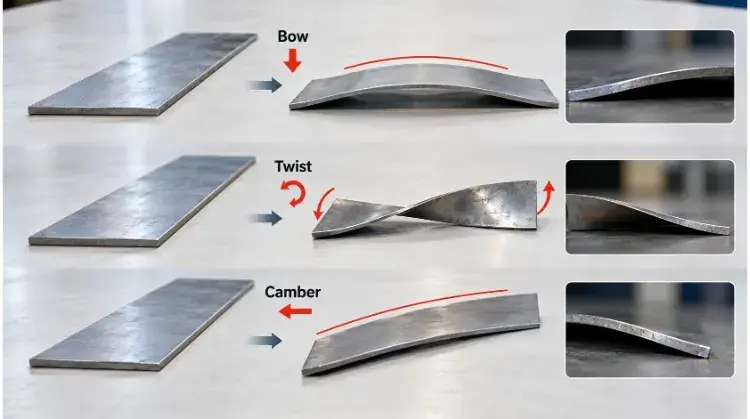
- Twist: The strip rotates along its longitudinal axis, resembling a corkscrew.
- Bow: The strip curves upward or downward along its flat surface.
- Camber: The strip curves left or right along its sheared edge, deviating from a true straight line.
💡 Engineer’s Note: Distortion is heavily influenced by the raw material’s rolling grain direction. Shearing parallel to the grain often produces significantly more twist than shearing perpendicular to it. When planning the sheet nest, engineers must balance material yield against grain-induced distortion.
Flatness must be measured in a “free state.” This means placing the part on a calibrated inspection table without applying any clamps or weights to force it flat, and measuring the highest deviation from the surface.
For edge quality, avoid specifying “clean edges.” Instead, explicitly state the acceptable burr height (e.g., “Maximum burr 0.1mm”) or mandate a secondary operation (e.g., “Break all sharp edges” or “Tumble deburr”).
Production Checks
Quality verification begins with a First Article Inspection (FAI) before running the full batch. The first sheared blank is measured for dimensions, squareness, and free-state flatness. Once approved, production can proceed with random sampling (e.g., measuring one part out of every 50). A new FAI is strictly required if the material heat lot changes, or if the operator adjusts the blade clearance.
When defects occur, they are rarely caused by a single parameter. Use the troubleshooting table below to identify and verify the root cause logically.
| Defect Observation | Potential Causes | Verification Sequence |
| Heavy Burr on Bottom Edge | Blade clearance too large; Dull or chipped blades. | 1. Measure clearance using a feeler gauge and adjust. 2. Inspect blade edge for physical wear. |
| Secondary Shear (Double Cut) | Blade clearance too tight. | 1. Increase blade clearance based on material thickness and trial cut. |
| Camber (Curved Edge) | Insufficient hold-down pressure; Internal material stress. | 1. Check hydraulic hold-down pressure. 2. Verify if the raw coil had residual stress before uncoiling. |
| Twist or Bow | Rake angle too high; Strip width too narrow (less than 10x thickness); Shearing parallel to grain. | 1. Decrease rake angle (if machine tonnage allows). 2. Check grain direction. 3. Evaluate if laser cutting is required for this geometry. |
| Out of Square | Poor operator alignment; Squaring arm out of calibration. | 1. Check operator feeding method against the stops. 2. Recalibrate the squaring arm against the blade. |
How to Design Blanks for Later Operations?
A sheared piece of metal is rarely the final product. It is a blank—a raw geometric starting point for downstream operations like bending, stamping, machining, or welding. To prevent manufacturing failures, engineers must design the blank to survive these subsequent steps.
Blank Dimensions
A sheared blank dimension is not automatically the finished part dimension. If the edge requires secondary CNC milling to achieve a tight sealing tolerance or a perfectly vertical wall, you must explicitly add a machining allowance to the sheared blank size (typically 1.0mm to 2.0mm per edge).
When designing parts with internal features, evaluate the sequence of operations. The downward compressive force of the shear blade displaces metal. If an existing hole or slot is located too close to the shear line, the mechanical pressure will distort the hole into an oval. A standard baseline is keeping holes at least 1.5 to 2 times the material thickness away from the cut line. To completely avoid this risk, specify that critical holes must be punched or laser-cut after the shearing operation.
Edge Preparation
Depending on the final assembly, the sheared edge will require specific conditioning.
Deburring is a standard operation (often done via tumbling or dual-action sanding) that removes the sharp physical lip on the bottom of the cut. However, deburring does not eliminate localized work hardening. If the sheared edge is placed on the outside radius of a heavy bend, or if the edge requires extensive flanging, the altered micro-structure is prone to cracking. For severe forming operations, specify edge shaving or grinding to physically remove the hardened fracture zone and restore the metal’s ductility.
If the part is to be TIG or MIG welded, the burnished zone must be clean. Standard structural welding codes (like AWS D1.1) explicitly require edges to be free of burrs, rust, and cutting fluids to prevent porosity in the weld. Drawing callouts should explicitly state: “Edges must be free of burrs and cutting fluids prior to welding.”
Surface Protection
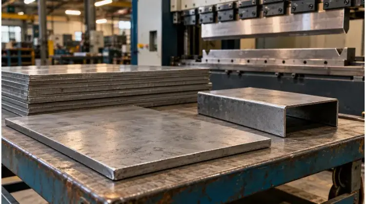
Industrial shearing is a heavy, mechanical process. The material is dragged across a steel machine bed, clamped by high-pressure hydraulic cylinders, and drops onto a stacking cart.
For cosmetic panels, brushed stainless steel, or pre-painted stock, surface marring is a high risk. Engineers must specify the use of PVC protective film (often laser film or standard peeling film) before the material is cut. Additionally, call out the surface requirement on the drawing (e.g., “Cosmetic Face – No clamp marks or scratches allowed”) so the factory knows to equip the hydraulic hold-downs with urethane protective covers.
💡 Factory Case: Edge Cracking on 5052-H32 Aluminum Panels
- Requirement: A sheared 3mm aluminum blank intended for a 90-degree press brake operation to form an electronics enclosure.
- Issue: During the first article inspection, the outside radius of the bend cracked consistently.
- Adjustment: The factory identified that the blank was being sheared parallel to the material’s grain direction, and the work-hardened shear edge was taking the maximum tension during the bend. The nesting layout was rotated 90 degrees so the bend was perpendicular to the grain. The edge was lightly sanded to remove the micro-fractures.
- Result: Zero cracking on the remaining production batch, with full structural integrity maintained.
What Determines the Total Cost of Shearing?
Shearing is inherently cheaper than laser cutting for straight profiles, but quotes from different fabricators can vary significantly based on how they calculate setup, yield, and secondary processing.
Setup and Handling
The actual shearing stroke takes less than two seconds. The true cost of the operation lies in the setup and material handling.
Before the first cut is made, the operator must program the CNC backgauge, calibrate the blade clearance for the specific material thickness, adjust the rake angle, and use a forklift to load the raw sheet onto the bed. During production, the operator manually feeds, rotates, and offloads the blanks.
Because of this fixed setup time, shearing is highly sensitive to batch size. Distributing a 30-minute machine setup over 10 parts results in a high cost-per-part. Distributing that same setup over 2,000 parts drops the shearing cost to pennies per blank. There is no strict volume threshold, but shearing becomes significantly more cost-effective as batch quantities scale.
Yield and Finishing
Cost efficiency relies heavily on material yield. A sheared part is only economical if the nesting layout maximizes the use of the standard sheet and minimizes scrap.
Unlike laser cutting, which can nest interlocking complex shapes like puzzle pieces, shearing is bound by the guillotine constraint—every cut must travel perfectly straight from one edge of the material to the other. If your part dimensions do not allow for collinear nesting, material yield will drop, and laser cutting might actually become the more economical choice.
Furthermore, evaluate the cost per qualified part. If a fabricator submits a rock-bottom price for shearing but leaves you with heavily bowed parts covered in burrs, the internal cost to flatten (roller leveling) and deburr those parts will erase any initial savings. When comparing quotes, ensure all vendors are quoting to the exact same flatness and edge finishing requirements.
Quote Requirements
To receive an accurate and actionable quote without excessive back-and-forth communication, provide your manufacturing partner with the following data:
- Material Specifications: Exact grade (e.g., 304L, 5052-H32), thickness, and any surface requirements (e.g., #4 brushed, PVC one side).
- Drawings: PDF and CAD files with critical dimensions, free-state flatness requirements, explicit edge conditions, and grain direction constraints (if the part requires heavy downstream bending).
- Downstream Intent: State what will happen to the blank next (e.g., “Blank will be CNC milled on all four sides – leave 2mm allowance” or “Will undergo deep drawing”).
- Logistics: Total order quantity, expected lead time, and packaging requirements (e.g., rust-inhibitor paper, banded to custom pallets).
Send us your drawing, material specification, and quantity. Our team can review suitable cutting options and identify the edge finishing and secondary operations your part requires.