
 English
  Spanish
  German
  Russian
  Italian
  French
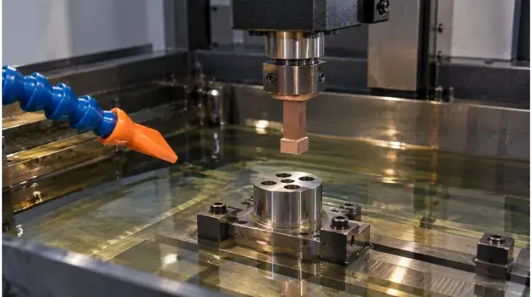
Sinker EDM (Electrical Discharge Machining) is a non-contact manufacturing process that uses controlled electrical sparks between a shaped electrode and a conductive workpiece to erode material. It is primarily used to machine complex blind cavities, sharp internal corners, and hardened metals that traditional CNC milling cannot process.
However, because it relies on thermal erosion rather than physical cutting, it operates much slower than conventional machining. For engineers and procurement teams, the challenge isn’t just understanding how the sparks work—it’s knowing when a complex geometry justifies the higher cycle times and custom electrode tooling costs.
Before evaluating tolerance limits or cost structures, use the quick-reference table below to confirm if your component actually requires this process.
| Feature Requirement | Primary Process to Evaluate |
| Open, easily accessible cavities | CNC Milling |
| Through-profiles or irregular through-holes | Wire EDM |
| Complex blind cavities in hardened materials | Sinker EDM |
| Mostly accessible areas with isolated hard-to-reach details | CNC Milling + Sinker EDM |
How Sinker EDM Forms Cavities Without Cutting Contact
To specify tolerances and manage costs, it is necessary to understand how the cavity is actually formed. The process relies entirely on thermal erosion, meaning the tool and the workpiece never physically touch.
Shaped Electrodes
The basic geometry of the cavity is determined by the electrode. As the machine lowers the electrode toward the workpiece, its inverse shape is transferred into the metal.
The most common electrode materials are graphite and copper. Graphite is generally faster to machine and resists heat well, making it standard for most tooling applications. Copper, on the other hand, wears more predictably and produces finer surface finishes.
Spark Gap
Material removal occurs through thousands of controlled sparks per second. A servomechanism maintains a precise distance—typically between 0.01 mm and 0.1 mm—between the electrode and the workpiece.
Because the sparks must jump this gap to vaporize the metal, the resulting cavity is always slightly larger than the electrode itself. To account for this overcut, engineers must machine the electrodes undersized so the final cavity matches the print dimensions.
Dielectric Fluid
The entire operation takes place submerged in a dielectric fluid, usually a hydrocarbon oil. This fluid acts as an insulator until the exact voltage threshold is reached, cools the workpiece, and flushes away the vaporized metal particles.
While the process applies zero mechanical cutting force, material removal relies on intense localized heat. This thermal action alters the microstructure of the machined surface, leaving a hard, brittle recast layer (white layer) and a heat-affected zone (HAZ). If the part is subject to high fatigue stress, this layer usually requires control or removal through post-polishing or chemical etching.
Choose Sinker EDM for the Right Features
Deciding to use sinker EDM should be based on geometric necessity and material conditions rather than preference. It is a slow process, so it is usually reserved for features that conventional machining cannot process efficiently.
Cavity Geometry
Sinker EDM works well for features that restrict milling tool access. Typical applications include thin ribs in injection molds, internal corner radii under 0.5 mm, and deep blind cavities where the length-to-diameter (L/D) ratio exceeds 10:1.
However, the process still has strict geometric limits, as the electrode must have a clear linear path to enter and exit the workpiece. Furthermore, if a cavity is too deep and narrow, flushing becomes restricted. Eroded particles accumulate and the spark destabilizes, which leads to dimensional variations.
Material Condition
The only strict material requirement for EDM is electrical conductivity. The process machines hardened tool steels, titanium, and carbide exactly the same way it machines softer metals.
This allows manufacturers to fully heat-treat components (e.g., to 50+ HRC) before machining the final features. Machining in the hardened state completely eliminates the risk of warping or dimensional distortion caused by the thermal cycling of the hardening process.
Process Selection
Choosing between sinker EDM, wire EDM, and CNC milling usually depends on access and cycle time. Wire EDM is standard for through-holes, while CNC milling remains the most cost-effective method for bulk material removal.
In practice, these methods are frequently combined. For a complex mold insert, a standard manufacturing workflow involves roughing and finishing the accessible open areas with a CNC mill, heat-treating the steel block, and then using sinker EDM only for the deep corners and thin ribs where milling tools cannot reach.
Design Cavities for Access and Dimensional Control
Even when a feature requires sinker EDM, its design heavily influences the final cost and dimensional accuracy. Modifying a geometry slightly can often eliminate the need for complex electrode strategies.
Electrode Access
Sinker EDM operates primarily on a straight-line axis (usually the Z-axis). The graphite or copper electrode must be able to plunge into the workpiece and retract without physical interference.
When a design includes undercuts, side-wall features, or obstructed areas, a single straight plunge is impossible. These geometries require the supplier to use split electrodes, multi-axis EDM capabilities, or multiple workpiece setups, all of which directly increase tooling costs and lead times.
Depth and Flushing
A stable EDM process relies on the continuous flushing of vaporized debris out of the spark gap. In deep, narrow cavities or blind slots, fresh dielectric fluid struggles to reach the bottom, and eroded particles get trapped.
Trapped debris causes secondary sparking along the cavity walls. This destabilizes the process, causing “bell-mouthed” cavity shapes rather than straight walls. To prevent this in deep slots, the machine must use frequent peck cycles (jump cycles) to physically pump fluid into the gap, which drastically increases the total machining time.
Corners and Wear
Electrical sparks naturally erode the sharpest points of an electrode first. Because of this localized electrode wear ratio, it is physically impossible to machine a true zero-radius internal corner using sinker EDM.
To maintain tight tolerances on sharp features, suppliers must divide the work. A roughing electrode removes the bulk of the material, while one or more finishing electrodes clean up the corners. Relaxing the internal radius on non-critical corners (e.g., allowing R0.1 to R0.2 mm) significantly reduces the number of finishing electrodes required, cutting both tooling costs and machining time.
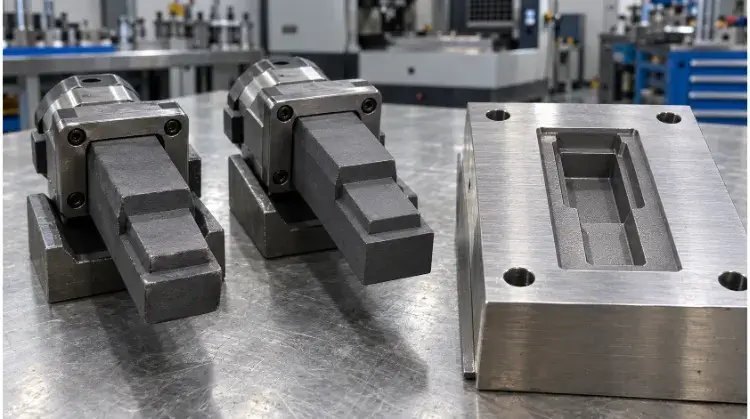
Specify Tolerances and Surface Quality Before Machining
Misalignment between engineering expectations and factory deliverables often happens during the inspection phase. Quality targets must be written as actionable, measurable requirements before machining begins.
Dimensional Tolerances
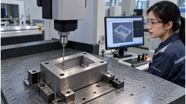
Precision in EDM is heavily dependent on how the part is fixtured and measured. Engineering prints must clearly define the inspection datums for CMM (Coordinate Measuring Machine) verification and explicitly separate the tolerances for cavity width, depth, and true position.
It is also critical to specify the exact stage at which dimensions will be verified. If a cavity requires post-EDM manual polishing to remove the recast layer, the dimensional inspection must clearly account for the material removed during that secondary operation.
Surface Roughness
Sinker EDM leaves a distinct, uniform matte texture composed of microscopic overlapping craters. A high-energy roughing pass leaves a heavily pitted surface, while low-amperage finishing passes can achieve a very fine, smooth finish.
Achieving a low surface roughness directly increases the EDM cycle time, as it requires thousands of slower, low-energy sparks. To control costs, specify fine finishes (e.g., VDI 12 / Ra 0.4µm) only on functional surfaces—such as sealing faces or mold cavities—and allow standard rough EDM finishes (e.g., VDI 30 / Ra 3.2µm) on non-critical clearances.
Surface Integrity
The thermal nature of EDM creates a recast layer (white layer), a heat-affected zone (HAZ), and potential micro-cracking on the machined surface.
A low surface roughness reading does not guarantee that the surface integrity is acceptable. For highly stressed components in aerospace or medical applications, engineers must explicitly limit the acceptable depth of the recast layer and define the required verification methods, such as metallurgical cross-sectioning or chemical etching records.
Understand What Drives EDM Cost and Lead Time
Procurement teams are often surprised by the cost of sinker EDM. Understanding how these costs are structured helps identify where design adjustments can yield the highest savings.
Electrode Costs
The largest hidden cost in sinker EDM is the preliminary manufacturing required to create the tools. Every quote includes the engineering time to design the electrodes, the CNC milling time to cut them from raw graphite or copper, and the CMM time to verify their dimensions before they ever touch the EDM machine.
Complex cavities require a series of electrodes—often one for roughing and two for finishing—which multiplies this tooling cost. However, factories utilizing standardized zero-point pallet systems (such as EROWA or System 3R) can seamlessly transfer electrodes between the CNC mill, the CMM, and the EDM machine in seconds without manual indicating. This drastically reduces setup costs and preserves accuracy for repeat orders.
Machining Time
Sinker EDM is inherently slow, and machine time is driven heavily by cavity depth, flushing conditions, and surface finish requirements. Removing bulk material and achieving a fine surface finish (e.g., VDI 12) requires thousands of slow, low-energy sparks, which extends cycle times exponentially.
It is also important to separate machine cycle time from order lead time. Even if a factory utilizes automated lights-out manufacturing to run the EDM overnight, the total lead time must still account for electrode manufacturing, queuing, manual setups, and post-machining polishing.
Design Tradeoffs
Minor design adjustments often eliminate the need for expensive secondary electrodes. For example, relaxing a non-critical internal corner radius from R0.05 mm to R0.2 mm can eliminate a dedicated finishing electrode entirely.
Similarly, confining tight surface roughness requirements strictly to functional areas allows the supplier to burn the rest of the cavity at higher, more efficient energy settings. While exact savings depend on the specific geometry, relaxing non-functional constraints always reduces both tooling costs and machining time.
Prepare Requirements and Verify Your EDM Supplier
To get an accurate quote and ensure the factory can actually deliver the required precision, you must provide unambiguous data and ask specific process questions.
Quote Requirements
A reliable quote requires both a 3D CAD model and a fully dimensioned 2D drawing. The 2D drawing must explicitly state the material hardness (e.g., HRC 52), inspection datums, specific surface finish zones, and any required post-processing.
Leaving tolerances or surface finish requirements open to interpretation forces the supplier to make assumptions. Most suppliers will either inflate the quote to cover unknown risks or quote the cheapest, lowest-quality method to win the job.
Process Evidence
Evaluate a supplier based on their machining strategy, not just their equipment list. Ask the engineering team to explain their electrode sequence, how they plan to transfer datums between the milling center and the EDM, and their flushing plan for deep features.
While premium machine brands (e.g., Makino, GF Machining Solutions) and robotic electrode changers are strong indicators of a capable facility, they cannot compensate for poor electrode design or unstable flushing strategies.
Acceptance Plan
Agree on exactly how the features will be measured before issuing the purchase order. Deep, narrow slots are notoriously difficult to inspect, as standard CMM ruby probes simply cannot fit inside.
The measurement method must be established early—whether relying on custom pin gauges, or using casting compounds (like ReproRubber) to replicate the cavity and measuring the mold on an optical comparator (vision system). Confirm the First Article Inspection (FAI) process, define how dimensional deviations will be handled, and ensure the supplier has a clear communication protocol if an electrode needs to be remade mid-production.
Ready to evaluate your component? Submit your 3D models and drawings to our engineering team for a comprehensive DFM review and sinker EDM assessment.