
 English
 Spanish
 German
 Russian
 Italian
 French

A press fit tolerance is the allowable dimensional variance between a slightly oversized shaft and an undersized hole. By controlling this specific interference range, engineers ensure the mating parts generate enough elastic contact pressure to remain securely joined without mechanical fasteners.
However, specifying this tolerance is a high-stakes balancing act. If the interference is too small, the joint will slip under load; if it is too large, the pressing process can fracture the components. A miscalculated fit doesn’t just fail in service—it leads to scrapped parts and jammed hydraulic presses on the shop floor, driving up hidden manufacturing costs.
This article explains how to move beyond basic ISO charts. We will break down how to calculate true interference ranges, adjust for real-world variables like surface finish and operating temperature, and verify your assemblies for consistent manufacturing.
Key Takeaways
- Mechanism: Press fits rely on controlled material deformation (interference) to generate friction.
- Design Variables: The correct tolerance depends heavily on material stiffness, wall thickness, and thermal expansion.
- Manufacturing Reality: Standard ISO charts only provide nominal limits; they do not account for surface roughness (Ra) or plating thicknesses that often ruin a fit during assembly.
Understand Press Fit Tolerances and ISO Charts
To specify a press fit correctly, you need to understand how fit relationships, alphanumeric tolerance codes, and standard charts translate into physical dimensions on the shop floor.
Fit Types
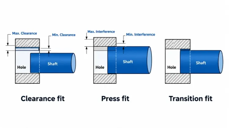
Mechanical fits are generally categorized into three types based on the resulting clearance or interference between the mating parts.
| Fit Type | Description | Resulting Condition |
| Clearance Fit | The shaft is always smaller than the hole. | Parts slide or rotate freely. |
| Transition Fit | The tolerance zones overlap. | May result in either a slight clearance or slight interference. |
| Interference (Press) Fit | The shaft is always larger than the hole. | Requires force or thermal expansion to assemble. |
In an interference fit, the external dimension of the male component (shaft) is deliberately machined larger than the internal dimension of the female component (hole). When forced together, both parts undergo slight elastic deformation. The shaft compresses, and the hole expands. The material’s natural resistance to this deformation creates contact pressure, generating the friction necessary to hold the parts together. Throughout this guide, this dimensional overlap is referred to as diametral interference.
Tolerance Bands
A standard tolerance designation (such as H7/p6) consists of three primary elements:
- Basic Size (Nominal): The target diameter for both parts (e.g., 30 mm).
- Tolerance Position: Indicated by a letter, defining where the tolerance zone sits relative to the basic size. Uppercase letters (e.g., H) refer to the hole; lowercase letters (e.g., p) refer to the shaft.
- Tolerance Width (IT Grade): Indicated by a number (e.g., 7 or 6), representing the acceptable size variance.
Most machine shops prefer the hole-basis system (using an “H” tolerance for the bore). In this system, the minimum allowable hole diameter is exactly the basic size. Because precise internal bores are typically finished using fixed-size tools like reamers or broaches, it is generally more cost-effective to standardize the hole size and achieve the required interference by adjusting the shaft’s outer diameter on a CNC lathe.
Important Note on Tighter Tolerances: Tightening a tolerance band (e.g., moving from an IT7 to an IT5 grade) reduces dimensional variance across a batch, but it does not automatically increase the amount of interference or joint strength. Furthermore, tightening tolerances exponentially increases machining costs, as it often forces a supplier to move from standard CNC turning to secondary operations like cylindrical grinding or honing.
ISO Fit Charts
ISO 286 provides standardized tables that define the upper and lower deviations for various fit combinations. Below is a simplified reference for common hole-basis interference fits.
Standard Fits (ISO 286 – Hole Basis)(Deviations are shown in micrometers, µm. 1 µm = 0.001 mm)
| Basic Size Range (mm) | Hole H7 (Upper/Lower) | Shaft p6 (Upper/Lower) | Shaft s6 (Upper/Lower) |
| Over 10 to 18 | +18 / 0 | +29 / +18 | +39 / +28 |
| Over 18 to 30 | +21 / 0 | +35 / +22 | +48 / +35 |
| Over 30 to 50 | +25 / 0 | +42 / +26 | +59 / +43 |
When applying these tables, pay close attention to the dimension boundaries. For instance, a 30.00 mm shaft falls into the “18 to 30” category, while a 30.01 mm shaft crosses into the “30 to 50” category.
We deliberately do not recommend a universal “best fit” designation here. Selecting a specific tolerance class without evaluating the underlying material and structural geometry will often lead to joint failure.
Calculate Minimum and Maximum Press Fit Interference
Using ISO charts only provides the size limits for individual parts. To ensure the joint functions correctly and safely, you must evaluate the worst-case scenarios for the assembled pair.
Minimum Interference
Minimum interference occurs when the smallest allowable shaft is paired with the largest allowable hole.
Formula: Minimum Interference = Minimum Shaft Diameter – Maximum Hole Diameter
This condition represents the weakest hold the joint will provide. If this value is too low, the joint may experience micro-slipping (fretting wear) under dynamic or cyclic loads, eventually leading to a complete loss of holding power. If your calculation results in zero or a negative number, the design has transitioned into a clearance state, and you must verify if this combination still meets your functional requirements.
Maximum Interference
Maximum interference occurs when the largest allowable shaft is paired with the smallest allowable hole.
Formula: Maximum Interference = Maximum Shaft Diameter – Minimum Hole Diameter
This condition generates the highest contact pressure. It dictates whether a standard arbor press is sufficient or if a heavy-duty hydraulic press is required. More importantly, maximum interference creates the highest tensile stress (hoop stress) in the female component. If this stress exceeds the material’s yield strength, it will cause thin-walled hubs to deform permanently or undergo brittle fracture.
Both extremes must be calculated and verified together; relying on nominal or average interference values is insufficient for stable manufacturing.
Worked Example
To illustrate the calculation, consider a custom shaft and hub assembly with the following specified dimension limits:
| Parameter | Dimension Range or Result |
| Hole Diameter Limits | 20.000 – 20.015 mm |
| Shaft Diameter Limits | 20.025 – 20.035 mm |
| Minimum Interference | 0.010 mm |
| Maximum Interference | 0.035 mm |
(Note: These dimensions are used strictly to demonstrate the math and do not map directly to a specific ISO tolerance class.)
Calculating that the interference will fall strictly between 0.010 mm and 0.035 mm is only the first step in design validation. To determine if this range is viable for your specific application, you must evaluate the following variables in the next phase of design:
- Material properties (stiffness and yield strength)
- Hub outer diameter and shaft inner diameter (wall thickness)
- Effective engagement length
- Applied axial loads or torque
- Operating temperature range
- Surface finish and required coatings
Choose Interference for Loads, Materials, and Temperature
Calculating the dimensional limits is only the baseline. To determine if the calculated interference range will actually perform in the field, you must evaluate the physical variables of the operating environment.
Loads and Length
A press fit relies on contact pressure and surface friction to resist two primary types of loads: axial push-out forces and rotational torque.
The holding capability depends on the nominal diameter, effective engagement length, coefficient of friction, and the resulting contact pressure. While simplified thick-cylinder equations can estimate the theoretical slip torque or push-out force, they assume uniform pressure distribution and ideal, clean friction conditions—which rarely exist in reality.
It is a common error to judge the strength of a press fit by the force required to assemble it. The pressing force on the shop floor does not directly correlate to long-term holding power. Assembly friction is highly variable due to transient lubrication or surface galling, meaning a joint that feels “stiff” during pressing may still slip in service.
Materials and Geometry
The stiffness (Young’s modulus) and yield strength of the chosen materials dictate how much interference is safe and effective. A steel shaft pressed into a steel hub generates high contact pressure with relatively little interference. However, applying that exact same interference range to a steel shaft in an aluminum hub will generate much lower contact pressure due to aluminum’s lower modulus.
Component geometry plays an equally critical role. If a solid shaft is pressed into a thin-walled housing, the housing will stretch and yield rather than build elastic contact pressure. If the shaft is hollow, it will compress inward.
Rule of Thumb for Hub Geometry: For steel-on-steel assemblies, the hub’s outer diameter should typically be at least 1.5 to 2.0 times the shaft diameter. Anything thinner risks permanent outward yielding.
Returning to our previous example (0.010 to 0.035 mm interference): this range might be perfect for a solid steel shaft in a thick steel hub, but it could cause a thin-walled cast iron housing to crack at the maximum limit, or slip in an aluminum housing at the minimum limit. Standard analytical formulas work well for simple, thick-walled cylinders. Complex geometries—such as asymmetrical housings or hubs with cross-holes—usually require Finite Element Analysis (FEA) or physical test builds.
Temperature and Service
Thermal expansion differences drastically alter press fit performance. If a steel shaft is pressed into an aluminum housing, the assembly will lose interference at elevated temperatures because aluminum expands at a higher rate than steel. At peak operating temperatures, the contact pressure may drop to zero, causing the joint to fail. Conversely, at freezing temperatures, the aluminum will contract faster than the steel, potentially exceeding the hoop stress limits and cracking the housing.
For dynamic applications, cyclic loads and vibrations can induce micro-motion between the mating surfaces. Over time, this leads to fretting wear, causing the joint to loosen gradually even if it survives the initial static load calculations.
Note for Special Applications: The standard interference rules discussed here apply to solid structural joints. They do not apply to pressing rolling-element bearings (where excessive interference distorts the raceways) or plastic components (which are subject to creep and stress relaxation). Always use manufacturer-provided tolerance tables for bearings and dedicated polymer engineering guidelines for plastics.
Specify Press Fit Features for Consistent Manufacturing
A functionally sound design will still fail if it cannot be consistently manufactured and assembled. You must translate your engineering requirements into clear, unambiguous drawing callouts that suppliers can accurately quote and inspect.
Lead-In Geometry
A press fit without alignment features is a high-risk operation. If the parts are slightly misaligned at the start of the pressing stroke, the hard edge of the shaft will shear material from the hole wall, destroying the designed interference.
To prevent this, the shaft must feature a lead-in chamfer (typically 10° to 15°) or a slight taper, and the hole should have a corresponding entry chamfer. If the shaft must seat completely flush against a shoulder, a relief groove (undercut) is necessary at the corner to accommodate the machining tool radius.
When calculating the joint’s holding power, you must subtract the length of these chamfers and reliefs from the total insertion depth to find the true effective engagement length.
Surfaces and Coatings
Surface roughness (Ra) directly impacts the actual, post-assembly interference. During the pressing operation, the microscopic peaks of a rough surface are flattened and sheared off. If you specify an excessively rough finish (e.g., Ra 3.2 µm), the actual interference after pressing will be noticeably less than the theoretical calculation on your drawing.
However, universally specifying a mirror finish (e.g., Ra 0.4 µm) for all press fits will unnecessarily drive up CNC machining costs. Match the surface roughness to the scale of the interference; a 0.010 mm interference requires a finer finish than a 0.050 mm interference to remain predictable.
TZR Expert Tip on Surface Treatments: If the parts require surface treatments, the drawing must explicitly state whether the fit dimensions apply before or after coating. For example, hard anodizing can add up to 0.025 mm to a surface. If not accounted for in the pre-plating dimensions, this coating will instantly turn a standard press fit into a severe over-interference condition, causing the parts to gall or crack during assembly. If maintaining tight tolerances post-coating is too difficult, clearly specify masking requirements.
Drawings and Cost
How you allocate tolerances heavily impacts the quoted price. Because it is much easier to measure and adjust an external diameter on a CNC lathe than to hold a tight internal bore, it is generally more cost-effective to widen the hole tolerance and tighten the shaft tolerance, provided the final interference limits remain the same.
Before committing to a tight-tolerance press fit, consider if the manufacturing cost justifies the method. Below is a comparison of alternatives:
| Connection Method | Cost/Manufacturing Impact | Application Context |
| High-Precision Press Fit | High (Requires precise CNC turning and often internal honing/grinding) | Best for permanent assemblies, high torque without backlash, or clean environments. |
| Transition Fit + Retaining Compound | Medium (Looser machining tolerances, adds adhesive curing time) | Often used as a cost-saving alternative to heavy press fits. Requires clean, oil-free surfaces (e.g., Loctite). |
| Clearance Fit + Keyway/Set Screw | Medium (Requires secondary milling or broaching) | Used when frequent disassembly for maintenance is required, or for very high torque loads. |
Supplier RFQ Checklist To get an accurate quote and avoid manufacturing disputes, your RFQ package for press-fit components should include:
- Matched drawings showing tolerance limits (not just nominal sizes).
- Explicit callouts indicating if dimensions apply before or after surface treatments.
- Defined surface roughness (Ra) for the mating areas.
- Material callouts, including required hardness or heat treatment.
- Geometric Tolerances (GD&T): Runout or Concentricity requirements (pressing introduces slight misalignments that must be controlled if the assembled unit is a rotating component).
- A clear note on assembly responsibility (whether the machine shop is shipping loose parts or pressing the assembly in-house).
Control Assembly and Verify Press Fit Performance
A perfectly calculated tolerance on a drawing is useless if the assembly process is uncontrolled, or if the final joint fails in the field. This final stage ensures that the physical components actually meet the engineering intent without being destroyed in the process.

Assembly Methods
The two primary ways to assemble an interference fit are direct mechanical pressing and thermal assembly (shrink fitting).
Direct pressing (using an arbor or hydraulic press) is the most common and cost-effective method. However, it requires strict alignment, rigid fixturing to support the components, and a controlled ram speed. It also typically requires extreme-pressure (EP) lubricants to prevent the metal surfaces from galling or cold-welding as they slide together.
Thermal assembly involves heating the hub (to expand it) and/or freezing the shaft (to shrink it), allowing the parts to slide together with zero friction. This is the preferred method for heavy interference fits or delicate components where sliding forces would cause damage. However, it introduces strict process constraints: you must not heat the metal past its tempering temperature (which would ruin its heat-treated hardness), and operators have a very narrow time window to seat the part before temperatures equalize and the joint locks solid.
Regardless of the method used, the assembly technique only changes how the parts go together; the final joint integrity still requires rigorous dimensional verification.
Inspection Plan
Quality control for press fits happens in two distinct phases: before and after assembly.
Pre-Assembly: Dimensional checks must be performed in a temperature-controlled environment. A steel part measured on a hot shop floor will read differently than one in a cool metrology lab. Inspectors must measure at multiple locations along the axis to check for taper or ovality.
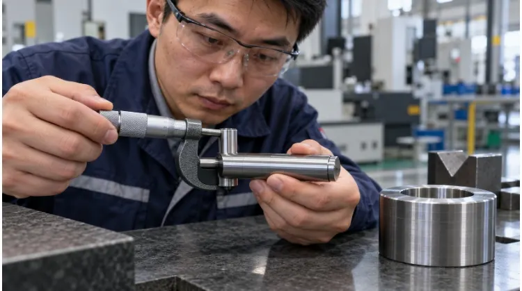
The “Rule of 10” in Metrology: Press fit tolerances often span just a few microns. Industry standard dictates the “Rule of 10″—your measuring equipment must have a resolution 10 times finer than the tolerance band. A standard caliper is virtually useless here; bore micrometers and Coordinate Measuring Machines (CMMs) are mandatory.
Post-Assembly: The interference creates internal stress that alters the geometry of the completed unit. If you press a bearing into a thin-walled housing, the housing will bulge outward. If you press a solid shaft into a hollow sleeve, the sleeve’s internal bore will shrink. Post-assembly inspection must verify critical functional dimensions, such as the final internal bore of bushings, external hub deformation, and the runout (concentricity) of rotating assemblies.
Performance Tests
To validate that the assembly will hold up in the field, manufacturers rely on specific performance tests:
- Force-Displacement Monitoring: Modern hydraulic presses can plot the force required over the insertion distance. A sudden spike in force indicates a burr or misalignment, while a drop in force indicates an undersized shaft.
- Push-Out / Pull-Out Testing: Applying axial force until the joint fails to verify its ultimate static holding capacity.
- Slip Torque Testing: Applying rotational force to confirm the joint can transmit the required torque without slipping.
Typically, destructive tests (pull-out/torque) are performed during First Article Inspection (FAI) to establish a baseline. For volume production, monitoring the pressing force serves as an efficient, non-destructive quality gate. For critical applications, prototype assemblies should also undergo thermal cycling or fatigue testing to verify long-term reliability against cyclic loads.
Press Fit Troubleshooting Guide
| Issue / Symptom | What to Check First | Engineering Assessment |
| Abnormally high pressing force | Dimensions, burrs, alignment, surface finish. | Is the interference exceeding the maximum limit, or is there physical galling? |
| Binding, tight rotation, or high runout after assembly | Hub deformation, adjacent bore sizes, fixture support. | Did the pressing stress deform the component and impact its function? |
| Joint slips or loosens under load | Actual machined dimensions, operating temp, applied loads. | Is the minimum contact pressure sufficient for the field requirements? |
| Red dust (iron oxide) or fretting wear appears | Cyclic loads, contact area conditions. | Is micro-slipping occurring due to vibration or insufficient interference? |
| Inconsistent assembly across a batch | Machining variance, surface coating thickness, press records. | Which preceding process is fluctuating? (e.g., CNC tool wear drifting, or uneven plating thickness) |
Request a Manufacturing Review for Your Press Fit Components
Tight tolerances drive up manufacturing costs. Don’t pay for an IT5 precision grind if an IT7 turned fit combined with a thermal assembly will achieve the same holding power. Before finalizing your next design, let our engineering team review your requirements to ensure optimal manufacturability.
Submit your paired component drawings, material selections, required surface treatments, applied loads, and operating temperatures to TZR. We will review the design for tolerance feasibility, recommend the most cost-effective CNC machining routing, and establish a reliable inspection plan.