
 English
 Spanish
 German
 Russian
 Italian
 French

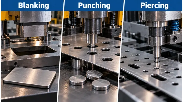
In sheet metal fabrication, the difference depends on what becomes scrap. Blanking cuts out your final part from the sheet. Punching creates a hole, keeping the sheet and discarding the removed slug. Piercing functions like punching but is typically used for smaller, precise holes.
Mixing up these terms on an RFQ or technical drawing can lead to miscommunicated tooling requirements and inaccurate quotes. While the physical mechanics—using a press to push a punch through metal into a die—are nearly identical, the terminology dictates your engineering intent.
To clarify how these processes interact on the shop floor, we will use a simple sheet metal part to explain how these operations affect dimensions, cut edges, tooling design, and unit costs.
| Process | Main purpose | What you keep | Typical scrap |
| Blanking | Cut the outer profile | The cut-out blank | Surrounding stock |
| Punching | Create holes or cut-outs | The sheet with openings | Removed slugs |
| Piercing | Create internal openings; often overlaps with punching | The sheet with openings | Removed slugs in conventional shearing |
Note: This article focuses on conventional sheet metal shearing. Operations involving material forming, such as hole flanging or extruding, require different tooling mechanics and are categorized separately in technical design.
Understand the Main Differences Between the Operations
Clear communication between engineering and manufacturing starts with using standard terminology. Here is how these three terms are applied in a production environment.
Blanking
Blanking is a shearing operation used to cut the outer profile of a part from a larger piece of sheet metal or coil. The cut-out piece is your final product (the blank), while the surrounding stock material is discarded as scrap.
Blanking is not defined by the size of the part or when it happens in the manufacturing routing. A blank can be a finished flat washer, or it can be the starting flat pattern that moves on to secondary operations like bending, deep drawing, or machining. The defining characteristic is simply that the tool isolates and retains the material on the inside of the cut line.
Punching
Punching removes material from a larger sheet to create internal features. The punch and die shear specific shapes—such as round holes, obrounds, or rectangular cut-outs—into the workpiece.
In punching, the larger sheet with the newly created openings is the part you keep. The piece of metal that gets pushed through the die is called a slug, which is typically treated as scrap. Punching is highly repeatable and serves as the standard process for creating mounting holes, ventilation slots, and connector cut-outs.
Piercing
In many sheet metal shops, “piercing” and “punching” are used interchangeably to describe cutting internal holes. However, it is important to clarify the terminology.
Historically, piercing was sometimes used to describe shearing small, precise holes, or tight clusters. In conventional stamping, piercing still generates a scrap slug. This distinguishes it from forming operations—like hole extruding or creating flanged holes—where a pointed tool displaces and stretches the metal to create a collar without removing material. When discussing flat pattern shearing, expect piercing to function exactly like punching: keeping the sheet and discarding the slug.
See the Operations on a Simple Bracket
To see how these operations interact, consider a standard L-bracket with two circular mounting holes. A single sheet metal part usually requires both an external profile and internal features.
The Finished Features
When examining the finished bracket, you see a bent piece of metal with two holes. Before bending, this part exists as a 2D flat pattern.
The outer perimeter of this flat pattern is created by blanking. The two circular mounting holes inside that perimeter are created by punching. Separating the features this way allows engineers to determine which tool dimensions will dictate the final tolerances of the part—the blanking die controls the outer dimensions, while the piercing punches control the internal hole diameters.
Operation Sequence
The sequence of these operations depends on part handling, material support, and feeding mechanisms, rather than a fixed rule of “punch first, blank later.”
A standard shop-floor routing for our bracket is to punch the internal holes first. Once punched, the tooling uses these holes (or dedicated pilot holes punched in the scrap area) to insert locating pins. These pilots lock the metal strip perfectly in position before the blanking punch shears the outer profile. If the process were reversed—blanking a small, loose part first—securing that blank to punch the holes would slow down cycle times and severely degrade positional accuracy.
Combined Dies
For low-volume production, punching and blanking are often done on separate CNC machines. For high-volume runs (typically exceeding 10,000 to 50,000 parts), these operations are integrated into press tools to lower the per-part cost, despite the higher initial tooling investment.
- Compound Dies: The internal punching and the external blanking happen at a single station during a single stroke of the press. Because the part does not move between operations, the positional tolerance between the holes and the outer edge is highly accurate, typically holding tolerances as tight as ±0.05 mm depending on material thickness.
- Progressive Dies: The metal strip is fed through multiple stations. The bracket’s holes might be punched at station one. The strip then advances to station two, where pilot pins align it before the perimeter is blanked. This setup works well for high-speed mass production and complex parts that require forming or bending steps alongside shearing.

How Tooling Affects Dimensions and Cut Edges?
Although blanking and punching share the same mechanical shearing principles, they target different areas of the metal. This distinction directly dictates how tooling is sized, how clearances are calculated, and what the final cut edge will look like in production.
Punch and Die Sizes
In shearing operations, the part you want to keep determines whether the punch or the die serves as the master dimension.
- In punching: The punch dimension dictates the final size of the hole. As the punch retracts, the hole in the workpiece springs back slightly, gripping the punch, while the scrap slug expands slightly as it drops into the die.
- In blanking: The die dimension dictates the final outer size of the blank. The cut blank will expand slightly once pushed through the die due to the release of internal stresses.
Engineers must also account for the difference between nominal CAD dimensions and actual production results. As tools wear over thousands of cycles, punch diameters decrease and die openings enlarge. Toolmakers factor in these wear allowances, along with material elastic recovery (springback), when machining the die sets.
Die Clearance
Die clearance is the intentional gap between the punch and the die block. It can be expressed as radial clearance (the gap on one side) or total clearance (the difference between the punch and die diameters).
Clearance must be engineered based on the material type, sheet thickness, and the desired edge profile. While it is not a universal fixed percentage, typical total clearance for mild steel ranges between 5% to 10% of the material thickness, whereas harder materials like stainless steel generally require 10% to 15%.
A common misconception is that tighter clearance always yields a better edge. If the clearance is too tight, the material undergoes secondary shearing, resulting in a jagged edge and accelerated tool wear. Conversely, if the clearance is too loose, the metal bends over the die edge before shearing, creating a massive rollover and heavy burrs.
Edge Quality
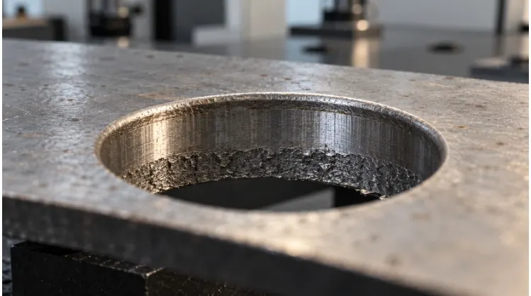
A conventional sheared edge is not a perfectly flat, vertical surface. If you examine a punched hole or a blanked perimeter, you will see four distinct zones:
- Rollover: The rounded plastic deformation at the top surface where the punch first compresses the material.
- Burnish: The smooth, vertical band where the material was cleanly sheared by the tool.
- Fracture: The rough, angled zone where the material’s tensile strength was exceeded, causing it to tear away.
- Burr: The sharp, protruding lip on the bottom edge where the fracture finally separated.
These zones impact assembly and fitment. As a general industry rule of thumb, an acceptable burr height in conventional shearing is typically up to 10% of the material thickness. If a large fracture zone or burr interferes with mating parts, acts as a stress concentrator, or poses a safety risk, secondary operations (like tumbling or wire brushing) must be specified. For applications requiring a 100% smooth burnish band (such as gear teeth), conventional shearing is insufficient, and specialized processes like fine blanking must be evaluated.
Design Holes and Profiles for Reliable Production
To transition a design from a CAD model to a reliable production run, engineers must review the flat pattern against physical machining limits. Applying standard Design for Manufacturability (DFM) rules prevents tool breakage and ensures consistent part quality.
Holes and Slots
When designing holes and slots, the critical metric is the ratio between the hole diameter (D) or slot width and the material thickness (T).
If a punch is too narrow relative to the material thickness, the compressive force required to shear the metal will exceed the compressive strength of the punch itself, causing it to buckle or snap. Furthermore, ejecting the slug out of a deep, narrow die opening becomes unreliable.
While heavy-duty punches and specialized coatings can push limits, a safe engineering baseline is:
- Aluminum: D ≥ 1.0T
- Mild Steel: D ≥ 1.2T
- Stainless Steel: D ≥ 1.5T
Shop-floor Note: Always evaluate if a custom hole size is strictly necessary for the design’s function. Specifying standard fractional or metric hole sizes (e.g., 6.0 mm instead of 6.13 mm) allows the manufacturer to use off-the-shelf tooling, significantly reducing setup costs and lead times.
Feature Spacing
Deformation is a primary risk when features are placed too close to each other or to the edge of the part. When evaluating spacing, always measure the “web” (the clear material distance between the edges of the features), not the center-to-center distance.
- Hole to Hole / Hole to Edge: The web thickness should generally be at least 2.0T. Narrower webs lack the structural integrity to withstand the shearing forces, leading to bulging edges, twisted webbing, or tearing between holes.
- Hole to Bend: If a hole is punched before the part is bent, it must sit outside the bend’s deformation zone. A standard rule is to keep the edge of the hole at least 2.5T + bend radius away from the bend line. Placing a hole inside this zone will cause the circular cut-out to stretch and distort into an oval as the metal folds.
Material Selection
Material specifications (grade, temper, and thickness) dictate the required press tonnage and determine the lifespan of the tooling.
- Aluminum (e.g., 5052-H32): Highly ductile, requires lower tonnage, and shears cleanly with tighter clearances.
- Mild Steel (e.g., 1018 CRS): Serves as the baseline for most stamping calculations. It offers a predictable balance of shear strength and tool wear.
- Stainless Steel (e.g., 304/316): Possesses high shear strength and severe work-hardening characteristics. It requires roughly 50% more shear force (tonnage) than mild steel of the same thickness, necessitates larger die clearances, and causes tooling to wear out significantly faster.
Engineers should not rely solely on material hardness to predict machining behavior; ductility is equally critical. Harder tempers will snap cleaner during blanking (producing a smaller rollover and burnish zone), but they are far more prone to edge cracking and severe springback during subsequent bending operations.
Compare Production Costs and Prepare Clear Drawings
Choosing between dedicated blanking dies, CNC punching, or alternative methods like laser cutting ultimately comes down to unit economics and how clearly you communicate your requirements to the manufacturer.
Total Part Cost
The true cost of a sheet metal part extends far beyond the press cycle time. When procurement teams evaluate a manufacturing route, they must account for the entire production lifecycle. A complete cost breakdown includes:
- Fixed Upfront Costs (NRE): Tooling design, die machining, and initial press setup.
- Variable Processing Costs: Machine time, labor, tool maintenance, and secondary operations (such as deburring, tumbling, or plating).
- Material Utilization: Given that raw material can account for 50% to 70% of a stamped part’s final cost, the scrap webbing between parts (determined by nesting efficiency on the strip or coil) is a massive cost driver.
Procurement managers must also weigh the stability of the product design. Dedicated blanking or compound dies offer excellent long-term ROI for stable, repeat orders. However, if the product is still iterating, even a minor design change—such as shifting a hole location by 2.0 mm—can render a $5,000 hard die useless, instantly destroying the expected cost savings.
Process Break-Even
When selecting a manufacturing method, engineers analyze the cost-crossover point between fixed investments and variable unit costs. The three standard options present a sliding scale of investment:
- Laser Cutting: Zero fixed tooling costs, but the highest variable cost per part due to slower cutting speeds.
- CNC Turret Punching: Minimal tooling costs (utilizing standard punch geometries), with moderate variable costs and cycle times.
- Dedicated Press Tooling (Hard Dies): High upfront fixed costs, but extremely low variable costs due to single-stroke processing. This allows the initial tooling investment to be amortized down to pennies per part over high-volume runs.
There is no universal volume threshold (e.g., “always build a die at 5,000 parts”) that dictates when to switch from laser cutting to hard tooling. The break-even point depends entirely on the part’s footprint, perimeter complexity, and material thickness. A simple, small rectangular blank might justify a dedicated die at just 2,000 units, while a large, highly complex enclosure might remain more cost-effective on a laser up to 10,000 units.
Drawing Checklist
To receive an accurate quote and ensure parts pass inspection, your technical drawings should dictate the required results rather than strictly dictating the manufacturing process. Use this checklist before submitting an RFQ:
- Files and Specifications: Provide both a 3D CAD model and a revision-controlled 2D drawing. Explicitly state the material grade, temper, and thickness (e.g., 5052-H32 Aluminum, 2.0 mm).
- Tolerances and Datums: Clearly define the primary inspection datums. Mark the critical dimensions—such as specific mounting hole diameters, positions, flatness, and overall profile limits.
- Edge Requirements (Punch vs. Die Side): Do not leave edge quality open to interpretation. Specify the maximum allowable burr height (e.g., “Max burr 0.1 mm”). Crucially, clearly indicate the primary cosmetic or mating face on your drawing. This allows the factory to dictate the punch direction, ensuring that the smooth rollover is on the visible face and any unavoidable burrs are kept on the hidden or non-interfering side of the assembly.
- Formed Features: For features like extruded or flanged holes, specify the final geometric requirements (such as inner diameter and minimum thread engagement depth) rather than telling the factory which specific punch geometry to use.
- Production Context: Include Estimated Annual Usage (EAU), typical batch release quantities, expected lead times, and required quality documentation (such as First Article Inspection – FAI reports or material certificates).
Ready to move your flat patterns into production? Submit your 2D drawings, 3D CAD files, material specifications, and batch quantities to our engineering team. We will evaluate the most cost-effective manufacturing route for your project—whether that is CNC punching, laser cutting, or dedicated blanking dies—and review your hole sizing, web spacing, and edge requirements to ensure reliable, repeatable manufacturing.