
 English
 Spanish
 German
 Russian
 Italian
 French

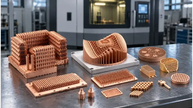
Copper 3D printing is an advanced metal additive manufacturing process used to produce complex, fully dense copper parts. Utilizing technologies like LPBF or Binder Jetting, it combines copper’s superior thermal and electrical conductivity with the geometric freedom to create conformal cooling channels and consolidated assemblies impossible via traditional machining.
However, industrial copper additive manufacturing is not a direct replacement for standard CNC machining. It is a premium, high-cost process. You should only specify printed copper—whether pure copper utilizing green lasers or alloys like CuCrZr—when your design demands thermal management limits or internal fluid dynamics that traditional tooling simply cannot deliver.
This guide is designed to help engineers and procurement teams evaluate whether copper 3D printing makes financial and technical sense for their project. It outlines how to select the right material, establish actual manufacturing limits, check your CAD design, and prepare the precise documentation required for accurate supplier quoting.
When to Choose Copper 3D Printing
Additive manufacturing is rarely the most cost-effective method for simple block geometries or standard cylindrical profiles. This section helps you quickly determine if your project warrants the cost of AM.
Internal Channels and Part Consolidation
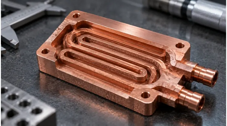
The most common justification for copper 3D printing is the integration of internal fluid channels. Traditional manufacturing requires straight, cross-drilled holes that must be plugged, which limits fluid paths and introduces potential leak points. AM allows fluid paths to follow the exact external contour of a heat exchanger or mold insert (conformal cooling).
However, this structural freedom comes with strict constraints. Unfused metal powder must be physically evacuated from internal cavities after printing. Channels under 3mm in diameter or those featuring sharp 90-degree dead-ends often trap powder permanently. If powder cannot be cleared, the part is scrap. Furthermore, the internal surface roughness of printed copper typically ranges from Ra 10 to 15 μm. This rough internal texture increases fluid pressure drop, requiring you to recalculate pump requirements and fluid dynamics during the design phase.
Performance Benefits and Manufacturing Limits
It is necessary to separate the base properties of copper from the performance gains of the printed structure. While copper provides excellent baseline thermal conductivity, the actual performance leap in AM usually comes from increasing the surface area-to-volume ratio through complex fins, lattices, or thin walls.
A complex shape is only valuable if it can survive the manufacturing process. Thin walls designed for maximum heat transfer may distort or fail during printing due to extreme thermal gradients. Every complex design must be validated for printability and thermal stress, ensuring that theoretical performance benefits do not compromise manufacturing stability.
Copper 3D Printing vs. CNC and Casting
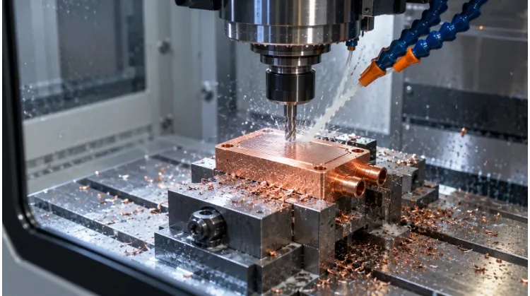
3D printing does not replace CNC machining; in reality, they are usually combined. A part is often printed near-net-shape, and critical O-ring grooves, threads, or mating surfaces are then CNC machined to meet standard tolerances.
Manufacturing Route Selection Matrix
| Decision Criteria | CNC Machining | Investment Casting | Metal 3D Printing (AM) |
| Geometry | Best for line-of-sight features, flat surfaces, and tight standard tolerances. | Works well for uniform wall thicknesses and moderate internal complexity. | Required for blind conformal channels, lattices, and organic topologies. |
| Tooling Cost | Low to moderate (custom fixtures/jigs). | High (requires molds/patterns). | None. |
| Tolerances & Finish | High precision (±0.01 mm to ±0.05 mm), excellent surface finish. | Moderate precision, requires secondary machining for critical faces. | Lower precision (±0.1 mm to ±0.2 mm), Ra 10-15 μm. Always requires CNC for mating surfaces. |
| Lead Time | Fast (days to weeks), depending on machine availability. | Slow (weeks to months) due to mold production. | Fast (days to weeks), directly from CAD data. |
Copper Materials and Their Properties
The selection of a copper material in 3D printing involves a trade-off between thermal/electrical conductivity, mechanical strength, and printability.
Pure Copper
Pure copper (>99.9% Cu) is specified when maximum electrical and thermal conductivity are non-negotiable, such as in high-frequency induction coils or heavy-duty electrical contacts.
Manufacturing pure copper via traditional laser powder bed fusion (LPBF) is notoriously difficult due to the material’s ~95% reflectivity under standard infrared lasers. While modern green and blue laser systems have solved this absorption issue, these specific machines are still relatively scarce in the global supply chain. This limited machine availability often translates to longer lead times and significantly higher quoting prices compared to copper alloys. Additionally, achieving forged-like properties in pure copper usually requires Hot Isostatic Pressing (HIP) to eliminate micro-porosity.
CuCrZr and CuNi2SiCr
Because pure copper is challenging to print and relatively soft, copper alloys act as the industry workhorses.
From a cost-to-performance and supply chain maturity perspective, CuCrZr (Copper-Chromium-Zirconium) is the default choice for over 80% of copper AM projects. It sacrifices a small percentage of conductivity but provides much higher tensile and yield strength than pure copper, making it ideal for structural thermal applications like aerospace combustion chambers.
CuNi2SiCr (Copper-Nickel-Silicon-Chromium) trades off more conductivity but achieves exceptional hardness and wear resistance after heat treatment. It is primarily specified for injection mold inserts that require localized cooling and must withstand high-pressure manufacturing environments.
Material Data and Test Conditions
When reviewing material data sheets, values for yield strength or conductivity are meaningless without context. Properties vary drastically depending on the build orientation (Z-axis versus X/Y-axis) and the applied thermal post-processing.
Procurement Tip: When reviewing supplier quotes, always request the material data sheet for the exact machine and heat treatment cycle they intend to use. Specify that the “as-built” density must be at least 99.5% to ensure structural integrity prior to any heat treatment or HIP processes.
Typical Copper AM Material Properties(Values represent typical industry ranges for LPBF processes. Missing data indicates high variability depending on proprietary processing methods.)
| Material | Electrical Conductivity (% IACS) | Thermal Conductivity (W/m·K) | Yield Strength (MPa) | Process and Condition | Source Reference |
| Pure Copper | 90 – 100% | 350 – 390 | 100 – 150 | LPBF (Green/Blue Laser) + HIP | Standard Industry Data |
| CuCrZr | 70 – 80% | 300 – 320 | 350 – 450 | LPBF + Solution Annealed & Aged | Common Supplier Specs |
| CuNi2SiCr | 35 – 45% | 160 – 200 | 600 – 750 | LPBF + Solution Annealed & Aged | Common Supplier Specs |
Copper 3D Printing Processes Compared
Not all metal 3D printing technologies handle copper the same way. The choice of process strictly dictates your volume limits, geometric freedoms, and the final density of the part.
Laser Powder Bed Fusion (LPBF)
(Commercially referred to as DMLS or SLM)
- The Process: A laser selectively melts metal powder layer by layer in an inert gas environment (usually Argon or Nitrogen). Pure copper requires specialized green or blue lasers for efficient absorption, while standard infrared lasers handle copper alloys (CuCrZr, CuNi2SiCr) effectively.
- Applicable Parts: Complex heat exchangers, high-frequency induction coils, and conformal cooling inserts requiring fine feature details and high density (>99.5%).
- Main Limits: Rapid heating and cooling cycles generate severe residual thermal stress. Parts must be heavily supported to prevent warping, which limits design freedom on downward-facing surfaces.
- Post-Processing & Validation: Parts require thermal stress relief while still welded to the build plate before they can be cut off (typically via wire EDM).
Electron Beam Powder Bed Fusion (E-PBF)
- The Process: Uses an electron beam in a high-vacuum chamber at elevated temperatures. Before the commercialization of green/blue lasers, E-PBF was the only reliable way to print highly dense pure copper because electron beams do not suffer from optical reflectivity issues.
- Applicable Parts: Oxygen-sensitive copper components that require extremely low residual stress, allowing for bulkier geometries without the risk of thermal cracking.
- Main Limits: The high ambient heat of the chamber lightly sinters the entire powder bed into a semi-solid “cake.” Removing this caked copper from complex internal channels is brutally difficult. E-PBF also produces a significantly rougher surface finish (Ra 20-35 μm) than LPBF.
- Post-Processing & Validation: Requires aggressive powder recovery blasting. While stress relief is usually unnecessary, CNC machining allowances must be larger to compensate for the rough as-built surface.
Binder Jetting
- The Process: A printhead jets a liquid binding agent onto the copper powder bed to form a fragile “green part.” The part is then debound and sintered in a furnace to reach near-full density.
- Applicable Parts: Medium-to-high volume production runs (hundreds to thousands of units) where LPBF becomes cost-prohibitive, such as small thermal spreaders or electrical contacts.
- Main Limits: Parts shrink by 15% to 20% during final sintering. Furthermore, copper oxidizes violently at high temperatures. Sintering cannot be done in a standard vacuum; it requires a highly controlled reducing atmosphere (such as a hydrogen-argon forming gas) to prevent severe oxidation and ensure metallurgical bonding.
- Post-Processing & Validation: Tight tolerances require rigorous upfront validation. You must budget for several trial runs to dial in the non-linear shrinkage compensation in your CAD model before volume production.
Bound Metal Extrusion (BME)
- The Process: Operates similarly to desktop FDM, but the filament/rod consists of functional copper powder suspended in a polymer matrix. After printing, the part undergoes debinding and furnace sintering. (Note: This produces solid metal, not to be confused with decorative copper-infused PLA).
- Applicable Parts: Low-cost functional prototyping, jigs, or tooling where maximum density and high precision are not critical.
- Main Limits: Cannot produce the fine internal channels or lattice structures of LPBF. Final porosity is generally higher (~95-98% dense), which measurably reduces thermal and electrical conductivity.
Copper AM Process Comparison Matrix(Note: Directed Energy Deposition (DED) and Cold Spray are also utilized for copper, but primarily for repairing large forgings or coating dissimilar metals, not for generating complex primary geometries).
| Process | Volume Sweet Spot | Min Wall Thickness | As-Built Roughness (Ra) | Key Engineering Trade-off |
| LPBF | 1 – 50 | 0.4 mm | 10 – 15 μm | Highest detail, but requires heavy support structures and stress relief. |
| E-PBF | 1 – 20 | 1.0 mm | 20 – 35 μm | Low residual stress, but sintered powder is exceptionally hard to clear from cavities. |
| Binder Jetting | 500 – 10,000+ | 1.5 mm | 5 – 10 μm | High throughput, but managing 20% shrinkage and reducing atmospheres is difficult. |
| BME | 1 – 10 | 2.0 mm | 15 – 25 μm | Low machine cost, but lacks density and fine feature capability. |
Design Guidelines for Copper Parts
Designing for copper 3D printing requires accepting that the CAD model you send to the printer is not the final part. Every feature must be designed with powder removal, thermal dynamics, and secondary machining in mind.
Wall Thickness, Holes and Small Features
There is a strict difference between a machine’s “minimum printable size” and a “stable production size.”
- Wall Thickness: While LPBF can technically fuse walls down to 0.2 mm, designing copper walls below 0.8 mm risks thermal distortion or structural failure during pressurized powder removal.
- Holes: Do not 3D print standard circular holes smaller than 1.5 mm in diameter. It is cheaper, faster, and more accurate to print the area solid and CNC drill the holes afterward.
Internal Channels and Powder Removal
If your design leverages conformal cooling, the cross-section of the channel dictates the success of the build.
- Self-Supporting Geometries: Circular horizontal channels will collapse at the top due to a lack of support. Use teardrop or diamond-shaped profiles for any internal channel exceeding 6 mm in diameter.
- Powder Evacuation: Ensure every internal channel has at least two exit ports. Powder cannot be flushed from a dead end.
- Inspection Access: If fluid flow is critical, design the channel exits so that a standard industrial borescope can be inserted for internal visual inspection.
Build Orientation and Support Access
In LPBF, the orientation of the part dictates where support structures are placed (typically on overhangs below 45 degrees). However, copper introduces a unique challenge: The Heat Sink Effect.
Because copper is highly thermally conductive, supports do not just hold the part up—they rapidly draw heat away from the melt pool. Poorly designed supports will cause localized cooling gradients, leading to melt pool instability, porosity, or severe warping.
Additionally, printed copper supports are highly ductile and tough. Unlike aluminum supports which can sometimes be snapped off, copper supports must be aggressively milled or ground away. Never design critical sealing surfaces on downward-facing orientations, as the support removal will destroy the tolerance.
Tolerances and Machining Allowances
Print exactly what you need for rough geometry, and leave extra material for what must be precise.
- As-printed tolerances: Expect ±0.1 mm to ±0.2 mm depending on the feature size and orientation.
- Machining Allowance (Stock): For bearing fits, O-ring grooves, threaded holes, and mating flanges, add 1.0 mm to 1.5 mm of extra stock material in your CAD model. You will CNC mill these faces to final dimensions after heat treatment.
Post-Processing and Inspection
A printed copper part is essentially a raw, high-tech casting. Moving it from the build plate to a field-ready state often accounts for 40% to 60% of the total unit cost.
Cleaning and Support Removal
Extracting unfused powder from copper parts is critical because trapped copper powder adds significant unwanted mass and blocks thermal transfer. Technicians use ultrasonic vibration and compressed air. Support removal is typically done with wire EDM to slice the part off the build plate, followed by 3-axis or 5-axis CNC milling to remove the remaining lattice.
Heat Treatment and Material Condition
Thermal post-processing dictates the final mechanical behavior of the part.
- Stress Relief: Mandatory for all LPBF parts before removal from the plate to prevent distortion.
- Solution Annealing & Aging: Applied to alloys like CuCrZr and CuNi2SiCr to precipitate alloying elements, drastically increasing yield strength and hardness.
- Hot Isostatic Pressing (HIP): Places the part under extreme heat and argon gas pressure to collapse internal micro-voids, pushing density from 99.5% to virtually 100%. HIP is expensive and usually only specified for parts subject to high-pressure fluids or severe fatigue loading.
Machining and Surface Requirements
3D printing cannot tap a reliable thread or create a vacuum-tight seal.
- Mating Surfaces: Must be CNC milled or ground to achieve flatness and a surface finish of Ra 1.6 μm or better.
- Internal Channels (The AFM Trap): If the as-built internal roughness (Ra 10-15 μm) causes unacceptable fluid turbulence, Abrasive Flow Machining (AFM)—pumping a pressurized abrasive putty through the channels—can be used. However, AFM is a subtractive process. If you plan to use AFM, you must compensate in your initial CAD design by thickening the channel walls. Failing to do so will result in oversized channels and compromised wall strength.
Inspection by Part Function
Do not over-specify inspection requirements; it unnecessarily drives up costs and extends lead times.
The CT Scan Warning: Many engineers default to requesting “100% CT Scan” for internal void detection. Due to copper’s extreme density (radiopacity), standard industrial X-ray equipment cannot penetrate thick copper sections. Inspecting dense copper requires specialized, highly expensive MeV-level X-ray sources. Specify CT scanning only when internal failure carries catastrophic consequences.
Targeted Inspection Requirements
| Component Function | Critical Requirement | Recommended Inspection Method | Deliverable Record |
| High-Pressure Heat Exchanger | No internal leaks or micro-cracks | Helium leak testing; High-Energy CT Scan | Leak rate certificate; CT report |
| Induction Coil | Maximum electrical transfer | Eddy current testing (conductivity mapping) | % IACS Material Certificate |
| Mold Insert (CuNi2SiCr) | Wear resistance and sealing | Hardness testing (Rockwell/Vickers); CMM check | Hardness report; CMM dimension log |
| Thermal Spreader | Clear internal pathways | Flow rate testing; Borescope visual inspection | Flow capability (L/min) at specific pressure |
Copper 3D Printing Applications
The following examples demonstrate how the material selection and design guidelines discussed earlier are applied to physical manufacturing limits. These represent standard industrial use cases where the high cost of additive manufacturing is justified by measurable performance data.
Heat Exchangers and Cooling Plates
- The Original Problem: High-power electronics (such as EV traction inverters or radar systems) require active liquid cooling. Traditional cold plates rely on cross-drilled aluminum blocks or brazed copper plates. Cross-drilling limits the fluid path to straight lines, creating thermal dead zones. Brazed plates often fail at the joints under heavy thermal cycling due to fatigue.
- Design Choice: A monolithic pure copper cold plate featuring internal gyroid lattice structures. The gyroid maximizes the internal surface area for heat transfer while simultaneously acting as its own internal support structure during the LPBF print.
- Manufacturing Requirements: Printed using a green laser LPBF system to ensure >99.5% density. The lattice wall thickness was strictly held at 0.6 mm to withstand the pressures of ultrasonic powder removal.
- Validation Results: In a standardized test environment (coolant inlet at 20°C, flow rate of 5 L/min), the monolithic printed plate eliminated all brazed joint leak risks and reduced thermal resistance by 35% compared to the traditional cross-drilled aluminum counterpart.
Induction Coils
- The Original Problem: Traditional induction heating coils for gear hardening are manually bent from copper tubing. For complex gear profiles, manual bending creates inconsistent stand-off distances between the coil and the workpiece, leading to uneven heat distribution and localized metallurgical weaknesses in the gear.
- Design Choice: A custom-profiled pure copper coil printed to conform exactly to the gear’s geometry. The internal cooling channel was designed with variable wall thicknesses—thinner near the heating face to maximize cooling, and thicker at the rear for structural rigidity.
- Manufacturing Requirements (The Skin Effect Trap): High-frequency AC currents suffer from the Skin Effect, meaning the electrical current only travels along the extreme outer layer of the conductor. The as-built rough surface (Ra 15 μm) of a 3D-printed coil acts as a severe resistor, generating immense unwanted self-heating. Therefore, after printing and Hot Isostatic Pressing (HIP), the coil’s exterior had to be chemically and mechanically polished to a smooth finish. This secondary polishing is mandatory to actually realize the 95% IACS conductivity.
- Validation Results: When installed on the production line, the conformal coil eliminated the cold spots caused by hand-bent coils and reduced the overall gear hardening cycle time.
Copper Alloy Cooling Inserts
- The Original Problem: In plastic injection molding, deep core geometries often trap heat. Standard straight-line water cooling cannot reach the tip of the core, causing the molded plastic part to warp during ejection and forcing the factory to run longer cooling cycles.
- Design Choice: A CuNi2SiCr mold insert featuring conformal cooling channels that loop exactly 2.5 mm beneath the external molding surface.
- Manufacturing Requirements: Printed via standard infrared LPBF. The insert was printed oversized by 1.5 mm on all critical surfaces. After printing, it underwent solution annealing and aging to reach ~40 HRC, followed by 5-axis CNC milling to achieve the final mold tolerances and a sealing surface finish of Ra 0.4 μm.
- Validation Results: Installed in a high-volume automotive injection mold, the CuNi2SiCr insert reduced the overall cooling cycle time from 45 seconds to 32 seconds, directly increasing the hourly output of the molding press.
Ready to Validate Your Copper Design?
If you are developing conformal cooling inserts, high-frequency coils, or complex heat exchangers, the manufacturing strategy must be integrated into the CAD model from day one.
At TZR, we specialize in the critical intersection of advanced metal additive manufacturing and precision CNC machining. We don’t just print raw shapes; we engineer them for actual production.
Send us your STEP files to get started. Our engineering team will review your internal channels for powder evacuation, identify critical CNC machining allowances, design the necessary fixturing datums, and provide a comprehensive manufacturing quote that covers everything from the initial laser melt to the final CMM inspection.