
 English
  Spanish
  German
  Russian
  Italian
  French
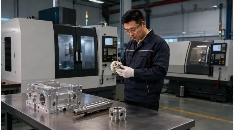
The main difference between CNC milling and CNC turning is the movement of the workpiece and the tool. In milling, a rotating cutting tool shapes a stationary part, ideal for flat and complex surfaces. In turning, the part rotates against a stationary tool, perfect for cylindrical components.
However, choosing the most economical manufacturing route for a specific project goes far beyond identifying whether a part is square or round. While basic geometry provides the starting point, the final decision is often dictated by setup count, datum relationships, required surface finishes, and total production volume.
To bridge the gap between a CAD model and a final quote, the following breakdown focuses entirely on practical DFM constraints and the factors that actually drive up manufacturing costs.
Use the quick decision matrix below to evaluate the best starting process for your next component:
| Part characteristics | Initial process choice | Factors to confirm | Cost / Lead Time Impact |
| Flat faces, pockets and multi-side features | CNC milling | Tool access, part rotation and setup count | Multiple manual setups drive up labor cost and scrap risk. |
| ODs, IDs, tapers and axial threads | CNC turning | Workholding, length-to-diameter ratio and runout | Highly cost-effective for concentric features. |
| Round body with side holes or flats | Turn then mill or mill-turn | Feature alignment, quantity and setup cost | Secondary fixtures increase lead time and tooling budget. |
| Tight relationship between turned and milled features | Evaluate mill-turn | Machine capability, inspection and hourly cost | Higher hourly rate offset by zero datum transfer time. |
| Simple mixed features in a small batch | Separate turning and milling | Fixture repeatability and datum transfer | Lower programming cost, but higher manual handling time. |
| High material removal from expensive stock | Compare alternative stock forms | Standard sizes, near-net stock and scrap value | Poor material yield on alloys like Titanium spikes unit price. |
Cutting Motion and Feature Capability
To evaluate which process fits a specific part, it is helpful to understand how each machine removes material and from which directions the cutting tool can access the workpiece.
CNC Milling
In milling, the machine spindle rotates the cutting tool. The workpiece is secured to a table, held in a vise, or mounted on a rotary axis. Because the tool moves across a stationary part, milling efficiently cuts flat planes, steps, pockets, slots, external contours, multi-directional holes, and tapped threads.
The primary constraint in milling is tool access. A standard 3-axis mill operates from one fixed direction. If the part requires machining on multiple sides, the operator must manually flip and re-clamp the workpiece. 4-axis and 5-axis machines solve this by rotating the part to expose different faces to the spindle. As a rule of thumb, for a part with features on four sides, moving from a 3-axis to a 5-axis machine can reduce setup time from 2 hours to 20 minutes, directly lowering labor cost and minimizing human error during re-chucking.
CNC Turning
In turning, the workpiece is clamped in a chuck and rotated by the main spindle. A single-point cutting tool feeds axially or radially against the spinning material.
Turning centers naturally produce outside diameters (ODs), inside bores (IDs), end faces, steps, tapers, grooves, axial threads, and part-off features. Because the part spins around a fixed center, machining the OD, the ID, and a facing step in a single chucking inherently holds strict concentricity and runout tolerances without any extra alignment effort.
Mill-Turn Machining
Mill-turn centers integrate milling capabilities into a lathe platform. They utilize live tooling (motorized end mills and drills), a C-axis to index and lock the spindle at precise angles, and often a sub-spindle to grip the reverse end of the part.
This architecture allows a single machine to turn a cylindrical diameter, lock the spindle, and then mill a flat face, drill a cross-hole, or cut a keyway. However, utilizing a mill-turn does not guarantee a part is strictly “done-in-one.” A component may still require a secondary setup, cylindrical grinding for tight bearing fits, EDM for sharp internal corners, complex manual deburring, or hard-turning after heat treatment.
Part Geometry and Process Selection
Assigning a part to a milling or turning center requires looking beyond its basic outline. Process selection depends on how different geometric features interact, the direction they face, and how the machine will hold the raw material.
Prismatic Parts
Prismatic parts include components like equipment housings, mounting blocks, mold cavities, heatsinks, brackets, and valve manifolds.
These components are typically routed to CNC mills. Their geometry requires machining away material to form intersecting flat surfaces, pockets of varying depths, and hole patterns on multiple planes.
When reviewing prismatic parts, tool reach and part orientation are the limiting factors. Even a visually simple bracket machined from a 6061-T6 aluminum block may require three separate setups if it features tapped holes on the top, front, and side. Furthermore, deep pockets or complex surface contours dictate whether standard 3-axis machining is sufficient, or if 5-axis tool paths are required to maintain tool rigidity and reach.
Rotational Parts
Rotational parts encompass shafts, pins, bushings, custom flanges, sleeves, rollers, and custom threaded fittings.
When the primary features—such as bearing surfaces, internal bores, and sealing faces—share a central axis, the part belongs on a lathe. The engineering review here focuses on length-to-diameter (L/D) ratios to prevent material deflection, and verifies which surfaces can be safely gripped by the chuck jaws.
However, a circular profile does not automatically dictate turning. For instance, a thin, circular 316L stainless steel plate featuring extensive asymmetric pocketing and dense hole patterns might be more stable on a vertical mill. On a lathe, thin-walled circular parts often deform under chuck jaw pressure, making milling the safer geometric choice.
Mixed-Feature Parts
Many functional components require both rotational and prismatic features. Consider a custom aluminum fluid connector. This part features:
- A cylindrical main body
- An axial internal bore
- External threads
- Two radial side-holes
- Two wrench flats
- A locating face
For this geometry, three primary production routes are feasible:
- Separate Turning and Milling: The cylindrical body, bore, and external threads are machined on a standard 2-axis lathe. The part is then removed, clamped in a vise on a 3-axis mill, and the radial holes, flats, and locating face are machined.
- Turning with Live Tooling: The part is loaded into a lathe equipped with live tooling. The turning tools finish the OD and bore. The spindle then locks, and live end mills and drills cut the flats, locating face, and radial holes.
- Full Mill-Turn Center: The main spindle turns the primary OD and mills the radial features. The sub-spindle then grabs the part, a cut-off tool separates it from the bar stock, and the sub-spindle pulls the part back to machine the internal bore on the reverse end.
Geometrically, all three routes can successfully produce this connector. The final decision relies on fixture repeatability, datum transfer errors, and total setup costs—factors we will break down next.
Milling and Turning DFM Rules
Design decisions directly dictate tool selection, machining stability, material removal rates, and ultimately, cycle time. Designing for manufacturability (DFM) means understanding how a cutting tool physically interacts with the workpiece inside the machine.
Milling Feature Design
When our engineers review a part for CNC milling, we look for features that force the machine to slow down, require custom tooling, or induce vibration.
Internal Corner Radii
- Why it is difficult: Round end mills cannot cut perfectly square internal corners.
- Quality impact: Forcing a tool into a sharp corner causes chatter, gouging, and poor surface finish due to a sudden spike in tool engagement.
- Cost impact: Achieving a very tight corner requires stepping down to progressively smaller end mills, forcing multiple passes at reduced feed rates and driving up cycle time.
- Design adjustment: Design internal corner radii slightly larger than standard tool radii. For example, if a pocket depth allows for a 6mm diameter end mill, specify a 3.5mm internal radius rather than exactly 3mm. This allows the tool to sweep through the corner continuously.
Deep Pockets
- Why it is difficult: Machining deep cavities requires a long tool overhang from the spindle holder.
- Quality impact: Extended tools deflect under cutting forces, resulting in tapered pocket walls and severe chatter marks.
- Cost impact: To prevent tool breakage, the operator must drastically reduce the feed rate and depth of cut.
- Design adjustment: Limit pocket depth to 3x–4x the tool diameter, or design the pocket with stepped walls and draft angles to allow shorter, more rigid tools to do the bulk of the work.
Narrow Slots
- Why it is difficult: Narrow slots restrict the maximum diameter of the cutter, forcing the use of fragile tools.
- Quality impact: Chip evacuation becomes severely restricted. The cutter ends up re-cutting its own chips, which scores the slot walls.
- Cost impact: High tool wear and frequent tool breakage lead to machine downtime and higher tooling budgets.
- Design adjustment: Widen slots wherever possible, or design them to pass completely through the part to allow chips to cleanly flush out the bottom.
Thin Walls
- Why it is difficult: Thin cross-sections lack the rigidity to withstand the radial pressure of the cutting tool.
- Quality impact: The wall flexes away from the tool during cutting, causing dimensional inaccuracy, warping, and inconsistent thickness.
- Cost impact: Requires specialized low-force toolpaths, multiple spring passes, or stress-relieving thermal operations.
- Design adjustment: Thicken walls where space permits (e.g., maintaining at least a 1.5mm wall thickness for standard aluminum milling), or incorporate supporting ribs into the design to increase structural rigidity.
Flat-Bottom Pockets
- Why it is difficult: A perfectly sharp 90-degree transition between a pocket floor and a side wall stresses the sharp tip of a standard square end mill.
- Quality impact: Creates stress concentrations in the finished part and increases the risk of tool tip chipping.
- Cost impact: Often requires roughing with one tool and finishing with a specialized square end mill just to clean up the floor corner.
- Design adjustment: Add a small floor fillet (bull-nose radius) to the bottom edges. This allows the use of a bull-nose end mill, which is significantly stronger and can feed much faster.
Turning Feature Design
For turned components, DFM focuses heavily on how securely the part can be gripped and how the material behaves while spinning at high RPMs.
- Length-to-Diameter (L/D) Ratio: Long, slender parts tend to whip or deflect away from the cutting tool. High L/D ratios usually require a tailstock for center support or a steady rest.
- Clamping Length and Surfaces: The chuck jaws need sufficient surface area to grip the stock safely. If a part has complex contours right up to the end, extra stock must be added simply to hold the part, which is later parted off and scrapped.
- Deep Bores and Chip Evacuation: Boring bars are highly susceptible to vibration. Deep, blind bores are particularly difficult because chips build up at the bottom, risking tool crashes and scored IDs.
- Thin-Walled Cylinders: Chuck jaws exert immense radial pressure. Gripping thin tubing or boring out a thin-walled housing can crush or distort the part, meaning it will spring out of round once removed from the machine.
- Relief Grooves (Undercuts): Threading tools and boring bars need a place to start and stop cleanly. Designing thread reliefs and internal undercuts prevents the tool from crashing into a shoulder.
- Thread Runout: Tools cannot cut full-depth threads perfectly up to a perpendicular wall. Allow adequate distance for the threading tool to pull out.
- Part-Off Location: Consider where the part-off blade will separate the component from the bar stock. This operation leaves a small pip or burr that often requires a secondary facing operation if a perfectly smooth end is required.
- Tool Clearance: Internal features like stepped bores must provide enough clearance for the boring bar shank to enter without colliding with the front of the part.
Swiss-Type Machining: Swiss-type turning can be considered for small-diameter, slender parts produced from bar stock. The guide bushing supports the material close to the cutting zone, which significantly reduces deflection during machining.
Material and Stock Form
The raw form of the material—whether it is bar stock, rectangular block, plate, thin-wall tube, or a near-net forging—dictates the machining route just as much as the CAD model.
Comparing alternative stock forms is critical. Starting with standard raw material sizes minimizes heavy roughing passes. However, material utilization efficiency depends entirely on how well the final geometry matches the raw stock form, rather than a blanket rule that “turning saves more material than milling.” Generating high volumes of scrap from expensive stock heavily penalizes the unit cost.
Different materials also exhibit specific behaviors under the cutting tool, which our facility must account for during process planning:
- Stainless Steel (e.g., 316L): Prone to work hardening. Machining requires aggressive, confident feeds; rubbing the tool against the material hardens the surface, destroying subsequent cutting tools.
- Titanium (e.g., Grade 5): A poor conductor of heat. The cutting heat transfers directly into the cutting edge rather than leaving with the chip, accelerating tool wear and requiring rigid setups and tailored coolant strategies.
- Aluminum (e.g., 6061-T6): Offers excellent machinability, but the chips are abrasive and easily scratch the finished surfaces during evacuation.
- Plastics (e.g., Delrin, PEEK): Highly susceptible to heat deformation and clamping distortion. Heavy roughing passes can induce internal stresses that cause the plastic to warp days after machining.
- Thin-Wall Tubing: Often requires custom soft jaws or expanding internal mandrels to prevent jaw crushing and maintain concentricity.
Setups, Datums, and Machining Quality
Parts that look nearly identical on a CAD screen can yield vastly different manufacturing quotes. The primary driver of this discrepancy is setup count and tolerance management.
Workholding and Datum Transfer
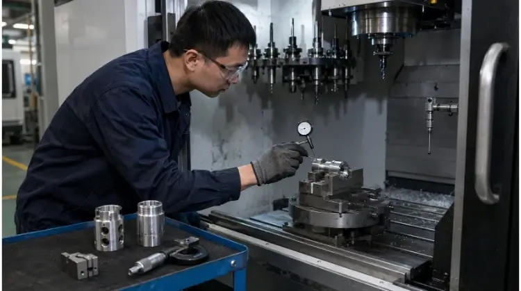
Every time a workpiece is unclamped, flipped, and re-clamped, the manufacturing process accumulates hidden costs and risks. Re-fixturing adds manual labor, dial-indicating time, the cost of custom soft jaws, work-in-progress (WIP) handling, and interim inspection steps.
More critically, re-clamping introduces datum transfer errors. Returning to our custom aluminum fluid connector example: if a shop chooses to turn the cylindrical body first and then move the part to a mill to cut the radial side-holes and wrench flats, the operator must re-locate the center axis of the cylinder in the mill vise. If those radial holes share a strict positional tolerance (e.g., a True Position of 0.05mm relative to the central bore), this secondary setup becomes the primary source of tolerance stacking and scrap risk.
However, consolidating everything into a single setup is not automatically the most economical path. If the production quantity is low, the milled features are simple, and the positional tolerances between the turned and milled features are loose, separating the operations across a standard lathe and a 3-axis mill avoids the high hourly rate and complex programming overhead of a mill-turn center.
Critical Tolerances and Inspection
A print’s functional callouts dictate the processing sequence, the datum selection, and the type of inspection required.
- Concentricity and Runout: If a shaft requires tight runout between an OD bearing journal and an ID bore, the machinist will sequence the operations to cut both features in the same chucking, eliminating re-fixturing variables.
- Perpendicularity: If an end face must be perfectly perpendicular to the central axis, facing it and turning the OD simultaneously is the safest route.
- Position and Angularity: Tight angular relationships between radial side-holes and the main body often push a part toward a mill-turn machine, where the C-axis encoder ensures exact angular placement.
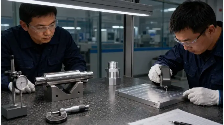
These requirements directly change quotation pricing because they dictate inspection equipment and time. General tolerances might only require calipers and micrometers. Bearing fits demand bore gauges. Tight runout requires setting the part on V-blocks with a dial indicator. True position callouts across multiple planes often mandate a Coordinate Measuring Machine (CMM) routine, requiring dedicated programming time and comprehensive First Article Inspection (FAI) reports.
Expert Tip: This is why explicitly clarifying which tolerances are strictly functional versus general standard tolerances (e.g., ISO 2768-m) on your RFQ drawing is critical. Over-tolerancing non-critical features forces the manufacturer to use slower finishing passes and CMM inspections, resulting in an artificially inflated quote.
Surface Finish and Lay
Surface roughness (Ra value) and surface texture direction (lay) are related but distinct characteristics. Simply matching the requested Ra number does not guarantee the part will function correctly if the tool marks run the wrong way.
Turning generally leaves a continuous, microscopic spiral groove—much like a vinyl record—because it is a single-point continuous cut. Milling leaves sweeping parallel, arched, or cross-hatched tool marks depending on the tool path and step-over.
The direction of these tool marks impacts friction, lubrication retention, appearance, and sealing.
Expert Tip: Consider an O-ring sealing groove. For a dynamic seal under high pressure, a spiral lay generated by standard turning can act like a microscopic thread, continuously pumping fluid past the seal as the shaft moves. In this scenario, plunge turning, roller burnishing, or subsequent grinding may be required to eliminate the spiral lay, even if the measured Ra value is already within the specified limits.
Additionally, specifying unnecessarily low surface roughness values (e.g., 0.4 µm / 16 µin everywhere) forces the machinist to reduce feed rates dramatically, swap out inserts frequently, or add secondary polishing steps. This drives up production costs significantly with no added functional value.
Production Route and Total Cost
Ultimately, engineering feasibility must translate into a procurement decision. The choice between separating operations or utilizing a multi-axis machine comes down to how setup times, labor, and machine hourly rates scale against your production volume.
Separate Milling and Turning
A traditional “turn first, mill second” routing is not inherently outdated. It is often the most economical choice for:
- Prototypes and low-volume batches: Where complex programming cannot be amortized.
- Minimal milled features: E.g., a simple shaft with a single wrench flat at one end.
- Loose feature alignment: When there is no strict GD&T relationship (like True Position or Concentricity) between the turned diameters and the milled pockets.
- Standard workholding: When standard vises and chucks can hold the part reliably without custom fixtures.
- Flexible scheduling: Splitting operations allows a shop to optimize capacity across multiple standard machines rather than bottlenecking a single, high-cost mill-turn center.
However, buyers must account for the hidden costs of split operations. The true cost is not just the cycle time of the two machines; it includes:
- Queue times: Waiting for schedule availability on two separate machines can add days to your overall lead time compared to a single-setup process.
- Manual transfer and handling between workstations.
- Repeated dial-indicating and edge-finding for the second setup.
- The cost of designing and machining custom soft jaws.
- Interim inspections between operations.
- Work-in-progress (WIP) waiting on the shop floor.
- Higher scrap risks: If the milling operator misaligns the part on the second setup, the time and material invested during the turning phase are completely lost.
Live Tooling and Mill-Turn
Mill-turn centers and lathes equipped with live tooling are designed to consolidate operations. This route is highly advantageous for:
- Cylindrical bodies with dense side features: Parts that require heavy OD turning alongside radial drilling, tapping, and flat milling.
- Strict datum alignment: When milled features must perfectly align with turned features, eliminating the re-fixturing step is the only reliable way to hold tight tolerances.
- Automated volume production: Combining mill-turn capabilities with a bar feeder allows for “lights-out” machining, drastically reducing per-part labor costs.
The trade-off is the upfront investment. Mill-turn production introduces:
- A significantly higher machine hourly rate.
- More complex CAM programming and collision simulation.
- Expensive dedicated live-tool holders.
- Longer initial machine setup and dialing-in times.
- Physical space constraints inside the machine envelope for long tools.
The Aluminum Connector Example:
Revisiting our custom aluminum fluid connector, the production volume dictates the route.
For a prototype run of 5 pieces, paying for 3 hours of complex mill-turn CAM programming makes no financial sense. Our engineers would route this to a standard lathe, then manually move it to a 3-axis mill to cut the radial holes.
However, for a production run of 2,000 pieces, the high hourly rate of the mill-turn is quickly diluted. The machine can pull raw material from a bar feeder, turn the OD, mill the flats, drill the radial holes, part it off, and drop a finished, fully-aligned connector into a parts catcher every 3 minutes—with zero manual handling and zero datum transfer errors.
Conclusion
CNC milling is generally the better starting point for prismatic parts, pockets, and multi-side features. CNC turning is usually more efficient for diameters, bores, tapers, and threads arranged around one axis. Mill-turn becomes valuable when rotational and off-axis features require close alignment or when production volume justifies reducing setups.
Ready to manufacture? Send your 3D model, technical drawing, material, quantity, and critical tolerances to us for a DFM review. Our engineers will compare milling, turning, and mill-turn routes to deliver a quote optimized for quality, lead time, and total manufacturing cost.