Sheet Metal Prototyping: DFM, Cost & Production Guide
Kevin Lee
Published:
Sheet metal prototyping is the rapid fabrication of physical metal parts from 3D CAD models using precise cutting, bending, and assembling processes. It allows engineers to validate form, fit, and functional performance before investing in expensive mass production tooling.
Yet, a sheet metal prototype can look flawless on a CAD screen and still fail disastrously on the assembly line. Incorrect bend allowances, distorted mounting holes, missing hardware clearance, and unrealistic tolerances often appear only after the first physical part is formed.
Whether you are designing a simple bracket or managing a complex assembly, this guide covers the practical steps to get it right the first time. We will walk through the DFM rules that prevent warped parts, the hidden setup fees that inflate your quotes, and the exact process for scaling up.
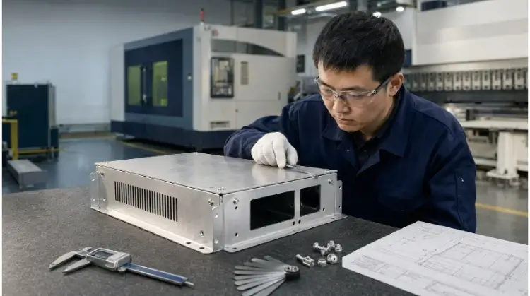
Aluminum Enclosure Prototype Under Review
What the Sheet Metal Prototype Must Prove
A prototype must answer specific engineering questions. You must define the test objective first, which then dictates the material, manufacturing method, and inspection depth.
Form, Fit, and Function
Testing generally falls into three distinct categories. A single prototype may not effectively cover all of them if the requirements conflict.
Form: Evaluates the physical shape, bend angles, and panel gaps.
Fit: Verifies hole alignments, fastener clearances, and assembly interactions with mating components.
Function: Tests material strength, stiffness, thermal dissipation, electrical grounding, and performance under load.
An appearance model cannot replace a functional prototype. While a 3D-printed plastic model works well for checking spatial volume inside a server rack, it cannot accurately replicate metal springback, structural stiffness, or electrical conductivity.
Prototype Stages and Test Depth
Different stages of product development require different levels of manufacturing precision.
Stage
Primary Validation
Manufacturing Requirement
Concept prototype
Form and spatial volume
Accepts simplified materials and finishes
Engineering prototype
Assembly and functional tests
Should closely match production-intent materials and processes
Pre-production prototype
Manufacturing controls and quality
Requires production materials and final inspection standards
A common mistake in early development is applying unnecessarily tight tolerances to a concept prototype, which drives up cost and lead time. Conversely, approving a final production run based on a simplified concept model often leads to assembly failures when the actual manufacturing process introduces variables like tool wear and welding distortion.
Sheet Metal vs. CNC and 3D Printing
Selecting the right prototyping method depends heavily on the final part structure and the test requirements.
Structural Geometry: Sheet metal is designed for uniform wall thickness and bent features. If the design requires varying wall thicknesses, deep pockets, or 3D contoured surfaces, CNC machining is required.
Material Properties: Sheet metal prototyping uses actual production alloys. 3D printing, even with metal binders, often yields different mechanical properties than cold-rolled or aluminum sheet stock.
Tolerances and Stacking: CNC machining routinely holds ±0.05 mm. Sheet metal tolerances are influenced by material thickness and bending equipment, typically ranging from ±0.1 mm to ±0.3 mm for formed dimensions. Be aware of tolerance stacking: A single bend might hold ±0.2 mm, but across a U-shaped enclosure with four bends, the tolerance stacking can reach ±0.8 mm, causing the cover panel to completely miss its mounting holes.
Scalability: A sheet metal prototype fabricated via laser cutting and CNC press braking provides a direct path to low-volume production.
Hybrid prototypes are often the most practical solution for complex assemblies. For our power supply enclosure, the main chassis is fabricated from sheet metal, an internal heat sink is CNC machined, and complex wire-routing clips are 3D printed.
Material Choices and DFM Rules That Prevent Rework
Reliable sheet metal fabrication starts with Design for Manufacturability (DFM). Material selection, bend features, hardware specifications, and drawing tolerances must be clearly defined before requesting a quote.
Materials and Stock Thickness
Using standard stock thicknesses keeps costs down and avoids Minimum Order Quantity (MOQ) delays from material suppliers.
Material
Common Applications
Key Considerations
Aluminum 5052-H32
Enclosures, panels, and brackets
Good formability; handles multiple bends well.
Aluminum 6061-T6
High-strength structures and machined parts
High risk of cracking during bending; requires appropriate bend radii.
Stainless Steel 304
Medical, food-grade, and industrial parts
Higher springback; requires more force and tool adjustment.
Stainless Steel 316L
High-corrosion environments
Higher material cost; longer procurement time.
Cold-Rolled Steel (SPCC)
Racks, brackets, and indoor enclosures
Low cost and strong; usually requires immediate plating or coating to prevent rust.
Galvanized Steel
Electrical boxes and outdoor equipment
Cut edges and weld zones require secondary rust protection.
Copper and Brass
Busbars, thermal and electrical components
High cost; surfaces scratch easily during tooling and handling.
Always specify both the material grade and temper (e.g., Aluminum 5052-H32, not just “Aluminum”). Functional prototypes should use the exact production material. If a substitute material must be used due to availability, document it explicitly in the prototype inspection report.
Bend Radii, Holes, and Reliefs
Bending metal stresses the material. Failing to account for this in the CAD model causes dimensional shifts and part rejection. Avoid treating the “1T” (inside radius equals material thickness) rule as a universal standard. The final achievable radius depends on the material, temper, thickness, and available press brake tooling (V-die width).
Inside Bend Radius: Harder materials like 6061-T6 aluminum often require a 1.5T to 2T radius to prevent outer-face cracking.
Consistent Bend Radii: Standardize your bend radii. Every unique inside bend radius requires the operator to change the V-die on the press brake. If your prototype uses three different bend radii, machine setup time alone can increase fabrication costs by 30%.
Hole-to-Bend Distance: Holes placed too close to a bend line will deform into ovals as the metal stretches. Ensure the hole edge distance is greater than 2.5 x Material Thickness + Bend Radius.
Bend Reliefs: When bending a flange that does not extend the full length of the part, the material will tear at the corners. CAD models must include bend relief cuts to isolate the deformation.
Real DFM Example: Power Supply Cover
Original Design: Ventilation holes were placed 2 mm from the flange bend line on a 1.5 mm thick panel.
Modified Design: The holes were shifted 6 mm away from the bend line, and bend reliefs were added to the corner flanges.
Result: Eliminated hole distortion, allowing the internal cooling fan to mount flush against the panel without hardware interference or manual rework.
Drawings, Hardware, and RFQ Details
A complete Request for Quote (RFQ) package prevents assumptions and manufacturing delays. A standard 3D STEP file does not convey tolerances, hardware, or finish requirements.
Provide a complete RFQ checklist:
3D CAD files (STEP or IGES format).
2D drawings (PDF format) indicating datums and critical dimensions.
Exact material grade, temper, and stock thickness.
Surface finish requirements and welding symbols.
A clear Bill of Materials (BOM) for PEM inserts or standard hardware.
Indication of cosmetic surfaces and areas that require masking.
Required prototype quantity and inspection scope.
Document version control numbers.
Verify these critical design details before submission:
Hardware Clearance: Ensure press-fit hardware is far enough from bend lines so the installation anvil can sit flat. Provide adequate space for assembly tools.
Gasket Compression: Leave sufficient clearance for hinges, door locks, and gasket compression spaces.
Pro Tip: Always ensure your 3D CAD model perfectly matches your 2D PDF drawing. In manufacturing, the 2D drawing typically governs tolerances and finishes, but the laser cutter uses the 3D flat pattern. Discrepancies between the two are the #1 cause of delayed prototype runs.
Warning on Coating Thickness: If applying powder coating, remember it adds 0.05 mm to 0.1 mm of thickness per surface. A hole designed exactly to 4.0 mm for a fastener will shrink to 3.8 mm after coating, requiring manual redrilling and destroying the corrosion resistance. Electrical grounding points and tight-tolerance threaded holes must have explicit masking instructions on the 2D drawing.
Checking Bend Features on Aluminum Samples
Choose the Fabrication Route and Build Sequence
Different fabrication methods produce different edge qualities, heat distortions, and costs. Furthermore, the sequence of manufacturing directly impacts the final dimensions and assembly fit of your prototype.
Laser Cutting, Waterjet, and Turret Punching
Choosing how to cut the flat pattern depends on material properties, feature complexity, and expected volume. Do not rely on generic rules like “everything under 6 mm should be laser cut”—evaluate the actual geometry.
Laser Cutting: Works well for complex profiles and tool-free prototyping. It allows for rapid design revisions without upfront tooling costs. However, it creates a Heat-Affected Zone (HAZ) along the cut edge, which may slightly harden the material and affect subsequent bending.
Waterjet Cutting: Best suited for heat-sensitive materials (like certain aerospace alloys) or thicker plates where laser cutting might cause thermal distortion or edge tapering. It cuts without heat but is generally slower and more expensive per inch.
Turret Punching: Highly efficient for parts with repetitive hole patterns (e.g., ventilation grids) or standard formed features like louvers, dimples, and countersinks. While it requires a longer initial setup time to load the punch tools, it becomes significantly more cost-effective than laser cutting at higher volumes.
Shearing: Used primarily for rapidly cutting straight-edge blanks from raw sheet stock before secondary operations.
Press-Brake Bending and Forming
Bending is where most dimensional errors occur. A press brake operator must manage several variables to hit the required tolerances.
Springback Compensation: The operator must deliberately over-bend the metal, allowing it to spring back to the target angle. This requires test bending on scrap material, which consumes setup time.
Tool Interference: For enclosed structures (like a deep U-shape or a box), the press brake tooling must be able to reach the bend line without colliding with previously formed flanges.
Backgauge Positioning: The machine uses a backgauge to position the flat sheet before bending. If the flat pattern lacks a straight, reliable reference edge, positioning becomes manual and prone to error.
Tolerance Accumulation: A single bend dimension might be perfectly within tolerance, but errors compound across multiple bends.
Joining, Hardware, and Finishing
The sequence of secondary operations determines whether the final assembly will align correctly.
Hardware Installation vs. Finishing: Press-fit hardware (like PEM nuts and standoffs) should typically be installed beforesurface finishing. However, this means internal threads must be masked before painting or plating to ensure screws can still thread in later.
Welding and Heat Distortion:Welding thin sheet metal inevitably causes heat warpage. The fabrication sequence must account for welding fixtures to hold the parts rigid, followed by manual straightening to correct the distortion.
Advanced DFM Tip (Pilot Holes): If critical mounting holes must perfectly align across a welded assembly, do not cut them to their final size on the laser. Instead, laser-cut small pilot holes, complete the welding and straightening processes, and CNC machine the final holes post-weld. This bypasses welding distortion entirely.
Prototype Costs, Lead Times, and Realistic Tolerances
The price of a prototype is rarely dominated by the raw material or machine running time. Setup hours, outsourced finishing, inspection requirements, and design revisions are the true cost and schedule drivers.
Setup, Quantity, and Material Availability
Understanding the concept of “Setup Dilution” is critical for analyzing prototype quotes. Setup costs include DFM review, machine programming, material preparation, changing press brake V-dies, building temporary welding fixtures, and performing First Article Inspection (FAI).
If a factory spends 2 hours configuring the machines ($150 setup cost) and the actual material and laser time takes 5 minutes ($10 run cost), a single prototype will cost $160. If you order 5 prototypes, the $150 setup is diluted across the batch, dropping the unit price to $40.
Pro Tip (The “Order 3, not 1” Strategy): Never order just one prototype. Because setup is the primary cost, ordering 3 units instead of 1 might only increase the total bill by 10% to 15%. If your functional test destroys the first part, or if you need to send one to marketing and one to engineering, having backups immediately available saves you a 3-week lead time for a re-order.
To keep setup costs manageable, prioritize:
Standard material grades and inventory thicknesses.
Unified bend radii to minimize V-die changeovers.
Reusable welding fixtures.
Consolidated design versions (avoid sending CAD updates after the build has started).
Secondary Processes and Schedule Risk
A sheet metal prototype is rarely finished when it comes off the press brake. Delays usually hide in the secondary operations. Do not calculate lead times based solely on cutting and bending. A realistic schedule looks like this:
Total Lead Time = Material Prep + Fabrication + Finishing + Inspection + Shipping
Surface treatments—such as anodizing, plating, or specialized powder coating—are frequently sub-contracted to external vendors. This introduces transit times and queue times outside your primary fabricator’s control.
Warning on Minimum Lot Charges: Most plating and anodizing sub-contractors charge a Minimum Lot Fee (often $100 to $250 per run). Applying a custom anodized finish to a single $50 prototype suddenly makes it a $300 part. For early engineering prototypes, consider specifying raw finishes or standard in-house powder coats to avoid this premium.
Critical Dimensions and Inspection Scope
Applying a standard machined block tolerance (e.g., ±0.05 mm on all dimensions) to a sheet metal drawing will unnecessarily skyrocket your quote or cause the factory to simply no-quote the job.
Instead, establish specific tolerances based on the feature type:
Cut Profiles & Hole Positions: ±0.1 mm to ±0.2 mm
Single Bend Dimensions: ±0.2 mm to ±0.3 mm
Multi-Bend Spans: ±0.5 mm or greater
Welded Assemblies: Often require wider tolerances or specific post-weld machining if precision is critical.
Identify the Critical-to-Function (CTF) dimensions on your drawing. Allow looser general tolerances for non-critical features like overall cosmetic lengths or ventilation cutouts.
From Approved Prototype to Production
Receiving a physical prototype is only the halfway point. A completed sample does not mean the design is ready for mass production. Engineers must execute a rigorous testing protocol, close out design issues, and lock in the manufacturing process before scaling up.
Functional Testing and FAI
First Article Inspection (FAI) verifies that the prototype’s dimensions match the 2D drawing. However, dimensional compliance alone does not guarantee the part will perform correctly in the field. Depending on the component’s application, the validation process should include:
Fit and Clearance: Checking panel gaps and mating part alignments.
Hardware Verification: Ensuring PEM standoffs, inserts, and fasteners thread smoothly without paint interference.
Strength and Stiffness: Load testing structural brackets and chassis.
Thermal and Vibration: Validating heat dissipation and structural integrity under dynamic stress.
Ingress Protection (IP): Testing enclosures for water and dust resistance.
Electrical Continuity: Verifying grounding points are properly masked and conductive.
Cosmetic and Coating: Measuring powder coat thickness and checking for surface defects.
A simple pass/fail mark is insufficient for production planning. Every test must explicitly document the inspection method, the measurement tool used, the acceptance criteria, the actual result, and the responsible engineer.
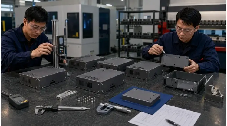
Pilot Enclosures at Final Inspection
Design Revisions and Sample Approval
Version control is a common failure point when transitioning from prototype to production. If the engineering team updates a hole location but the procurement team re-orders using the original Rev A drawing, the entire batch will be rejected.
Establish a strict, closed-loop revision process:
Issue Logged → Root Cause Analyzed → CAD Updated → 2D Print Updated → New Sample Built → Retested → Formally Approved.
Before triggering a production run, ensure the following assets are locked and archived in a centralized system:
The final issue log detailing all resolved defects.
The updated 3D model and 2D drawing (with matching revision numbers).
The final FAI and functional test reports.
A physical Golden Sample. This is an approved, signed-off prototype kept at the factory as the ultimate visual and physical reference to resolve any future quality disputes on the assembly line.
The official production revision number.
Production Tooling and Process Controls
Scaling from 5 prototypes to 5,000 units requires a shift in manufacturing strategy. The tool-free methods used for prototyping are rarely the most economical choice for mass production. Depending on the volume, production routes include:
Low Volume: Continuing with laser cutting and CNC press brakes.
Process Stabilization: Adding custom welding fixtures or dedicated bending jigs to improve repeatability.
Medium Volume: Transitioning flat patterns to a CNC turret punch for faster throughput.
High Volume: Investing in single-stage stamping dies or progressive dies to eliminate manual bending entirely.
Automation: Implementing robotic welding cells or automated hardware insertion.
For procurement managers, the decision to invest in hard tooling (stamping dies) comes down to a strict break-even analysis. Use this formula to determine if the tooling investment is justified:
Break-even quantity = Tooling cost/(Prototype unit cost – Production unit cost)
Financial Example: If a stamping die costs $10,000, but reduces the unit price from $15 (laser cut) to $5 (stamped), your break-even point is exactly 1,000 units. If your annual forecast is only 800 units, stick to sheet metal fabrication.
Beyond the math, you must also consider design stability. If the product is still likely to undergo design changes in the next 12 months, investing in hard tooling introduces significant modification risks. In those cases, staying with laser-cut sheet metal is the safer financial strategy.
Once the fabrication route is chosen, the final step before mass production is executing a Pilot Run.
Warning: Never skip the Pilot Run. Scaling directly from 5 hand-tweaked prototypes to 5,000 mass-produced units without a 50-unit pilot run is the most common cause of catastrophic assembly line halts.
This small-batch run validates the production-level controls, including gauge confirmation, control plans, sampling plans, statistical process control (SPC/Cpk) metrics, and—if required by the industry—a full Production Part Approval Process (PPAP) package.
Conclusion
The true value of a sheet metal prototype does not come from simply acquiring a fast metal part. Its value lies in its ability to expose design flaws, assembly interferences, and manufacturing bottlenecks early, preventing catastrophic financial losses during mass production.
Ready to move from CAD to production? Send your 3D model, 2D drawing, material, finish, and quantity. Even if your design isn’t 100% locked, our engineering team will provide DFM feedback and a realistic sheet metal prototype quote to keep your project moving.
Wonderful! Share this Case:
Table of Contents
Send Your inquiry
Kevin Lee
Kevin Lee has over a decade of experience in the sheet metal industry, specializing in precision fabrication and problem-solving. With a strong focus on quality and efficiency, he brings valuable insights and expertise to every project, ensuring top-notch results and customer satisfaction in all aspects of metalworking.

 English
  Spanish
  German
  Russian
  Italian
  French