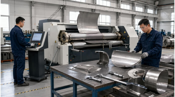
Sheet metal roll bending is a cold forming process that uses three or four adjustable rollers to continuously bend flat metal plates into cylindrical, conical, or large-radius curved shapes. It is the most efficient method for producing smooth metal arcs without the facet lines of press brake forming.
For engineers, specifying large-radius curves or cylindrical parts often presents a manufacturing challenge: how to achieve a smooth, continuous radius without inflating fabrication costs. While a standard press brake handles sharp angles perfectly, forcing it to create sweeping arcs via bump bending wastes machine time and compromises surface aesthetics.
This guide breaks down the mechanics of the rolling process, compares the capabilities of 3-roll and 4-roll machines, and provides actionable Design for Manufacturability (DFM) rules. Understanding these parameters will help you control material springback, reduce flat-end waste, and optimize your overall production costs.
Capabilities and Common Applications
Roll bending applies uniform pressure across the material surface. This makes it suitable for specific geometries that are difficult or inefficient to produce using standard press brake tooling.
Smooth Curves
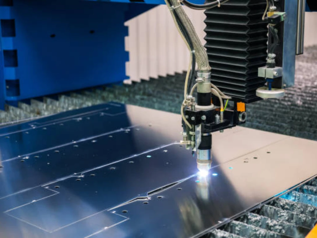
The process works well for parts that require continuous, sweeping arcs. Unlike bump bending on a press brake, which creates a curve through a series of small, distinct angles, roll bending produces a smooth surface finish. This continuous forming is usually used for aerodynamic components, fluid flow channels, or architectural panels where aesthetic and functional continuity is necessary.
Cylindrical Shells
Roll bending is commonly used to manufacture cylindrical enclosures, pressure vessels, and storage tanks. By adjusting the roller positions, manufacturers form closed cylinders from metal plates, and the final edges are subsequently welded together.
The physical limit for a full cylinder depends on the machine’s top roll diameter, as the formed tube must be able to slide off the equipment after rolling. Additionally, the ability to successfully form a complete shell depends heavily on the material’s yield strength and the diameter-to-thickness ratio.
Curved Covers
For industrial equipment, curved metal covers provide structural rigidity and protective housing. Roll bending efficiently processes thin to medium-gauge sheet metal—typically ranging from 1mm to 6mm—into machine guards, engine cowlings, or heavy-duty casings.
Tube and Profile Parts
While generally associated with flat sheet metal, roll bending principles also apply to structural shapes. Using specialized grooved dies, the process can bend square tubing, round pipes, and extruded profiles without collapsing the internal walls.
Proper tooling is critical here. The right groove setup prevents wrinkling on the inside radius or flattening on the outside wall, which are the most common and costly defects in profile rolling.
Large-Radius Parts
When a part requires a large, uniform radius, roll bending becomes more cost-effective at volume compared to press brake forming. Press brakes require either expensive custom punch-and-die sets for large radii or time-consuming bump bending operations involving dozens of individual strokes.
Roll machines, in contrast, adjust to various large radii without requiring physical tooling changes. This flexibility significantly reduces machine setup and execution time per part.
Process Mechanics and Setup Variables
Achieving a precise curve depends heavily on the initial machine configuration and how the operator accounts for the behavior of the specific metal batch.
Roller Pressure
The final radius is determined by the geometric arrangement of the rollers and the pressure applied. In a standard setup, the material is pinched between a top and bottom roller, while side rollers move upward to push the metal into a curve.
Adjusting this pressure requires precision. Minor variations in plate thickness or material hardness from batch to batch can cause inconsistent radii if the machine pressure is not calibrated correctly.
Multiple Passes
Rolling a part to its final dimension in a single pass is not always possible or recommended. For thicker materials, tight radii, or high-yield-strength metals, the sheet is usually passed through the rollers multiple times.
This incremental approach reduces the strain on the machine’s hydraulic system and prevents surface micro-cracking. Avoiding micro-cracks is especially critical for materials with aesthetic finish requirements, such as brushed stainless steel.
Pre-Bending
Pre-bending is a necessary preparation step where the very ends of the sheet metal are clamped and bent before the main body of the plate is rolled.
Without this step, the rollers cannot effectively grip and bend the extreme leading and trailing edges. Failing to pre-bend results in a formed part that resembles a teardrop rather than a true cylinder.
Flat Ends
Even with careful pre-bending, roll-bent parts often retain a small, unbent flat section at the very edges. The length of this flat end depends on the mechanical distance between the machine’s pinch rolls. On modern equipment, this straight section is typically reduced to 1.5 to 2 times the material thickness.
If the engineering drawing requires a perfect curve all the way to the edge, manufacturers usually process a slightly longer metal blank and trim the flat ends off after rolling. Designers should account for this extra material yield loss when calculating raw material costs for tight-tolerance true cylinders.
Springback
When the part exits the rollers, the metal naturally attempts to return to its original flat state due to elastic recovery. To achieve the specified dimension, the metal must be intentionally over-bent to a tighter radius so it relaxes into the correct shape.
The severity of springback depends heavily on the material. For example, 5052 aluminum has relatively predictable springback, whereas 304 stainless steel experiences significant work hardening, requiring much more over-bending and machine tonnage. While CNC machines use material data libraries to calculate this compensation, strict-tolerance jobs still rely on running test pieces to establish exact parameters.
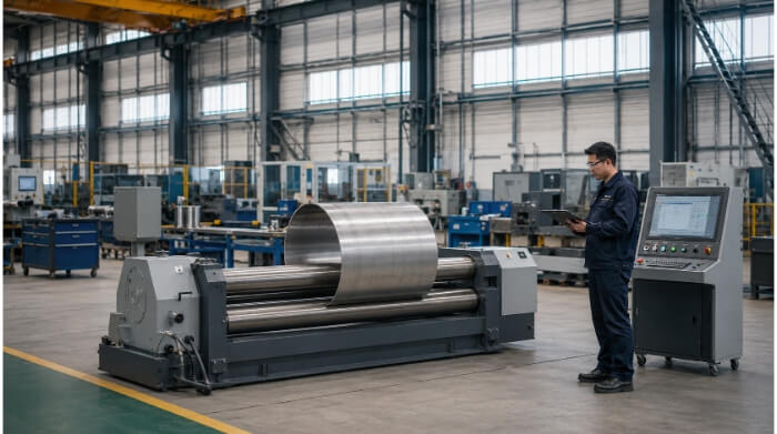
Equipment Selection: 3-Roll, 4-Roll, and CNC
Selecting the appropriate equipment dictates the speed, precision, and ultimate cost of the rolled part. While manual machines work for low-volume structural work, tight-tolerance components require advanced configurations.
Three-Roll Bending
Three-roll machines are the traditional standard in many fabrication shops. In a standard asymmetrical setup, the top and bottom rolls pinch the material while the third roll moves to dictate the radius.
While three-roll bending involves a lower initial equipment cost, it requires more manual intervention. Operators must often remove, flip, and re-insert the plate to pre-bend both ends. This extra handling significantly increases labor time per part.
Four-Roll Bending
Four-roll machines offer a significant mechanical advantage. The plate is securely clamped between the top and bottom central rolls, while the two side rolls independently move up to form the curve.
This configuration allows operators to pre-bend both the leading and trailing edges without removing the material. For mass production where precise alignment is critical for downstream automated welding, four-roll bending provides exceptional repeatability and eliminates slipping during the process.
CNC Roll Bending
Integrating Computer Numerical Control (CNC) into rolling machines shifts the process from an operator-dependent craft to a data-driven manufacturing method. The engineer inputs the material type, thickness, and target radius, and the system calculates the required roller positions.
For volume production runs, CNC control ensures that the 100th piece matches the exact dimensions of the first piece. It safely manages multi-pass rolling for complex geometries like ellipses or varying-radius cones without relying on guesswork.
Bump Bending
Bump bending uses a standard press brake and V-die to create a curve through a series of closely spaced, small-angle bends. It is not true roll bending, but it is the most common alternative when a shop lacks rolling equipment.
While bump bending is cost-effective for 1 to 5 prototypes because it uses standard tooling, its efficiency drops significantly for production runs over 50 units due to the immense setup and execution time. Additionally, it leaves visible facet lines across the surface, which is usually unacceptable for fluid dynamics or cosmetic applications.
Machine Capability Assessment
| Process | Setup Time | Pre-bending Capability | Volume Production Suitability |
| 3-Roll Bending | Moderate | Requires manual flipping of the plate | Low to Medium |
| 4-Roll Bending | Fast | Single-pass clamping at both ends | High (Excellent repeatability) |
| Bump Bending | Very High | N/A (Step-by-step process) | Very Low (1-5 Prototypes only) |
Roller Deflection and Crowning
Every roll bending machine has strict capacity limits defined by material width, thickness, and yield strength. High-strength alloys require significantly more machine tonnage to form.
Pushing a machine beyond its rated capacity will cause the steel rollers themselves to deflect, or bend slightly in the middle. This results in a cylinder that is tighter on the ends and barrel-shaped in the center. To counteract this on thick plates, high-end machines utilize “crowning”—rollers machined with a slight convex profile, or dynamic hydraulic compensation—to ensure uniform pressure across the entire width.
Material Limits and DFM Guidelines
A successful roll bending project starts in the CAD software, long before the metal reaches the shop floor. Designing for manufacturability (DFM) minimizes scrap rates and prevents unexpected fabrication bottlenecks.
Material Behavior
Different metal alloys behave radically differently under rolling pressure. Standard carbon steel (like Q235 or A36) forms predictably and requires relatively low tonnage.
In contrast, aluminum alloys vary strictly by temper. A soft 5052-H32 aluminum rolls smoothly, while a rigid 6061-T6 is highly prone to cracking along the bend axis. Stainless steel work-hardens rapidly as it deforms, meaning it requires increasingly more force with each pass through the rollers.
Minimum Radius
Pushing a material to a radius smaller than its physical limits causes the outer surface to stretch and fracture.
As a general rule of thumb, the minimum internal rolling radius should be at least 1.5 to 2 times the material thickness for mild steel. For high-strength alloys or thick plates, this ratio increases. If a tighter radius is required, designers should consider using seamless metal tubing instead of rolling flat sheet metal.
Holes and Cutouts
Features like holes, slots, or laser-cut patterns create weak points in the metal. If these features are located on or near the rolling curve, the pressure of the rollers will stretch them out of tolerance, turning circular holes into ovals.
To prevent distortion, holes should be kept well away from the curved sections. If functional cutouts must exist on the curve, the factory must roll the solid sheet first, and then cut the features using a 5-axis laser or CNC mill. Designers must be aware that this adds secondary routing time and significantly increases the per-part cost.
Weld Seam Position
Sometimes, flat plates are welded together before rolling to create an oversized blank. A weld seam is structurally different from the base metal—it is generally harder, thicker, and less ductile.
Rolling directly across a weld seam can cause the curve to flatten out at the joint or even damage the machine’s rollers. Designers should plan the flat blanks so that any necessary weld seams run parallel to the rolling axis. The factory must also grind these seams perfectly flush before forming.
Surface Marks
The rollers exert immense pressure to permanently deform the metal. Any dirt, metal scale, or debris left on the rollers will be pressed directly into the part’s surface, causing permanent pitting.
For parts requiring a pristine cosmetic finish, factories often use specialized urethane-coated rollers to protect the metal. However, this creates a distinct manufacturing trade-off: the urethane compresses under pressure. This not only reduces the machine’s maximum bending force but also slightly reduces radius precision compared to bare steel rollers.
Cost Drivers and Tolerance Control
A precise manufacturing quote relies on clear engineering drawings. Vague tolerances or missing material specifications lead to inaccurate cost estimates and unexpected delays on the shop floor.
Setup Time
Machine setup is the largest cost driver for low-volume roll bending orders. Operators must adjust roller positions, calibrate pressure, and often run test pieces to dial in the exact springback compensation.
For a batch of 5 parts, this setup time makes up the majority of the per-part cost. As volume increases to 500 or 5,000 units, the setup cost amortizes, making the individual unit price drop significantly. CNC machines further reduce this time for repeat orders by storing previous roll parameters.
Material Yield
Rolling often requires a slightly longer blank to account for unbent flat ends. If the final part must be a perfect curve from edge to edge, the factory must trim the excess material after rolling.
This trimming adds secondary processing time and increases the overall scrap rate. If the design can functionally accept a small flat section at the ends, explicitly stating this on the drawing reduces material waste and lowers the final price.
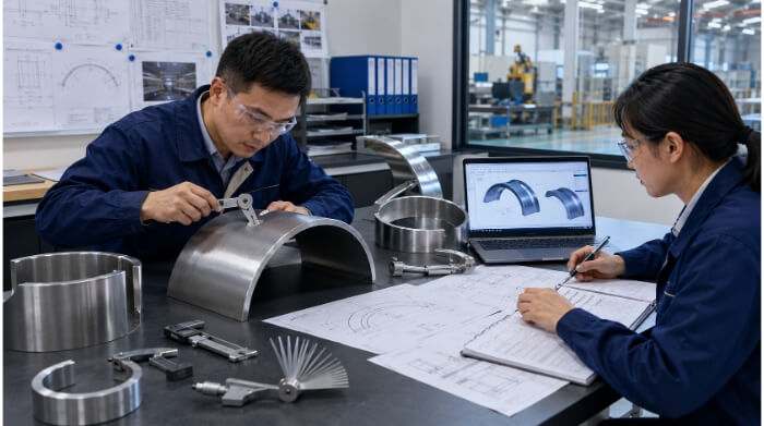
Radius Check
Tolerances determine the inspection method and time. Standard radius checks use physical sweep templates or radius gauges pressed against the inner curve of the formed part.
Specifying an unnecessarily tight radius tolerance requires the operator to make micro-adjustments and run additional passes. Designers should indicate which specific curved surfaces are critical for assembly and which are purely cosmetic to avoid unnecessary inspection costs.
Roundness Check
For full cylinders or pipes, measuring the radius alone is not enough. The factory must check the roundness, or ovality, by measuring the diameter across multiple axes using calipers or laser scanning.
If the cylinder is intended to slip over another machined component or requires automated orbital welding, roundness tolerances must be strictly defined. Often, thin-walled cylinders will flex under their own weight, requiring custom fixtures during the quality check to measure their true geometric state.
Conclusion
Roll bending provides a scalable, repeatable method for producing large-radius parts, structural curves, and cylindrical shells. Success depends heavily on understanding material behavior, designing around the physical limits of the rollers, and specifying functional tolerances.
At TZR, our engineering team brings 10 years of sheet metal fabrication experience to evaluate your CAD files and identify potential forming risks before production begins. Send us your 3D models and project requirements today to get a detailed technical quote and a free DFM review within 24 hours.
FAQs
What is the difference between roll bending and press brake bending?
Press brake bending uses a punch and V-die to create sharp, angular bends along a straight axis. Roll bending uses a set of adjustable rollers to apply continuous pressure, creating smooth, sweeping curves or complete cylinders. While a press brake can simulate a curve through a process called bump bending, it leaves visible facet lines, whereas roll bending creates a seamless arc.
Why do roll-bent parts have flat ends?
Flat ends occur because there is a physical distance between the machine’s pinch rollers. The extreme leading and trailing edges of the metal plate cannot be securely gripped and bent at the same time. This leaves a straight, unbent section at both ends, usually equal to 1.5 to 2 times the material thickness.
What affects the cost of roll bending?
The primary cost drivers are machine setup time, material type, and secondary operations. High-yield-strength metals like stainless steel require more machine tonnage and multiple passes, increasing labor time. Additionally, strict tolerances that require factories to trim off flat ends or cut holes after the rolling process (using a 5-axis laser) will significantly increase the per-part cost.
What information is needed for a roll bending quote?
To provide an accurate and fast estimate, please include the following in your RFQ:
- 3D CAD Models: STEP or IGES format to evaluate the geometry.
- 2D Drawings: PDF format highlighting critical radius tolerances and acceptable flat end limits.
- Material Specs: Exact alloy grade and temper (e.g., 5052-H32 Aluminum).
- Quantities: Expected production volume to determine the best machine setup and pricing tier.