
 English
 Spanish
 German
 Russian
 Italian
 French

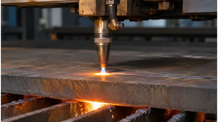
Oxy-fuel cutting is a thermal process that uses fuel gas and pure oxygen to heat and rapidly oxidize metal. It is exclusively used for cutting low-carbon and low-alloy steel plates between 10 mm and 300 mm thick, offering a highly cost-effective solution for heavy fabrication.
To understand how this process translates to your bottom line, consider a standard manufacturing routing: a 40 mm thick mild steel baseplate featuring four Ø18 mm mounting holes. A typical shop routes this by cutting the outer profile first, followed by CNC drilling the internal holes. We drill after cutting because thermal processes leave a hardened heat-affected zone (HAZ) on the edge that can instantly ruin drill bits.
To accurately evaluate how this outer profile should be cut and what your quote should include, let’s break down how the oxy-fuel method works and which drawing tolerances dictate your final process selection.
When to Choose Oxy-Fuel Cutting for Steel Plate?
Matching the cutting process to your part’s geometry prevents costly rework. Let’s explore how plate thickness and drawing tolerances dictate when oxy-fuel is your most cost-effective option.
Material and Plate Thickness
The oxy-fuel process is primarily used for low-carbon and low-alloy steels. The physical mechanism requires the metal to oxidize rapidly and the resulting oxide to have a lower melting point than the base material itself. This is why standard oxy-fuel equipment cannot cut stainless steel or aluminum; the refractory oxides formed on these metals prevent the oxygen stream from penetrating the material.
For carbon steel, oxy-fuel works well for plate thicknesses ranging from 10 mm up to 300 mm. The practical maximum thickness for a given project usually depends on the specific material grade, the shop’s gas supply volume, and whether the cut can start from an open edge or requires piercing through a solid plate.
Oxy-Fuel, Plasma, and Laser
Selecting the right thermal cutting process depends on plate thickness, feature geometry, and tolerance requirements. The table below outlines how these variables affect the initial process choice.
| Part Characteristics | Primary Process Evaluation | Drawing Requirements That May Change the Choice |
| Thick plate, simple outer profiles (>25 mm) | Oxy-Fuel or High-Definition Plasma | Standard cutting tolerances are ±1.5 mm to ±2.0 mm. Tighter perpendicularity requirements may push the process to CNC milling after rough cutting. |
| Thick plate with precision holes | Cut outer blank, drill holes secondary | If the hole diameter is less than the plate thickness (ratio < 1.0), thermal cutting causes excessive heat buildup, severe taper, and blowout at the bottom. |
| Thin plate, complex/dense contours (<10 mm) | Fiber Laser | Heavy rust or thick mill scale on the material may require plasma instead of laser. |
Returning to the 40 mm baseplate example, the outer profile is simple enough that both oxy-fuel and high-definition plasma are viable options for blanking. However, the four Ø18 mm holes have a diameter-to-thickness ratio of less than 1:1. Therefore, the RFQ should price the outer shape as a thermal cut, while routing the internal holes for secondary drilling.
How Piercing and Gas Choice Affect Production?
Shop floor execution directly impacts your final unit price and lead times. Here is how torch entry methods and fuel gas selection drive material yield and cut quality.
Edge Starts and Plate Piercing
How the torch enters the material affects cutting time, nesting efficiency, and final part cost. Starting the cut from the outer edge of the plate is the most stable method, as the preheat flame can quickly bring the exposed corner to kindling temperature and allow the oxygen stream to pass through cleanly.
Piercing—starting a cut in the middle of a solid plate for an internal cutout—takes longer and risks blowing molten steel slag back into the torch nozzle. Internal piercing requires a lead-in path to prevent the initial molten blowout from damaging the final part edge. This means the nesting layout must leave enough scrap space between parts, which reduces material yield. When comparing quotes, it is important to confirm whether the supplier is routing the part with edge starts or internal piercing, and whether secondary operations like dross removal and edge flattening are explicitly included in the unit price.

Preheat Fuel and Cutting Oxygen
The choice of preheat gas directly impacts preheat time, continuous cutting speed, and overall gas consumption.
- Acetylene produces the highest flame temperature (approx. 3,160°C). It requires less preheat time and pierces faster, making it suitable for nests containing many small, enclosed internal cutouts where the torch must start and stop frequently.
- Propane burns at a lower temperature (approx. 2,828°C) and requires longer preheat times. However, it often produces a cleaner cut edge and becomes more cost-effective at volume for continuous cutting on long, uninterrupted profiles. For our 40 mm baseplate example, an edge-started propane cut would likely offer the best balance of edge quality and processing cost.
Regardless of the fuel gas used, cutting oxygen purity requires strict control. A drop in oxygen purity from 99.5% to 98.5% may decrease cutting speeds by up to 25% and increase gas consumption proportionally.
Safety and Shop Controls
Oxy-fuel cutting involves intense localized heat and generates heavy slag. Standard shop procedures require downdraft tables or specialized fume extraction systems to manage particulate emissions, especially when cutting primed plates.
For operational safety, gas delivery systems are required to have flashback arrestors installed at both the regulator and torch ends to prevent reverse gas flow, in strict accordance with local hot-work regulations and equipment manuals.
What to Specify on the Part Drawing?
Clear drawing annotations prevent miscommunication between the design team and the fabrication floor. Here is exactly what to call out before requesting a thick-plate quote.
Holes, Slots, and Inside Corners
Small holes, narrow slots, and sharp inside corners in thick plate require confirmation before quoting. Using our 40 mm baseplate example, the four Ø18 mm mounting holes and their positional datums must be clearly marked. If your project routes these features for secondary CNC drilling, explicitly state “Cut outer profile, drill internal holes” on the RFQ to avoid receiving a non-compliant, thermal-pierced quote.
Machining Allowances and Datums
A fabrication drawing must distinguish between the raw blank size and the finished machined size. Clearly indicate which edges remain as-cut, which edges require excess material (machining allowance)—typically 3 to 5 mm to ensure the milling cutter bypasses the heat-affected zone (HAZ)—and the exact datums used for positioning the drill or mill. If your project adheres to international thermal cutting standards, add a note citing the specific ISO 9013 tolerance class (e.g., Class 2 for perpendicularity).
Weld Bevels
If the part requires edge preparation for welding, detail the V-groove or Y-groove geometry, specifically calling out the bevel angle and the root face dimension. Ask the supplier to confirm if these bevels can be cut directly on their multi-axis oxy-fuel machine or if they require secondary bevel milling and grinding before delivery.
How to Inspect the Part and Troubleshoot Cut Defects?
Standardizing your inspection routine catches thermal distortion and parameter errors early. Use these frameworks to structure your first-article checks and identify the root causes of cut defects.
First-Part Inspection
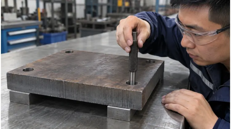
A First Article Inspection (FAI) on a thick plate part should be divided by manufacturing stages to catch errors before downstream value is added. Here is a standard first-article inspection checklist for oxy-fuel cut parts:
| Inspection Item | Measurement Reference & Tool | Timing / Stage |
| Outer profile & allowance | Drawing outer edges (Calipers / Tape Measure) | After oxy-fuel blanking |
| Edge perpendicularity | ISO 9013 Class 2 (Machinist’s Square / Feeler Gauge) | After oxy-fuel blanking |
| Hole diameter & position | Machined datums (Pin gauges / CMM) | After CNC drilling |
| Overall part flatness | Surface plate | Final delivery state |
Rounded Edges, Drag Lines, and Dross
Evaluating the as-cut edge reveals how well the gas parameters and feed rates are dialed in. Common visual defects include top-edge rounding, deep drag lines, and heavy bottom dross (slag accumulation). Use this oxy-fuel cutting troubleshooting matrix to correct defects:
| Defect Manifestation | Primary Diagnostic Checks | Trial Cut Adjustments |
| Heavy bottom dross (slag) | Cut speed, cutting oxygen pressure, nozzle condition | If dross is hard to remove, increase cut speed or adjust oxygen pressure until dross clears. |
| Deep drag lines lagging behind | Travel speed (too fast), oxygen flow (too low) | Reduce travel speed; verify oxygen supply pressure at the torch. |
| Top-edge melting / rounding | Torch height, preheat flame intensity | Lower preheat oxygen/fuel ratio; increase standoff distance slightly. |
Edges for Welding and Machining
The physical state of the cut edge determines the success of downstream operations. For milled edges, the first-part inspection must confirm the exact machining allowance—too little scrap risks tool damage on the hardened edge, while too much increases cycle time. For weld bevels, verify the angle and ensure the cut surface is free from deep gouges that could cause slag inclusions during welding.
If your project specifies a maximum edge hardness limit—often required because rapid cooling creates a hard martensitic skin on the cut edge—list it as a separate acceptance criterion, noting the specific steel grade and plate thickness tested.
How to Compare Quotes for the Finished Part?
Evaluating a thick-plate quote goes beyond looking at the bottom-line price. Let’s break down how to uncover hidden routing costs and ensure true apples-to-apples vendor comparisons.
Quote Scope and Delivery Condition
When reviewing quotes for our 40 mm baseplate, you must compare the exact scope of work. A lower unit price might exclude critical secondary steps. Place an oxy-fuel routing next to a plasma routing and verify that both vendors are quoting the identical final delivery condition.
| Process Step | Quote A Routing (Oxy-Fuel + Drill) | Quote B Routing (Plasma + Drill) |
| Material | Included (e.g., ASTM A36) | Included (e.g., ASTM A36) |
| Blanking Method | Oxy-fuel (Edge start) | High-Definition Plasma |
| Dross Removal | Included (Manual grinding) | Included (Automated brushing) |
| Part Flattening | Not included (Hidden risk) | Included (Roller leveling) |
| CNC Drilling | Included (4x Ø18 mm) | Included (4x Ø18 mm) |
| Final Inspection | Included (FAI + Material Certs) | Included (FAI + Material Certs) |
Cost per Accepted Part
Evaluate the total price based on the same drawing revision, batch size, and acceptance criteria. To find the true cost, divide the total lot cost by the number of accepted parts, not just the raw blank quantity. A cheaper raw-blank price is useless if a 10% scrap rate halts your assembly line.
What actually drives the price difference is often hidden in the routing details. For example, oxy-fuel introduces significant heat into the plate. If that thermal input causes the baseplate to warp out of your flatness tolerance, the oxy-fuel routing will require a secondary roller leveling operation. If the supplier did not include leveling in Quote A, the initially cheaper cutting rate will result in expensive rework or rejected parts at your dock.
RFQ Checklist
Use this copy-pasteable checklist in your next Request for Quote (RFQ) to force suppliers to clarify their manufacturing routing and confirm the final delivery state.
- Material Grade & Thickness: (e.g., 40 mm ASTM A36 or S355)
- Order Quantity & Batch Size:
- Drawing Version: (Always attach both the PDF and DXF/STEP files)
- Critical Features: (e.g., “4x Ø18 mm holes – Drill only, do not thermal pierce”)
- Machining Allowances: (e.g., “Leave +5 mm on Edge A to bypass HAZ for CNC milling”)
- Weld Bevels: (Specify angle, root face, and acceptable cutting method)
- Post-Processing Scope: (Specify requirements for dross removal, edge deburring, and surface flattening)
- Inspection Requirements: (e.g., FAI report, material certs, ISO 9013 Class 2 tolerances)
- Supplier Action Item: Please explicitly state the planned cutting method and list all included secondary operations in your itemized quote.
Evaluating a thick-plate cutting project? Send your drawings to TZR. Our engineering team will review your tolerances and provide a transparent, itemized cost comparison between oxy-fuel and plasma routing within 24 hours.