Choosing the right joining method for sheet metal is not a matter of preference; it is a structural and economic calculation. The decision between welding and riveting determines the assembly’s load capacity, the production bottleneck on the factory floor, and the final cost per part.
Welding fuses materials into a single, continuous structure, ideal for heavy loads and strict sealing requirements. Riveting relies on mechanical fasteners to lock overlapping sheets together, providing a cold-process solution that avoids material distortion.
Making the wrong choice early in the design phase can lead to warped thin sheets, failed field vibration tests, or unnecessary secondary finishing costs. This guide breaks down the engineering realities of both processes to help you specify the right joint for your assembly.
Welding vs Riveting at a Glance
There is no universally “better” process between welding and riveting. The optimal choice is strictly determined by the part’s function, the materials used, and the production environment.
Welding Forms a Continuous Joint
Welding applies intense heat to melt the base metals (often with a filler material), fusing them into one continuous piece. It is the go-to process when an assembly requires maximum rigidity, permanent structural strength, or absolute liquid and gas sealing.
Riveting Forms a Mechanical Joint
Riveting is a cold-forming process. It involves punching or drilling holes, inserting a fastener, and deforming the rivet’s tail to secure the metal sheets. It is highly efficient for joining thin-gauge metals, heat-sensitive materials, and dissimilar metals that cannot be melted together.
The Right Choice Depends on the Part Function
Engineers must evaluate the trade-offs. A welded joint offers a seamless cosmetic finish but requires skilled labor and risks thermal distortion. A riveted joint is fast and highly repeatable, but it leaves visible fastener heads and requires overlapping flanges.
Table 1: Quick Selection Guide
| Requirement | Better Choice | Reason |
| High structural strength | Welding | Forms a continuous joint |
| Leak resistance | Welding | Can create sealed seams |
| Thin heat-sensitive sheets | Riveting | Avoids welding heat distortion |
| Mixed materials | Riveting | No melting of base metals |
| Clean outer surface | Welding | No visible rivet heads |
| Easy repair | Riveting | Rivets can be removed and replaced |
| Coated or galvanized sheets | Riveting | Reduces coating damage |
What Changes When You Weld or Rivet Sheet Metal?
The physical behavior of a sheet-metal assembly changes significantly depending on how the joints are formed. Understanding these mechanical differences is critical for preventing premature failure in the field.
Strength and Load Path
A properly executed weld distributes mechanical stress continuously across the entire length of the seam. The welded joint is often as strong as, or stronger than, the base metal itself.
In contrast, riveted connections transfer loads through specific, isolated points. Drilling or punching holes for rivets inherently removes material, reducing the sheet’s cross-sectional area and creating localized stress concentrations at the hole edges.
Fatigue Life Under Vibration
Rigidity is not always an advantage. In environments with high-frequency vibration—such as automotive chassis, transport enclosures, or heavy machinery—a highly rigid weld can be a liability. Constant cyclic loading can cause microcracks to form and propagate through the brittle heat-affected zone of the weld.
Riveted joints possess a degree of micro-flexibility. This allows the assembly to absorb and dissipate vibration energy slightly, often resulting in a longer fatigue life under dynamic loads.
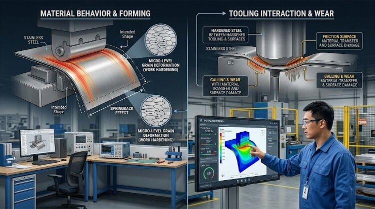
Heat Input and Thin Sheet Distortion
Welding generates a Heat-Affected Zone (HAZ) that alters the microstructure of the surrounding metal. When welding thin materials—such as 1.2mm Aluminum 5052 or 1.0mm Stainless Steel 304—this intense, localized heat causes severe thermal expansion and contraction.
The result is warping, buckling, and occasional burn-through, which requires expensive manual straightening later. Riveting eliminates this risk, maintaining the precise geometry and flatness of thin-gauge sheets.
💡 Pro Tip: We often see design files where engineers specify full welds on 1.2mm aluminum enclosures to avoid visible fastener heads. In reality, the manual labor required to hammer out the heat distortion can easily drive unit costs up by 30% compared to a riveted design.
Material Compatibility and Corrosion Risk
Riveting is the standard solution for joining dissimilar metals, such as attaching a 6061-T6 aluminum panel to a carbon steel frame. However, this introduces a critical engineering trap: galvanic corrosion.
If a bare steel rivet is installed in an aluminum sheet and exposed to an electrolyte (like moisture), the metals will react. This causes the joint to corrode and fail rapidly, resulting in costly field recalls and warranty claims.
To succeed, riveted joints with dissimilar metals require proper isolation, such as dielectric coatings, zinc plating, or non-conductive washers. Welding avoids galvanic issues entirely because it is generally restricted to joining identical or highly compatible alloys.
Sealing and Visual Requirements
For applications requiring watertight or airtight enclosures, such as fluid tanks or outdoor electrical cabinets, a full, continuous weld is mandatory. Welding also allows for premium aesthetics; the weld bead can be ground flush and polished, becoming completely invisible after powder coating.
Riveting cannot provide a hermetic seal without the addition of secondary liquid sealants or gaskets. Furthermore, the rivet heads will always protrude, breaking the surface’s visual plane.
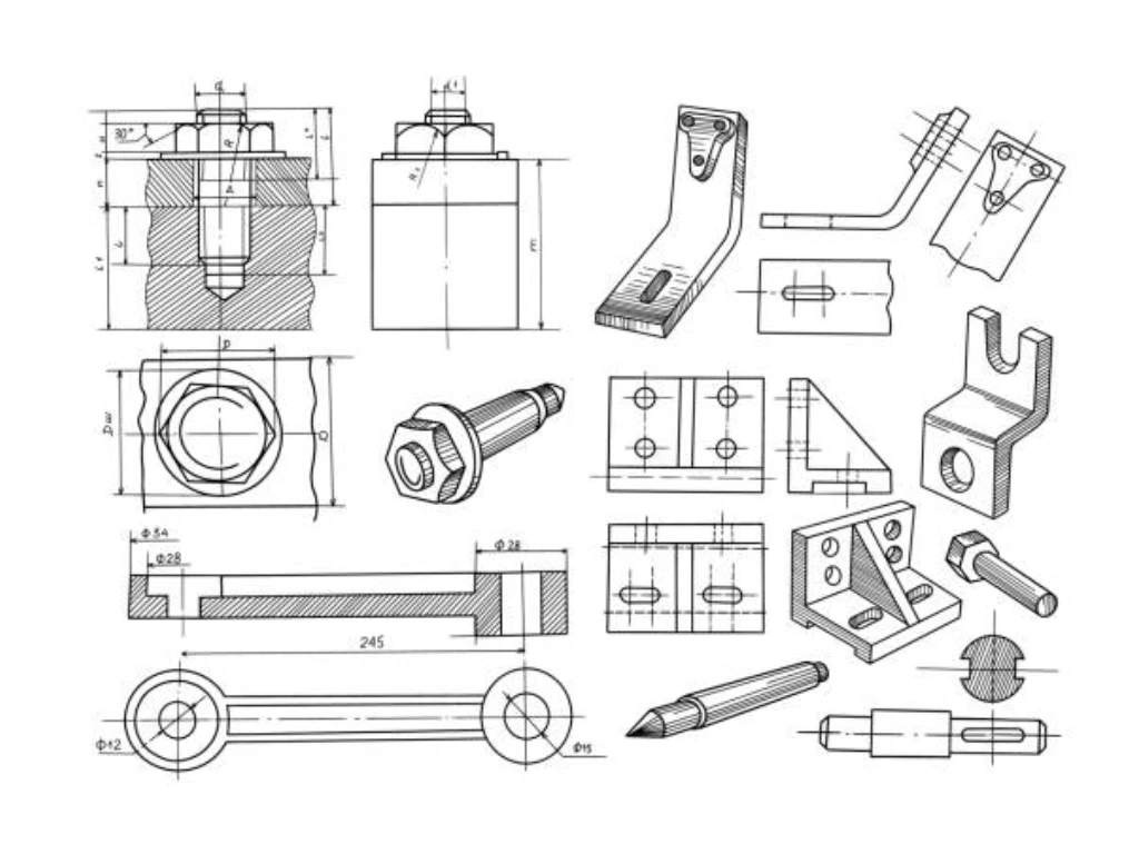
Design Rules That Affect Joint Quality
A joint is only as reliable as its design. Poorly designed welds or rivet placements do not just fail in the field; they cause immediate bottlenecks on the factory floor. Design for Manufacturability (DFM) means understanding the physical limits of the tools and the materials being used.
Rivet Hole Spacing and Edge Distance
Placing a rivet too close to the edge of a sheet metal part invites catastrophic failure. The clamping force and operational load can cause the metal to tear out or deform.
A standard manufacturing rule is to keep the center of the rivet hole at least twice the rivet diameter from the edge. Similarly, spacing rivets too closely together removes too much base material, severely weakening the flange’s overall shear strength.
Flange Width and Tool Access
Engineers often design tight corners in CAD, forgetting that a human operator needs physical space to insert a pneumatic rivet gun.
If a bending flange is too narrow (typically under 15mm for standard rivets), the nosepiece of the rivet gun cannot sit flush against the sheet metal. This results in angled rivets, loose joints, and scratched surfaces. Always check the clearance radius of standard riveting tools and design your flange widths to accommodate them.
Weld Length and Heat Management
Specifying a continuous, full-length weld on a long sheet-metal joint is rarely necessary for structural integrity and almost always results in severe warping.
Instead of a single continuous bead, seasoned engineers specify seam welding. For example, specifying a 25mm weld every 75mm provides excellent strength while allowing the heat to dissipate. This drastically reduces thermal distortion in materials like 1.5mm Cold-Rolled Steel (SPCC).
Tolerance Shift Post-Assembly
Welding inherently shrinks the metal as the weld pool cools and solidifies. This thermal contraction can pull the entire assembly out of tolerance, especially on large frames or precise enclosures.
Riveting locks parts into place exactly where the holes are aligned. Because CNC-punched or laser-cut pilot holes are incredibly precise, workers can use Cleco pins to lock large sheet metal parts together before riveting. This effectively makes the parts “self-fixturing,” ensuring the final assembly matches CAD dimensions without heat-induced shrinkage.
💡 Pro Tip: When designing a welded frame that requires tight tolerances for sliding internal components, we always build in a 1-2mm machining allowance. We weld the frame first, let the distortion settle, and then CNC mill the critical mounting points to the final exact dimension.
Cost, Lead Time, and Production Risk
Purchasing managers often focus on the raw cost of a rivet versus the cost of welding wire. This is a trap. The true financial difference lies in labor rates, surface preparation, fixture complexity, and the risk of scrapped parts.
Labor Skill and Automation Options
Manual welding requires highly trained, certified operators, making it one of the most expensive labor centers in a sheet metal factory.
Riveting is a standardized, highly repeatable process. Setting a pneumatic blind rivet takes 3 to 5 seconds and can be performed by operators with minimal training. By contrast, a 25mm TIG weld on stainless steel might take 45 seconds of arc time, plus setup and post-processing.
The Prototype-to-Production Bridge
In the prototyping and low-volume phase, riveting is king. Because parts are self-locating via pilot holes and Cleco pins, zero custom fixtures are required. You can iterate on designs rapidly at a low cost.
However, as you scale to mass production, the strategy often shifts to robotic spot welding or MIG welding. While this requires investing thousands of dollars in heavy, custom-machined welding jigs to prevent thermal warping, the fully automated speed and structural rigidity ultimately drive down unit costs at scale.
Hidden Cost in Weld Cleaning and Finishing
A weld is rarely finished when the torch is turned off. If the product requires a smooth cosmetic finish, operators must manually grind the weld flat, sand the area, and chemically clean the heat tint.
Grinding down and passivating a TIG weld on a Stainless Steel 304 enclosure often takes 2 to 3 minutes per joint—far longer than the welding itself. In a chassis with 50 connection points, this manual labor is a massive cost driver. Riveting requires zero post-processing. Once the rivet is popped, the part is ready for the next stage.
Surface Treatment Sequence
The manufacturing sequence dictates the joining method. Welding must be done on bare metal; you cannot weld over powder coating or heavy plating without creating toxic fumes and porous, weak welds.
Riveting can be done after the metal has been fully surface-treated. This is a major advantage when working with pre-galvanized sheets or pre-painted panels, as it preserves the factory-applied anti-corrosion coating in full.
Rework Risk and Assembly Tolerance
Mistakes happen on the assembly line. If a welded component is misaligned, correcting it requires destructive cutting, grinding, and starting over—often scrapping the part entirely.
Rivets offer a low-risk safety net. A misaligned riveted panel can have its rivets drilled out in seconds. The parts are cleanly separated, repositioned, and re-riveted with no damage to the base metal.
Table 2: Cost and Production Risk Breakdown
| Production Factor | Welding Impact | Riveting Impact |
| Operator Skill Level | High (Requires certified welders) | Low (Easy to train, standardized tools) |
| Upfront Fixture Cost | High (Needs rigid, custom clamping jigs) | Low (Self-locating via Clecos/pilot holes) |
| Post-Processing Labor | High (Grinding, sanding, acid cleaning) | Zero (Ready for immediate use or shipping) |
| Pre-Coated Materials | Cannot be used (Destroys coating, toxic fumes) | Excellent (Maintains factory coating integrity) |
| Cost of Rework | Very High (Destructive cutting required) | Very Low (Simply drill out the rivet) |
| Best Volume Fit | Mass Production (Justifies fixture automation) | Prototyping to High (Flexible and scalable) |
Where Each Method Fits in Real Sheet Metal Assemblies?
On the factory floor, the application dictates the process. Here is how seasoned manufacturing engineers apply welding and riveting across standard industrial product categories.
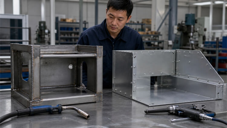
Electrical Enclosures and Control Cabinets
If the enclosure requires a strict environmental seal—such as an IP67 or NEMA 4X rating for outdoor or washdown environments—continuous welding is non-negotiable.
A control cabinet made from 1.5mm Stainless Steel 316L must be fully TIG-welded at the seams, ground flush, and passivated. Attempting to rivet an IP-rated enclosure requires secondary silicone sealants or heavy gaskets. These degrade under UV exposure and thermal cycling, ultimately leading to catastrophic water ingress and short circuits.
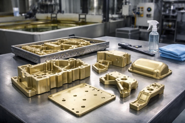
Telecom Cabinets and Pre-Coated Assemblies
5G telecom cabinets and outdoor HVAC units are often stamped from pre-galvanized sheet metal to prevent rust.
If you weld galvanized steel, the 3000°C arc instantly vaporizes the protective zinc coating, releasing toxic fumes and leaving the heat-affected zone completely unprotected. Unless the entire welded frame is sent out for expensive post-fabrication hot-dip galvanizing, that welded seam will rust within 6 months in a coastal environment. Riveting leaves the zinc layer 100% intact, making it the mandatory process for pre-coated materials.
Heavy Structural Brackets and Shipping Volume
When building load-bearing frames from 3mm to 6mm Q235 Carbon Steel, MIG welding provides the necessary shear strength to handle massive static loads. However, for cross-border supply chains, a 100% fully welded large frame means you are paying to ship empty air.
Smart procurement teams utilize a modular strategy. They TIG or MIG weld the critical, high-stress sub-assemblies in the factory, but design the main outer frame for assembly using heavy-duty structural rivets or bolts. This hybrid approach maintains the structural integrity of the Q235 steel while slashing ocean freight shipping volume by over 40%.
Deep Drawn Components and Residual Stress
In deep-draw metal stamping, the sheet metal undergoes extreme plastic deformation. This leaves massive internal residual stress within the walls of the drawn part.
If you apply intense welding heat to attach an internal bracket to a deep drawn shell, that stress is rapidly released. The housing will likely crack, warp, or pull entirely out of dimensional tolerance. For highly formed areas on deep-drawn parts, cold-forming processes such as blind riveting remain the safest engineering choice for attaching secondary components without compromising the primary geometry.
When Welding and Riveting Work Better Together?
The most common mistake junior engineers make is treating welding and riveting as a strict binary choice. In world-class hardware design, the best assemblies use a mixed-joining strategy.
The “Exoskeleton” Approach
A classic DFM strategy for industrial machinery is the “Exoskeleton” build.
Engineers will design a heavy internal structural frame using 2mm welded steel tubing to ensure absolute rigidity and vibration dampening. However, the outer cosmetic skins—often made of lightweight 1.2mm anodized aluminum—are attached to this welded frame using structural blind rivets or threaded inserts. This provides a heavy-duty core with perfectly flat, distortion-free aesthetic panels.
Welded Seams with Removable Service Panels
Permanent joints are a nightmare for field maintenance. If a fluid pump inside a fully welded tank fails, field technicians cannot bring an angle grinder and a TIG welder to the client’s facility to open and reseal the enclosure.
Smart assemblies use continuous welds for the primary containment body to ensure leak resistance, but utilize heavy-duty riveted or bolted flanges for the access panels. If a component fails, a technician can drill out the rivets in 10 seconds, replace the part, and install fresh rivets using a $50 hand tool—virtually eliminating factory downtime.
💡 Pro Tip: When designing a mixed-assembly outdoor enclosure, be wary of galvanic corrosion between the welded frame and the riveted panels. If you are riveting aluminum skins to a welded carbon-steel frame, always specify zinc-nickel-plated rivets or use nylon isolation washers. We’ve seen $10,000 electrical cabinets fail simply because a $0.05 bare steel rivet reacted with an aluminum door.
Conclusion
Welding and riveting are not competing methods. They solve different joining problems in sheet metal manufacturing. Welding is often better for strong frames, sealed seams, and clean outer surfaces. Riveting is often better for thin sheets, mixed materials, coated parts, and assemblies that may need repair or replacement.
Before choosing between welding and riveting, confirm the material, thickness, load requirements, surface finish, tolerance, and production quantity. If you are unsure which method fits your sheet metal assembly, send us your drawing. Our engineering team can review the joint design and suggest a practical manufacturing route.