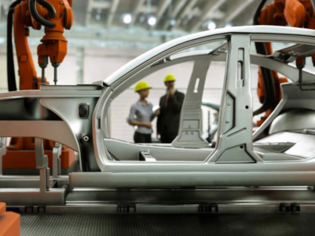
Tooling in manufacturing refers to custom physical devices—such as dies, molds, and fixtures—used to cut, shape, or hold raw materials. It replaces manual setups with fixed mechanical constraints, ensuring strict dimensional tolerances and predictable part costs during mass production.
Every custom part requires a specific tooling strategy. For engineering teams, tooling selection dictates the physical limits of the design and directly impacts surface finish and repeatability. For procurement managers, tooling represents a significant upfront capital investment and the primary factor in assessing a supplier’s production readiness.
This guide breaks down tooling from a practical manufacturing perspective. It covers the primary types of custom tooling, their direct impact on the cost per part, and the critical design for manufacturability (DFM) choices buyers and engineers must evaluate before authorizing a production run.
What Tooling Means in Manufacturing?
Tooling bridges the gap between raw materials and finished parts. Understanding its core function helps engineering and procurement teams make better manufacturing decisions.
Tooling Scope
In manufacturing, tooling refers to the specialized components, devices, and instruments required to produce a specific part. While machines provide the fundamental power and motion, tooling interacts directly with the raw material to shape, cut, or secure it.
The scope of tooling is broad. It ranges from standard end mills used in CNC machining to highly complex progressive stamping dies designed for general sheet metal fabrication.
Equipment vs Tooling
It is important to distinguish between manufacturing equipment and tooling. Equipment refers to the heavy machinery, such as a 5-axis CNC milling center or a 200-ton mechanical stamping press. These machines are universal assets and represent long-term capital expenses.
Tooling, conversely, is usually part-specific and acts as a custom constraint. A stamping press cannot produce a metal bracket without a custom die designed exclusively for that bracket’s specific geometry and material thickness.
Production Purpose
The primary purpose of tooling is to ensure repeatability and lock in dimensional accuracy. Relying on manual setup for every part is inefficient and prone to human error. Tooling transfers dimensional control from an operator’s manual adjustments to a fixed mechanical constraint.
This stabilizes the manufacturing process and helps keep scrap rates within acceptable limits across batches of 10,000 or more parts. Once a progressive stamping die is validated, the physical cost of producing the 10,000th part becomes highly predictable, allowing buyers to lock in a low cost per part for mass manufacturing.
Common Examples
Tooling takes different forms depending on the chosen manufacturing process. In sheet metal fabrication, tooling often means punch and die sets used for blanking and forming standard brackets, panels, or enclosures. In injection molding, it refers to the machined steel cavities.
In assembly and welding operations, tooling typically consists of custom workholding devices. These fixtures secure components in the correct alignment, which is critical to prevent heat distortion and maintain precise tolerances during the final build.
Main Tooling Types and Where They Are Used
Different manufacturing processes demand specific tooling solutions to ensure precision. Selecting the right physical tools prevents production bottlenecks and downstream quality issues.
Cutting Tools
Cutting tools are consumable items used primarily in subtractive manufacturing processes, such as CNC milling and turning. They include end mills, drills, taps, and turning inserts. These tools physically remove material from the workpiece to achieve the final shape.
Tool selection depends heavily on the workpiece material. For instance, machining cold-rolled steel or stainless steel usually requires carbide tooling with specialized coatings. This helps control tool wear and maintains surface finish over a long production run.
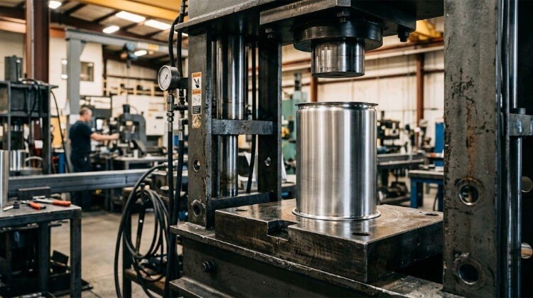
Dies and Molds
Dies and molds shape material through pressure or heat, rather than by cutting. A die is usually used in sheet metal stamping to shear, punch, or bend material. Because they require precise engineering and specialized machining, dies and molds often represent the highest upfront tooling cost in a project, sometimes ranging from $5,000 to over $100,000.
This investment is a one-time capital expense, but fixing a poorly designed die later is very expensive. Experienced engineering teams perform rigorous Design for Manufacturability (DFM) checks early on to optimize geometries, reducing the risk of costly die modifications and ensuring efficient production times.
Jigs and Fixtures
While often mentioned together, jigs and fixtures serve slightly different functions on the shop floor. A fixture securely holds the workpiece in a fixed position and orientation during machining, welding, or assembly. A jig also holds the part but actively guides the cutting tool.
Custom fixtures are generally necessary for parts with complex geometries that standard vises cannot hold. The speed at which a manufacturing team can design and machine these custom fixtures directly impacts how fast a new product can move from the drawing board to the first article inspection.
Inspection Gauges
Not all tooling is used to manufacture the part; some tooling is used to verify it. Inspection gauges are custom measurement devices used for quality control during production runs. Go/No-Go gauges, for example, allow machine operators to quickly check if a critical hole diameter falls within the acceptable tolerance band.
Using dedicated gauges is usually faster and more repeatable than relying solely on manual calipers. During high-volume production, where 100% inspection of certain features may be required, custom gauges prevent process drift and ensure defective parts do not reach the assembly line.
Tooling Strategy by Production Stage
Tooling needs evolve rapidly from initial prototypes to full mass production. Matching your tooling investment directly to your expected volume prevents wasted capital.
Soft Tooling
Soft tooling is usually used for early-stage design verification and rapid prototyping. These tools are typically machined from less expensive materials like aluminum or utilize silicone molds for urethane casting.
Because the material is easier to cut, soft tooling takes days rather than weeks to produce. The tradeoff is durability. Soft tools wear out quickly and are generally limited to runs of a few dozen to a few hundred parts, making them ideal for testing market fit before committing to a larger budget.
Bridge Tooling
Bridge tooling serves as a temporary production solution while the final, permanent tools are being manufactured. Making high-grade steel dies can take up to two months, so bridge tooling allows for early production runs and ensures timely delivery of initial orders.
These tools support volumes in the low thousands. More importantly, an engineering team with a decade of sheet metal fabrication experience can use this phase to anticipate forming risks, guaranteeing a smooth transition into full mass manufacturing without costly delays.
Production Tooling
Production tooling, or hard tooling, is built exclusively for mass manufacturing. These molds and dies are machined from hardened tool steels, such as P20 or H13, capable of withstanding extreme pressure and repeated impact over long periods.
While the upfront cost is substantial, hard tooling is a necessary investment for long-term consistency. A well-maintained hard tool can produce hundreds of thousands of parts with minimal dimensional variation, providing a highly trustworthy solution for high-volume production.
Volume Break-even
The decision to transition from soft to hard tooling depends heavily on the volume break-even point. This is the exact production quantity where the high upfront cost of a steel die becomes cheaper per part than continuing to use short-lived aluminum tools.
For 500 units, soft tooling is the economical choice. However, as production scales to 50,000 units, the initial investment in hard tooling becomes much more cost-effective. Engineering and purchasing teams must calculate this threshold together to establish competitive prices.
Cost Drivers Behind Tooling Investment
Custom tooling requires significant upfront capital, but several specific variables drive the final price. Evaluating these factors helps buyers negotiate effectively and control budgets.
Upfront Cost
The upfront cost covers the raw material of the tool block, the engineering design time, and the CNC machining required to cut it. Complex part designs directly require complex, expensive tools.
If a part has internal undercuts or side-facing features, the tooling will need movable sliding mechanisms. Adding these cams increases both the engineering hours and the machining time, which directly raises the initial invoice.
Unit Price
Tooling directly dictates the final unit price of the manufactured part through amortization. The total cost of the die is divided by the number of parts it produces over its lifespan.
For example, a $15,000 stamping die amortized over a 1,500-piece run adds $10.00 to the cost of each part. If that same die is used for a 150,000-piece run, the tooling cost drops to just $0.10 per part, justifying the upfront cost for mass production.
Material Wear
The material you choose for your final part heavily influences tooling costs. Tooling must be significantly harder than the workpiece material to prevent rapid deformation and maintain quality standards.
Stamping standard aluminum causes less abrasive wear on the die. In contrast, stamping high-strength stainless steel requires specialized carbide inserts and expensive surface coatings to prevent early failure, which drives up the tool’s price.
Tolerance Level
Tight tolerances act as a multiplier on tooling costs. If a drawing requires standard sheet metal tolerances, the toolmaker can use standard CNC milling to shape the die, but strict ±0.01mm tolerances require expensive, slow processes like wire EDM.
Reviewing drawings to remove unnecessary tight tolerances is the first step in providing a cost-effective solution. Keeping strict tolerances only on critical mating surfaces eliminates unnecessary machining hours and keeps pricing transparent and reasonable.
Tool Life
Tool life refers to how many cycles a tool can perform before it requires major refurbishment or complete replacement. Every tool requires preventive maintenance, such as sharpening cutting edges or repolishing mold cavities.
Buyers must discuss expected tool life with their manufacturing partners before production starts. A tool guaranteed for 50,000 cycles will cost less to build than one guaranteed for 500,000 cycles, but replacing a worn tool mid-production may cause severe supply chain disruptions.
Tooling in Common Manufacturing Processes
Every manufacturing method relies on distinct tooling setups to maintain shop floor efficiency. Understanding these process-specific applications helps teams optimize production workflows.
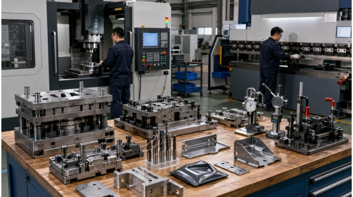
Stamping Dies
In sheet metal fabrication, progressive stamping dies are the standard for high-volume production. As the metal strip feeds through the press, multiple stations perform specific operations like punching and bending until the completed part is sheared off.
For early prototypes or runs of a few hundred parts, relying on laser cutting and CNC bending is a better choice because it requires zero custom tooling. However, once orders reach tens of thousands, the sheer speed of progressive stamping easily offsets the initial die cost.
CNC Workholding
For CNC machining, tooling primarily takes the form of workholding devices and custom fixtures. Standard vises cannot safely hold irregularly shaped parts without crushing them or allowing them to vibrate during the cutting process.
Machinists often design custom “soft jaws” out of aluminum to perfectly match the contours of the workpiece. This provides stable clamping pressure, which is critical for holding tight tolerances and preventing surface chatter during aggressive machining passes.
Welding Fixtures
Welding generates intense, localized heat, causing metal to expand and warp. Welding fixtures are heavily built clamps and frames designed to hold separate sheet metal components rigidly in place while the weld pool cools.
By restricting the metal’s natural tendency to pull or twist during cooling, welding fixtures prevent dimensional distortion. This ensures the final assembly meets the drawing’s geometric tolerances and provides a secure structural frame.
Assembly Fixtures
Assembly fixtures guide operators in putting parts together consistently. They remove the guesswork from manual assembly on the shop floor, ensuring every unit is built exactly the same way.
These fixtures often incorporate error-proofing features. For example, guide pins may be arranged so that a panel can only be inserted in the correct orientation. This prevents operators from installing parts backward and reduces the overall defect rate.
Quick-change Tooling
Machine downtime costs money. Setting up a heavy sheet metal stamping die or swapping out CNC fixtures traditionally takes hours, directly impacting the production schedule.
Quick-change tooling systems utilize standardized clamping interfaces to drastically reduce setup times. By allowing operators to load and locate tools in minutes, facilities can switch production lines faster, ensuring highly efficient production times.
How Tooling Controls Quality and Repeatability?
Consistent parts require rigid mechanical constraints to eliminate manual human error. Proper tooling locks in tolerances and maintains stable quality across massive production runs.
Part Location
CNC machines and stamping presses rely on exact starting coordinates. If a part moves during cutting or forming, the entire geometry shifts, resulting in a scrapped part.
Fixtures use hardened pins and nesting blocks to establish physical datums. This ensures every raw blank is positioned in the exact same orientation before the machine engages. Without strict location control, hole alignments will vary from batch to batch, causing major bottlenecks during final assembly.
Tolerance Control
Tight tolerances depend heavily on tool rigidity. If a cutting tool or holding fixture flexes under cutting pressure, the final dimension will inevitably deviate from the drawing.
Heavy-duty tooling absorbs machine vibration and resists deflection. This keeps the tool path true, preventing out-of-tolerance rejects that can hold up entire shipments and disrupt your supply chain.
Material Behavior
Raw materials react unpredictably to force, particularly in sheet metal forming. When metal is bent, it naturally attempts to return to its original flat state, a phenomenon known as springback.
Experienced engineers design stamping dies to over-bend the material by specific degrees. This engineered tooling geometry compensates for material springback. Without it, out-of-tolerance parts will fail to align during final assembly, leading to costly line stoppages and immediate part rejection.
Surface Finish
The physical condition of the tool directly transfers to the manufactured part. A poorly polished mold cavity or a rough stamping die will leave visible scratch marks on the finished surface.
Proper die clearance and specialized tool coatings prevent material galling and friction damage. This is crucial for stainless steel or aluminum enclosures that require a clean cosmetic finish straight off the machine, eliminating the need for expensive secondary polishing operations.
Process Drift
Even the hardest tool steel degrades after thousands of cycles. As cutting edges dull and locating pins wear down, dimensions slowly drift toward the edge of the acceptable tolerance band.
Routine dimensional checks and proactive tool maintenance prevent this drift. Resharpening a die or replacing worn fixture pins before they fail guarantees that the 10,000th part matches the first, securing your production timeline.
DFM Choices That Reduce Tooling Cost
Smart part design directly reduces the complexity and price of custom tooling. Small engineering adjustments can save thousands of dollars before manufacturing even begins.
Simple Geometry
Complex part geometries require complex, expensive tooling. Features like deep draws, severe undercuts, or non-standard angles force toolmakers to add movable sliding cams or multiple progressive stations.
Simplifying the part outline reduces the machining time needed to build the die. A straightforward bracket or panel design keeps the initial tooling invoice low and minimizes maintenance risks during production.
Standard Hole Sizes
Designers should match hole diameters to standard tooling sizes whenever possible. Specifying a 5.13mm hole means the shop must buy or grind a custom punch, increasing upfront costs and lead times.
Changing that dimension to a standard 5.0mm or 5.5mm allows the manufacturer to use off-the-shelf tooling. This single design change can shave two weeks off your lead time and eliminate custom punch fees entirely.
Uniform Bend Radius
Using multiple different bend radii on a single sheet metal part requires multiple tool changes. The press brake operator must stop the machine and swap out the punch and die for every different radius.
Standardizing the bend radius across the entire part allows the operator to form the piece in a single continuous setup. This cuts down on machine downtime, lowers the final cost per part, and accelerates the overall production schedule.
Bend Direction
Designing sheet metal parts with bends in the same direction simplifies the forming process. If a part has complex alternating bends, the operator must constantly flip and rotate the workpiece, which often requires complex custom backgauges.
Keeping bend directions uniform allows for simpler standard workholding. It makes the part easier to handle, leading to faster production speeds and lower defect rates.
Critical Tolerances
Applying strict tolerances across an entire drawing forces toolmakers to use slow, expensive manufacturing methods like wire EDM or surface grinding. It drives up the cost of the mold or fixture exponentially.
Engineers should restrict ±0.01mm tolerances strictly to critical mating surfaces or bearing fits. Allowing standard sheet metal tolerances for non-critical areas like external flanges keeps the tooling budget reasonable without sacrificing part function.
Conclusion
Tooling is not just a shop floor detail; it is a primary driver of unit cost, production speed, and quality control. Selecting the right tooling strategy ensures projects move smoothly from early prototypes to high-volume mass manufacturing. Poorly planned tooling, on the other hand, causes process drift, extends lead times, and blows budgets.
Evaluating tooling options requires experienced engineering support to balance upfront capital with long-term production goals. At TZR, our engineering team brings a decade of experience in sheet metal fabrication and CNC machining. We work directly with customers to optimize DFM, select the most cost-effective tooling strategy, and deliver high-quality parts on time.
Send us your CAD files today for a comprehensive DFM review, and let our engineering team show you where tooling costs can be minimized before you authorize the final production run.
FAQs
What is the difference between soft and hard tooling?
Soft tooling uses easily machinable materials like aluminum for low-volume prototypes and early design validation. Hard tooling is machined from durable tool steels (like P20 or H13) designed to withstand extreme pressure and hundreds of thousands of cycles for mass manufacturing.
Who owns the custom tooling after production?
In most manufacturing agreements, the customer retains ownership of the custom tooling once the upfront invoice is fully paid. The manufacturer stores, maintains, and operates the tooling at their facility for the duration of the production contract.
How much does sheet metal tooling usually cost?
Tooling costs depend entirely on part complexity, material hardness, and production volume. Simple press brake fixtures may cost a few hundred dollars, while complex progressive stamping dies for high-volume manufacturing can range from $5,000 to over $50,000.