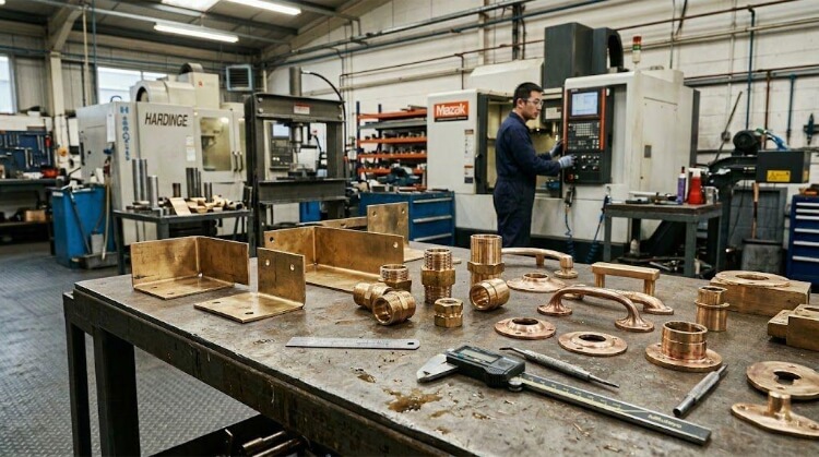
Deep drawing stainless steel delivers excellent durability and corrosion resistance for seamless hollow parts, but it presents immediate manufacturability challenges. It demands up to 50% more press tonnage than mild carbon steel, rapidly degrades unprotected tooling, and operates within a tight window between successful forming and catastrophic failure.
At TZR, when we see a deep-drawn part fail on the floor during the transition from prototyping to mass production, the root cause typically points to one of five engineering variables:
- Rapid work hardening
- Wall tearing and fracturing
- Flange wrinkling
- Accelerated tool wear (galling)
- Cost overruns from poor grade selection
The following outlines the exact material selection criteria, DFM rules to prevent defects, and the practical realities of keeping production stable and costs controlled during high-volume runs.
The Physics of Drawing Stainless Steel
The high tensile strength and robust oxide layer that make stainless steel desirable also make it hostile to cold forming. Controlling material flow under extreme high pressure is the primary technical hurdle.
Work Hardening
Austenitic stainless steels (like the 300 series) exhibit a specific metallurgical trait: as the metal deforms, its crystal structure partially transforms into martensite. This significantly increases both hardness and yield strength.
While beneficial for the final part’s structural rigidity, this rapid work hardening acts as a severe brake during the draw. Exceeding optimal press speeds or pushing a draw too deep turns the material brittle, leading to fracture. For extreme profiles—where depth exceeds diameter—the process requires intermediate annealing to reset the grain structure before subsequent draws.
Galling and Surface Scratches
Deep drawing generates extreme friction between the blank and the steel die. Under this pressure, the protective chromium oxide layer breaks down, allowing the bare metal to micro-weld to the die cavity—a failure mode known as galling.
Galling rips material from the part, causing deep surface scoring and destroying expensive tooling. High-volume runs require robust barriers: extreme pressure (EP) lubricants or dry film coatings applied directly to the blank. Additionally, the tooling requires advanced surface treatments, such as PVD (Physical Vapor Deposition) coatings, to survive thousands of cycles without seizing.
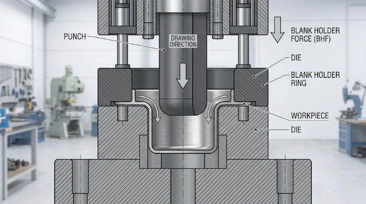
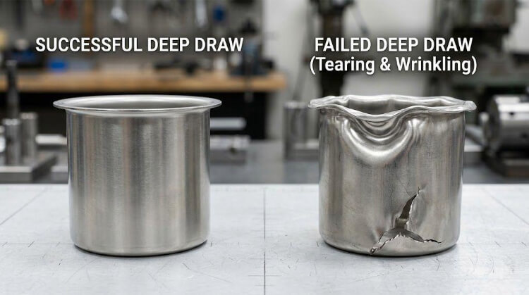
Wrinkling and Material Flow
As the blank is drawn into the die, radial compression forces the outer flange into a much smaller circumference. This compression naturally induces buckling and wrinkling.
To maintain sheet flatness, the press applies Blank Holder Force (BHF). This requires precise calibration:
- Insufficient BHF: Allows the flange to wrinkle and jam the die.
- Excessive BHF: Restricts flow, causing the punch to stretch and tear the bottom of the part.
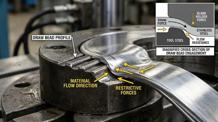
For complex geometries, we machine draw beads onto the binder ring. These ridges restrict flow in highly localized zones without requiring a universal increase in clamping tonnage.
Material Grade Selection for Deep Drawing
Grade selection dictates the entire tooling and production strategy. Specifying a grade with insufficient formability spikes scrap rates, while over-specifying inflates unit costs unnecessarily.
304 and 304L Stainless Steel
Type 304 is the industry baseline, suitable for roughly 80% of drawing applications. It balances corrosion resistance, yield strength, and formability for moderate draw ratios.
If the assembly requires secondary welding, specifying 304L is critical. The lower carbon content prevents carbide precipitation at the weld seam, eliminating localized corrosion risks in the field.
304DDQ (Deep Drawing Quality)
For aggressive single-stage forming, 304DDQ utilizes a higher nickel content to intentionally suppress the work-hardening effect. It allows the metal to stretch significantly further before reaching its fracture point.
Despite a higher raw material cost per kilogram, the ROI is often positive on the shop floor. If 304DDQ eliminates an intermediate annealing cycle or reduces a three-stage draw to two stages, the reduction in processing time and tooling complexity easily outweighs the material premium.
316 and 316L Stainless Steel
Containing molybdenum, Type 316 offers superior resistance to chlorides and harsh chemicals, making it mandatory for marine hardware and medical devices.
However, 316 is highly resistant to forming. It possesses a higher initial yield strength and work-hardens faster than 304. It requires higher press tonnage, accelerates die wear, and is susceptible to tearing at sharp radii. Specify 316 only when environmental factors strictly mandate it.
The Risk of Low-Cost Grades (200 Series)
Substituting lower-nickel alloys (like the 200 series) to reduce initial coil costs is a procurement trap. These budget grades possess inferior ductility and aggressive work-hardening rates.
Attempting to deep draw them guarantees frequent tearing, severe springback, and rapid tool degradation. Upfront coil savings are immediately negated by high scrap rates and press downtime.
DFM Rules That Prevent Deep Drawing Failures
A successful deep-drawn part originates in CAD, not on the press floor. Designing stainless steel components without accounting for the material’s physical limits guarantees high scrap rates and inflated tooling costs.
Limiting Drawing Ratio (LDR)
The absolute baseline metric for any cylindrical part is the Limiting Drawing Ratio (LDR). It dictates the maximum depth you can push the metal in a single stroke and is calculated as:
LDR = D_0/D_p
(Where D_0 is the flat blank diameter, and D_p is the punch diameter).
- Engineering Rule: For 304 stainless steel, the safe maximum LDR is 1.7 to 2.0.
- Cost Impact: If your design requires an LDR > 2.0, forcing it into a single-stage die guarantees bottom-tearing. You must transition to a multi-stage drawing process, which immediately doubles or triples your initial tooling investment.
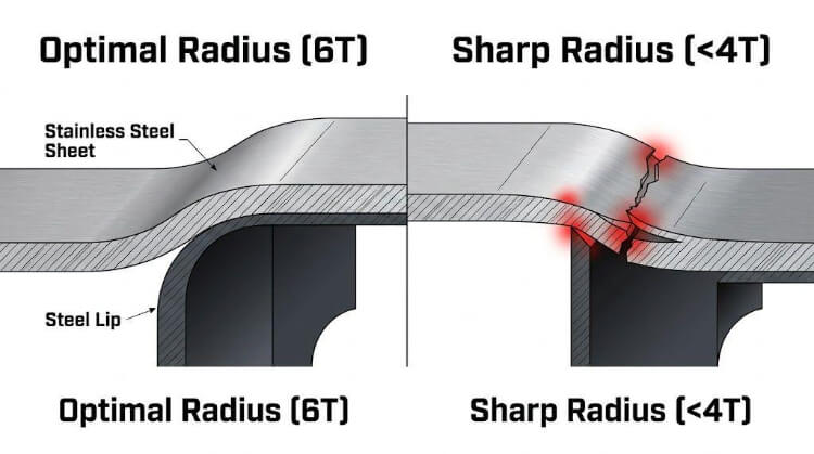
Punch and Corner Radii
Sharp internal corners act as massive stress concentrators. A die with insufficient radii stops forming the material and starts shearing directly through the stainless sheet.
- Engineering Rule: Maintain the punch radius (bottom corner) strictly between 4T and 10T (where T = Material Thickness).
- Shop-Floor Reality: If the radius is < 4T, the material thins out and fractures. If the radius is > 10T, you risk severe sidewall wrinkling because the material lacks tension as it flows over the die lip.
Asymmetrical Part Geometry
Perfectly cylindrical parts draw evenly. However, rectangular enclosures or asymmetrical shapes force material to pool and compress heavily in the corners, creating extreme localized stress.
- Engineering Rule: The total draw depth of a rectangular box should rarely exceed 5 times its corner radius.
- Design Solution: Maximize corner radii on your CAD models. If your product requires complex asymmetrical cutouts or high-precision side holes, utilize a composite manufacturing strategy: deep draw the main shell, and finish the complex features using 5-axis CNC machining or 3D laser cutting.
Multi-Stage Drawing Design
When a part’s depth exceeds LDR limits, the process requires progressive redraws.
- Engineering Rule: Successive draws must be progressively less aggressive to account for the material’s work hardening. A standard reduction sequence is 40% reduction on the 1st draw, 20% on the 2nd, and 15% on the 3rd.
- Cost Impact: Each stage requires a dedicated punch and die set. To avoid the high cost of a 3rd or 4th stage, introduce an intermediate thermal annealing step to reset the material’s grain structure, enabling a deeper secondary draw.
Why Deep-Drawn Parts Fail in Mass Production?
Prototyping a stainless part is a controlled process; mass-producing 100,000 units is an endurance test. High-volume failures rarely stem from the initial design—they are caused by the degradation of variables within the manufacturing environment.
Tool Wear & Galling
- The Pain Point: Scrap rates suddenly spike from 2% to 15% during week three of a production run, accompanied by deep scoring on the parts.
- The Root Cause: Stainless steel is highly abrasive. Continuous friction degrades standard die surfaces, causing microscopic cold welding (galling) between the sheet metal and the tooling.
- The Solution: Apply advanced PVD (Physical Vapor Deposition) or TD coatings to tooling, backed by a strict in-house maintenance schedule. Premium tooling eliminates weekly polishing downtime, bumping mass-production yields and driving down Total Cost of Ownership (TCO).
Coil Thickness Variation
- The Pain Point: Sudden press jams or unpredictable flange wrinkling on a previously stable line.
- The Root Cause: Raw material master coils inherently have gauge fluctuations. A 1.5mm thick 304 coil might vary by 0.05 mm. Because drawing relies on hyper-precise micro-clearances, a thicker section causes extreme friction, while a thinner section induces localized wrinkling.
- The Solution: Implement strict incoming Quality Control (QC) using automated micrometer checks before the coil enters the uncoiler.
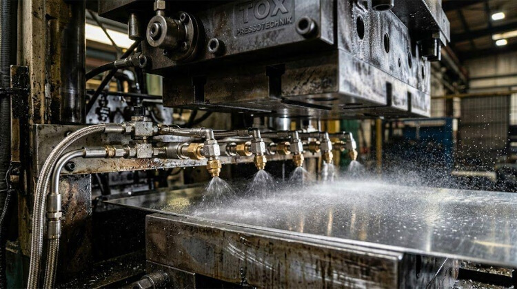
Lubrication Maintenance
- The Pain Point: Thermal breakdown of the friction barrier, leading to torn parts.
- The Root Cause: At 30 to 60 strokes per minute, tooling generates massive heat. Manual swabbing or outdated drip-lubrication systems cannot maintain consistent fluid coverage.
- The Solution: Integrate programmable, automated spray nozzles that deliver precise micro-doses of Extreme Pressure (EP) drawing compounds immediately before the die closes.
Surface Cleaning After Forming
- The Pain Point: High failure rates in downstream secondary operations, such as TIG welding defects or blotchy electropolishing results.
- The Root Cause: The highly viscous, heavy-duty oils required for deep drawing bake onto the metal from the heat of deformation. They cannot be wiped away manually.
- The Solution: High-volume production absolutely requires industrial multi-stage ultrasonic cleaning or vapor degreasing lines. If your stamping supplier lacks heavy-duty washing infrastructure, cleaning becomes a massive production bottleneck.
Dimensional Consistency & Springback
- The Pain Point: Flanges warp out of flatness, and total depth drifts out of tolerance.
- The Root Cause: Austenitic stainless steels exhibit significant springback. As tool clearances wear and press operating temperatures fluctuate during a long shift, the exact springback value changes dynamically.
- The Solution: Utilize Statistical Process Control (SPC). Operators must measure critical dimensions at set intervals to micro-adjust press parameters (like Blank Holder Force – BHF) before out-of-spec parts are mass-produced.
Combining Deep Drawing With Secondary Processes
A common DFM error in high-volume production is forcing a single progressive die to form every complex feature of a part. On the shop floor, deep drawing is most effective when treated as the high-speed foundation of a composite manufacturing architecture.
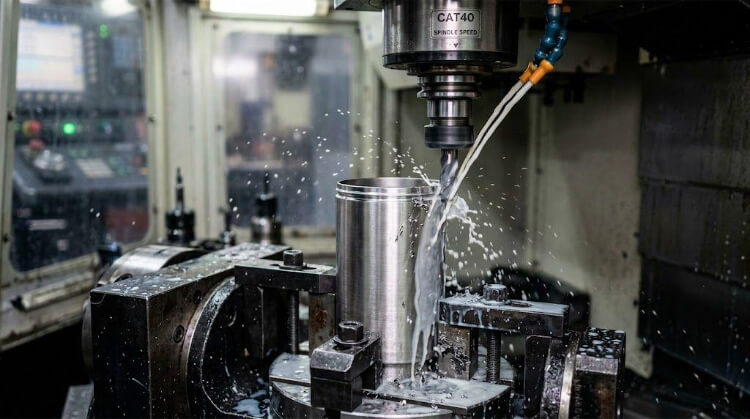
CNC Machining After Drawing
Deep drawing excels at volumetric shaping but inherently lacks micro-precision.
- The Engineering Rule: A standard draw die reliably holds general tolerances of ±0.15mm to ±0.25mm. If a component requires an O-ring groove, tapped threads, or a critical mating surface with a flatness tolerance of 0.02mm, it must be machined.
- The Manufacturing Strategy: Draw the blank shell first to establish the bulk geometry, then fixture the part in a 5-axis CNC mill. This hybrid approach captures the material utilization of stamping alongside the aerospace-grade tolerances of machining.
Laser Cutting for Complex Features
Designing a progressive die with side-action cams to pierce holes in the sidewall of a drawn cup is mechanically complex, expensive, and introduces significant maintenance liabilities.
- The Cost Impact: For production volumes under 50,000 units, the NRE (Non-Recurring Engineering) investment for complex side-piercing tooling is rarely justifiable.
- The Manufacturing Strategy: Utilize 3D/5-axis laser cutting cells. The press draws the solid shell, and the robotic laser rapidly cuts asymmetrical flanges, irregular side windows, or complex port layouts. This keeps the primary stamping die mechanically simple, robust, and less prone to downtime.
Welding and Assembly Operations
When a drawn part requires mounting brackets, internal standoffs, or integration into a larger assembly, welding is inevitable.
- The Engineering Rule: The high thermal expansion coefficient of stainless steel means thin-walled drawn parts will warp severely under unregulated heat input.
- The Manufacturing Strategy: Specify precision TIG or laser welding using strict fixturing jigs to control heat dissipation. Furthermore, if welding is in the process pipeline, specify 304L or 316L to prevent intergranular corrosion at the Heat-Affected Zones (HAZ).
Surface Finishing Realities
Procurement calculations frequently underestimate the cost of finishing drawn stainless parts. The extreme friction of the cold forming process leaves the surface visually dull and covered in micro-striations.
- The Cost Impact: Mechanical polishing (e.g., a #4 brushed finish) or electropolishing can easily add 20% to 30% to the final unit cost.
- The DFM Solution: If electropolishing or chemical passivation is required, the part geometry must eliminate deep crevices or folded hems. Unsealed gaps will trap acidic chemical baths, resulting in localized corrosion weeping weeks after the part enters service.
Process Comparison: When Deep Drawing Justifies the Tooling
Before committing to the high initial tooling cost of a deep draw die, it is necessary to justify the ROI. When evaluated against multi-piece welding or machining from solid billet, deep drawing offers distinct commercial and structural advantages for high-volume runs.
Process Comparison for High-Volume Stainless Steel Parts:
| Metric | Deep Drawing | CNC Machining | Welding / Fabrication |
| Ideal Volume | High (>10,000 units) | Low to Medium | Low to Medium |
| Material Waste | Low (~10-15%) | High (Up to 80%) | Medium |
| Production Speed | Very Fast (30-60 PPM) | Slow (10-30 mins/part) | Slow (Manual/Robotic) |
| Structural Integrity | Excellent (Seamless + Work Hardened) | Excellent (Solid Billet) | Variable (Heat Affected Zones) |
| Upfront Tooling Cost | High | Low | Low to Medium |
| Per-Unit Cost at Volume | Lowest | Highest | Medium |
Lower Part Count and Assembly Labor
- The Engineering Reality: Fabricating a cylindrical housing by rolling sheet metal and welding a separate end cap requires three distinct elements (wall, cap, weld filler) and multiple handling operations.
- The Commercial Advantage: Deep drawing forms that identical housing from a single blank in one continuous stroke. Eliminating weld seams radically reduces Bill of Materials (BOM) complexity, assembly labor, and the variable risk of operator error.
Enhanced Structural Strength
- The Engineering Reality: Weld seams are inherently the weakest points of any enclosure, susceptible to fatigue cracking and porosity.
- The Commercial Advantage: Deep-drawn parts are seamless. Additionally, the rapid work hardening that makes stainless steel difficult to form becomes a structural asset. The cold-worked sidewalls of a drawn 304 shell possess a significantly higher yield strength than the original annealed coil.
Faster High-Volume Production
- The Engineering Reality: Hollowing out a 100mm deep stainless steel cup on a CNC lathe might require 15 to 25 minutes of spindle time.
- The Commercial Advantage: A press can stamp that exact geometry at a rate of 30 to 60 parts per minute. The break-even ROI point—where production speed outpaces tooling amortization—is typically between 5,000 and 10,000 units. Beyond that volume, unit costs drop drastically.
Near-Net-Shape Material Utilization
- The Engineering Reality: CNC machining is subtractive. Machining a thin-walled enclosure from a solid 316 block turns up to 80% of the raw material into scrap chips.
- The Commercial Advantage: Deep drawing is a Near-Net-Shape process. Aside from the trimmed flange (typically kept below 15% of the blank area), the vast majority of the purchased coil stock remains in the final component.
Conclusion
Mastering stainless steel deep drawing is an exercise in balancing material science with manufacturing economics. To avoid the traps of fractured walls, destroyed tooling, and blown budgets, engineers must design strictly within the Limiting Drawing Ratio (LDR), specify the correct alloy grade, and understand the harsh realities of mass-production tool wear.
At TZR, our engineering team has more than 10 years of experience in sheet metal fabrication, CNC machining, and rapid prototyping. Upload your 3D CAD or STEP files today for a full DFM review. Our engineers will help you find practical ways to improve your part design and prepare it for efficient high-volume production.