
 English
  Spanish
  German
  Russian
  Italian
  French
Stainless steel machining is the process of cutting corrosion-resistant alloys like 304, 316, and 17-4 PH using CNC equipment. Due to its rapid work-hardening rate and low thermal conductivity, successful machining requires highly rigid setups, high-pressure coolant, and specialized carbide tooling to prevent rapid tool wear.
While stainless steel offers unmatched durability for end-use parts, it is notoriously unforgiving on the shop floor. The wrong cutting strategy or a mismatched material grade can quickly lead to dimensional errors and expensive scrap. A simple programming mistake or a micro-pause in feed rate can instantly work-harden a 316 stainless blank and destroy a $50 end mill in seconds.
To achieve tight tolerances without inflating production costs, engineers and buyers must align their part designs with manufacturing realities. This guide breaks down the exact material selections, tooling strategies, DFMA principles, and inspection requirements needed to scale your stainless steel parts from a single prototype to reliable volume production.
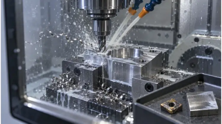
Why Stainless Steel Is Difficult to Machine?
Its incredible durability makes stainless steel a true nightmare on the shop floor. Understanding these core physical bottlenecks is the first step to preventing expensive, sudden tool failures.
Work Hardening Starts With Rubbing
When a cutting tool rubs against stainless steel instead of shearing it cleanly, the material surface undergoes rapid plastic deformation and hardens.
A common mistake among inexperienced operators is reducing the feed rate to “play it safe.” In stainless steel, this causes the tool edge to plow and rub, instantly hardening the surface. This hardened layer drastically increases the cutting force required for the next pass, which dulls the cutting edge faster and feeds back into more rubbing.
Low Feed or Dwell → Rubbing → Hardened Surface → Higher Cutting Force → Faster Tool Wear
Heat Stays Near the Cutting Edge
Unlike aluminum, which dissipates heat efficiently throughout the workpiece, stainless steel has low thermal conductivity. During machining, the heat generated by friction and shearing remains trapped at the cutting edge and within the chip.
This extreme localized temperature breaks down tool coatings and weakens the carbide substrate. While heat is a primary concern, built-up edge (BUE) is also driven by poor tool geometry, material adhesion, and inadequate lubrication. In extended machining cycles, this trapped heat causes thermal expansion and dimensional drift. Coolant must physically reach the exact cutting zone to stabilize the temperature and keep tight tolerances intact.
Long Chips Damage Tools and Surfaces
Austenitic grades like 304 and 316 are highly ductile, which means they produce continuous, stringy chips rather than breaking cleanly. These chips can easily wrap around the spindle, the tool, or the workpiece.
If chips are not properly evacuated, they are pulled back into the cutting zone. Recutting these hardened chips destroys the cutting edge and leaves random gouges on the machined surface. In deep-hole drilling or slotting, chip packing is the primary cause of sudden tool breakage. This forces operators to stop the machine frequently to clear chips, eliminating the possibility of cost-effective, lights-out (unattended) machining.
| Machining Issue | Common Causes | First Checks |
| Rapid tool wear | Rubbing, excess heat, or work hardening | Feed rate, tool edge condition, and dwells |
| Drag marks on surface | Built-up edge (BUE) | Edge sharpness, coolant position, and lubricity |
| Random surface scratches | Recutting evacuated chips | Chip evacuation path and coolant volume |
| Broken drills in deep holes | Chip packing or excessive torque | Through-tool coolant, feed rate, and peck cycles |
| Chatter marks | Lack of rigidity | Tool overhang, workholding, and cutting loads |
Choosing the Right Stainless Steel Grade
Not all stainless steel alloys behave identically under a cutting tool. Selecting the optimal grade requires balancing required mechanical performance against the harsh realities of machining costs.
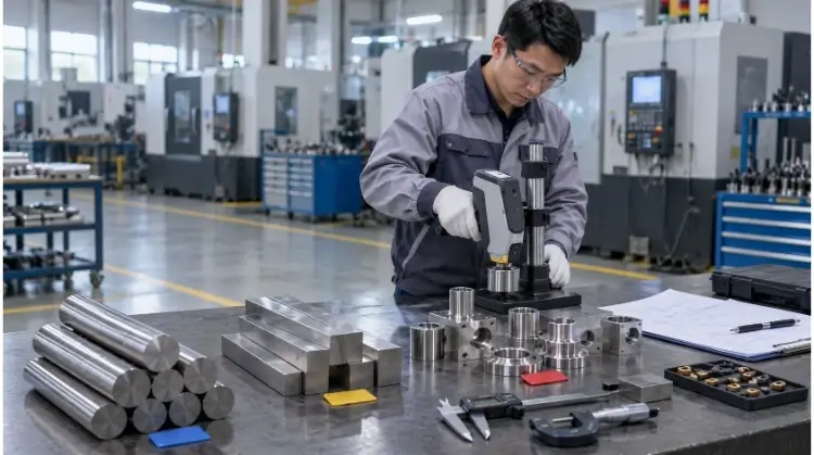
303 vs. 304 Stainless Steel
Grade 304 is the standard general-purpose austenitic stainless steel, offering good corrosion resistance and weldability. However, it is notorious for rapid work hardening and stringy chips.
Grade 303 contains added sulfur, which acts as an internal lubricant to break chips cleanly. Substituting 304 with 303 can reduce machining cycle times by 20% to 30%, significantly lowering the cost per part for high-volume turned components. The trade-off is that 303 has lower corrosion resistance and very poor weldability.
Grade 303 can drastically reduce machining costs, but it should only replace 304 if the end-use environment, welding requirements, and compliance standards permit it.
304 vs. 316 Stainless Steel
Both 304 and 316 share similar machining challenges: high work-hardening risks and long chips.
Grade 316 adds molybdenum, providing superior resistance to chlorides. This makes it the strict standard for marine, chemical, food processing, and medical environments. However, this added toughness accelerates tool wear and increases total machining time.
The choice between 304 and 316 is dictated entirely by the end-use environment. Once selected, the machine shop must optimize the cutting strategy to manage the higher costs associated with 316.
416, 17-4 PH, and Duplex Grades
Grade 416 is a highly machinable martensitic stainless steel that can be heat-treated for higher strength, though its corrosion resistance is limited compared to the 300 series.
17-4 PH (precipitation-hardening) is heavily utilized for aerospace and high-strength precision parts. Its machinability depends entirely on its heat-treated condition. Machining 17-4 PH often requires roughing in the annealed state, sending the part out for heat treatment, and then finish machining to manage dimensional distortion—a sequence that directly extends project lead times.
Duplex stainless steels, such as 2205, combine high strength with excellent corrosion resistance but generate extreme cutting forces. Machining Duplex requires exceptionally rigid setups, strict tool life monitoring, and aggressive chip control.
| Grade | Machinability | Corrosion Resistance | Strength | Primary Considerations |
| 303 | Good | Moderate | Moderate | Limited weldability and corrosion performance |
| 304 | Medium-Low | Good | Moderate | Prone to work hardening and long, stringy chips |
| 316 | Low | Excellent | Moderate | High heat generation and faster tool wear |
| 416 | Good | Low-Moderate | Heat treatable | Environmental applications are highly restricted |
| 17-4 PH | Varies by condition | Good | High | Heat treatment sequence affects dimensions and lead time |
| 2205 | Low | Excellent | High | Extreme cutting forces require maximum machine rigidity |
How to Control Heat, Chips, and Tool Wear?
Consistent machining requires strict control over cutting mechanics and thermal dynamics. A failure in chip evacuation or heat management guarantees scrapped parts and broken tools.
Milling and Turning Strategies
In milling operations, the primary goal is maintaining consistent tool engagement and avoiding sudden spikes in cutting force. Avoid full-slotting (180° radial engagement) whenever possible, as it traps heat and packs chips. Instead, use trochoidal milling or dynamic toolpaths to control radial engagement, maintaining a true chip thickness that effectively pulls heat away from the workpiece. Always keep tool overhang as short as possible to maximize rigidity, and use variable-helix or variable-pitch end mills to dampen harmful vibrations (chatter). Furthermore, roughing and finishing must be strictly separated; never expect a roughing end mill to deliver a precision finish on a work-hardened surface.
For turning, chip control dictates the process. Operators must use inserts featuring stainless-specific chip breakers to curl and snap the ductile chips of 300-series alloys. A continuous, aggressive feed rate is required to keep the insert under the work-hardened layer. When dealing with interrupted cuts, select a tougher carbide grade to prevent edge chipping. Always pause to verify insert wear before executing the final finishing pass to ensure tight tolerances are met.
For complex geometries, 5-axis CNC machining is often the most cost-effective approach. By reducing the number of setups from three or four down to just one, 5-axis machining minimizes stack-up errors and manual intervention, allowing the spindle to approach the part at optimal angles using shorter, more rigid tools.
Drilling and Threading Strategies
Deep hole drilling (where the depth-to-diameter ratio exceeds 4:1) is notoriously difficult in stainless steel. High-pressure, through-spindle coolant (typically 1,000 PSI / 70 bar or higher) is mandatory. External flood coolant simply deflects off the spinning drill and fails to reach the cutting zone, leading to instant heat buildup. Peck drilling cycles help break and evacuate chips, but programmers must avoid micro-retractions that cause the drill tip to rub and harden the bottom of the hole. Ensure the drill enters and exits on a flat, stable surface to prevent deflection.
Threading carries the highest risk of catastrophic failure. A broken tap stuck in a deep blind hole often results in a scrapped part. For deep or blind holes, thread milling is significantly safer than rigid tapping. While thread milling is slower, it requires less cutting force, allows for pitch diameter adjustments, and eliminates the risk of an unremovable broken tool.
In deep hole machining, failure rarely comes from a soft drill bit; it happens because coolant cannot reach the cutting tip and chips cannot evacuate smoothly.
Tools, Speeds, and Coolant
Standard High-Speed Steel (HSS) tools have no place in a modern production environment cutting stainless steel; solid carbide tooling is the baseline. Tools should feature a positive rake angle to shear the material rather than push it. For austenitic grades (like 304), a sharp cutting edge is ideal to prevent work hardening, while harder grades (like 17-4 PH) benefit from a slightly honed edge to prevent chipping. Advanced coatings, such as TiAlN or AlTiN, are essential as they form a protective aluminum oxide layer at extreme temperatures, shielding the carbide substrate.
Precision tool holders, such as shrink-fit or hydraulic chucks, are critical to minimize runout. Excessive runout means only one flute does the cutting, slashing tool life in half.
The exact cutting parameters depend entirely on the material condition, machine rigidity, tool geometry, and coolant application. The table below outlines conservative starting parameters designed to balance tool life with material removal rates.
| Process | Material | Tooling | Starting Surface Speed (SFM) | Starting Feed | Coolant Strategy |
| Milling | 304 | Solid Carbide End Mill (TiAlN) | 250 – 350 | 0.001 – 0.003 in/tooth | Flood or Through-spindle |
| Turning | 316 | Carbide Insert (Stainless Chip Breaker) | 200 – 300 | 0.006 – 0.012 in/rev | Targeted High-volume Flood |
| Drilling | 304 | Solid Carbide Drill (Internal Coolant) | 150 – 200 | 0.003 – 0.006 in/rev | Through-tool (1,000+ PSI) |
| Threading | 316 | Thread Mill / Premium Tap | 40 – 80 | Varies by pitch | High-lubricity Coolant |
How Part Design Affects Machining Accuracy and Finish?
High machining costs are often driven by poor part design rather than the material itself. Optimizing part geometry for manufacturability drastically reduces setup times and scrap rates.
Tool Access and Internal Features
Features that are trivial to design in CAD can be punishingly expensive to machine in stainless steel. Deep pockets, deep narrow slots, and sharp internal corners force machinists to use long, small-diameter end mills. These fragile tools must run at drastically reduced speeds to avoid deflection and breakage, multiplying the machining cycle time and labor cost. Other cost-drivers include cross-holes that create internal burrs, and tiny threads placed at the bottom of deep cavities.
Designers should aggressively apply Design for Manufacturing (DFM) principles:
- Increase non-functional internal corner radii to allow the use of larger, standard-sized end mills (e.g., 1/4″ or 6mm), rather than fragile micro-tooling.
- Standardize radii across the part to minimize unnecessary tool changes.
- Provide tool runout clearances for threading and grooving operations.
- Minimize the depth-to-diameter aspect ratio for all internal pockets and holes.
Original Design: A 2-inch deep pocket with sharp 90-degree internal corners.
DFM Revision: The same pocket with 0.25-inch internal corner radii and a floor relief groove. Result: Machining time reduced by 60%.
Thin Walls and Part Deformation
Machining induces stress, and stainless steel actively fights back. When a large volume of material is aggressively removed from a stainless steel blank, internal residual stresses are released, causing the part to warp or bow. Thin walls are especially vulnerable to deformation caused by the physical clamping force of the vise.
To combat distortion, machine shops separate roughing and finishing operations. Material must be removed symmetrically from both sides of the part to balance stress. Before the final finishing pass, operators often unclamp the part and lightly re-torque it in custom soft jaws to establish a true datum without inducing mechanical stress. Furthermore, critical dimensions must only be measured after the part has achieved thermal equilibrium. A hot stainless part will shrink out of tolerance as it cools.
Intermediate stress relief may be considered when material condition, stock removal, and final performance requirements justify it.
Tolerances, Surface Finish, and Deburring
A blanket block tolerance (e.g., applying ±0.001” to the entire drawing) is the fastest way to inflate the cost of a stainless steel part. Only apply tight tolerances to critical functional interfaces. Unnecessary tight tolerances force the machine shop to add finishing passes, slow down feed rates, and implement expensive in-process Coordinate Measuring Machine (CMM) inspections.
Demanding a low surface roughness (Ra) inside a deep bore or across a non-functional surface similarly drives up machine time. If a design requires both tight geometric tolerances and extreme surface finishes, the part may require secondary grinding or honing operations, significantly extending the lead time. Finally, specify exactly how edges should be treated; removing internal burrs in intersecting cross-holes requires specialized manual labor or expensive abrasive flow machining.
| Drawing Requirement | Production Impact | Cost Risk |
| Standard non-mating dimensions | Standard machining and spot-check inspection | Low |
| Localized tight tolerances | Requires finishing passes and in-process gauging | Moderate |
| Multiple connected GD&T features | Demands complex setups and full CMM reporting | High |
| Tight tolerances on thin walls | Highly susceptible to clamping and thermal distortion | Very High |
| Tight tolerance + Low Ra finish | Often requires secondary grinding or honing | Very High |
How to Reduce Stainless Steel Machining Costs?
Scaling from a single prototype to full production completely changes the cost equation. Strategic decisions in part design, batch sizing, and quality control dictate your final ROI.
What Drives Part Cost
To optimize budgets, buyers must understand exactly where the money goes. The basic formula is straightforward:
Part Cost = Material + Programming & Setup + Machining Time + Tooling + Finishing + Inspection + Scrap Risk
In prototyping, the upfront programming and setup time dominate the price. As volume increases, these fixed costs are distributed across the batch, and the financial focus shifts entirely to maximizing tool life and minimizing machine downtime. Features like deep holes, deep slots, and tight tolerances directly inflate machining time and tool depreciation.
A Real-World Cost Reduction Case:
- Original Design: A fluid manifold machined from a solid 316 stainless block, requiring four separate setups.
- The Problem: Deep intersecting holes caused frequent chip packing, leading to broken drills, excessive downtime, and high scrap rates.
- DFM Modification: Our engineers recommended switching to a near-net-shape cast blank to minimize total material removal. We also increased the internal hole diameters slightly to accommodate standard tooling.
- The Result: By moving the part to a 5-axis mill, setups were reduced from four to one. Machining time dropped by 45%, tool life increased by 300%, and the dimensional quality stabilized instantly.
Inspection and Surface Protection
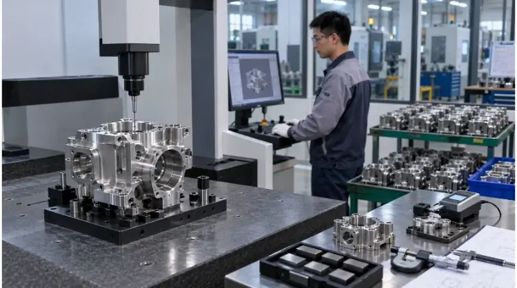
Quality control and surface finishing are not afterthoughts; they must be engineered into the production plan. Buyers should require their suppliers to provide Material Test Reports (MTRs), First Article Inspections (FAI), and CMM reporting to guarantee compliance.
When specifying surface treatments on stainless steel, pay close attention to these critical nuances:
- Passivation is not a coating. It is an acid treatment (usually nitric or citric) that removes free iron from the machined surface, allowing the natural, rust-proof chromium oxide layer to reform.
- Beware of cross-contamination. If your drawing calls for bead or sandblasting, the shop must use dedicated media. Blasting stainless with media previously used on carbon steel will embed iron particles into your part, causing it to rust rapidly in the field.
- Electropolishing removes material. This process dissolves microscopic surface peaks to create a mirror-like finish, typically removing 0.0005″ to 0.001″ of material. This removal must be factored into the pre-finishing machining tolerances. If tight-tolerance bores or threads cannot afford this material loss, expensive manual masking will be required before surface treatment.
- Specify grain direction. If requesting a brushed finish, always indicate the required grain direction on your 2D drawing for aesthetic consistency.
Production Readiness
Before awarding a volume contract, verify that your manufacturing partner is truly equipped for stainless steel production. A reliable supplier should answer “yes” to these questions:
- Do they have documented experience with your specific grade and heat-treat condition?
- Do their machines utilize high-pressure, through-spindle coolant for chip evacuation?
- Do they track tool life trends to prevent dimensional drift across a long production run?
- Can they manage thin-wall distortion and perform in-house stress relief if necessary?
- Do they offer a comprehensive DFM review before cutting the first chip?
To get the most accurate and fastest quote, ensure your RFQ package includes:
- 2D drawing (with critical GD&T clearly marked)
- 3D CAD model (STEP or IGES)
- Exact material grade and required condition (e.g., 17-4 PH H900)
- Order quantity and Estimated Annual Usage (EAU)
- Specific surface roughness (Ra) and secondary treatments (e.g., Passivation per ASTM A967)
- Required inspection documents (MTRs, FAI, CMM reports)
- A brief description of the end-use environment
Conclusion
Reliable stainless steel machining depends on more than selecting a carbide tool. Material grade, part geometry, cutting strategy, coolant, tolerances, and inspection requirements must work together seamlessly from the first prototype to full production.
Ready to optimize your next project? Send us your 2D drawing, 3D model, stainless steel grade, quantity, and critical tolerances. Our engineers will review the part for machining risks, manufacturability, and possible cost reductions before quotation.
FAQs
Is stainless steel difficult to machine?
Yes, primarily due to its rapid work-hardening rate and low thermal conductivity. Instead of shearing cleanly, it often rubs against the tool, hardening the surface and trapping heat at the cutting edge. This leads to accelerated tool wear and chip control issues, requiring rigid setups and optimized carbide tooling.
Which stainless steel grade is easiest to machine?
Grades 303 and 416 are generally the easiest to machine. They contain added sulfur, which acts as an internal lubricant to break chips cleanly. This allows for significantly faster cutting speeds and extended tool life, making them ideal for high-volume machining where extreme corrosion resistance is not strictly required.
Is 303 a suitable replacement for 304?
It depends entirely on the end-use environment and assembly methods. Grade 303 machines up to 30% faster than 304, drastically reducing production costs. However, the added sulfur lowers its corrosion resistance and makes it highly unsuitable for welding. Only substitute 303 if the application permits it.
Is 304 or 316 easier to machine?
Grade 304 is slightly easier to machine than 316. The addition of molybdenum in 316 improves its resistance to harsh chlorides (like marine or medical environments) but makes the alloy physically tougher. This increased toughness generates more heat and accelerates tool wear, requiring slower feeds and rigid machining strategies.
How can work hardening be reduced?
Work hardening is prevented by maintaining a continuous, aggressive feed rate. The cutting tool must stay constantly engaged beneath the hardened surface layer. Never allow the tool to dwell or rub against the workpiece. Using sharp, high-quality carbide tools and high-pressure coolant also minimizes the friction that triggers the hardening process.