
 English
  Spanish
  German
  Russian
  Italian
  French
To properly sand stainless steel, start with a 36 to 60-grit abrasive for weld removal or deep scratches. Progress sequentially through 120, 240, and 400-grit to refine the surface. Always sand parallel to the grain and strictly use iron-free (INOX) abrasives to prevent corrosion.
Sanding stainless steel is not just about aesthetics; it is a critical mechanical process that dictates the part’s fatigue strength, corrosion resistance, and manufacturing cost. Choosing the correct starting abrasive and knowing exactly when to stop depends on the initial surface condition, the type of defect, and the target appearance.
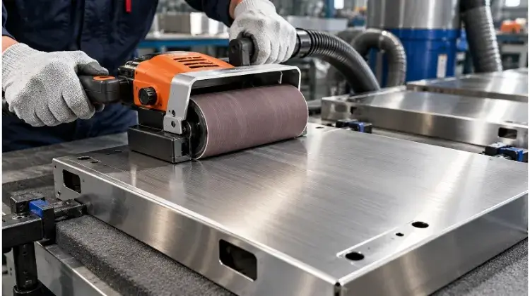
Brushed vs. Polished Stainless Steel: Which Finish Fits?
Before selecting an abrasive, it is necessary to assess the current state of the metal and define the exact limits of the operation.
Existing Finish
Verify the current surface condition of the stainless steel. It may be a raw mill finish (like 2B), a mechanical finish (like No. 4 brushed), or it may have an anti-fingerprint clear coat applied.
If a clear coat or specialized surface treatment is present, sanding will strip it, resulting in a highly visible patch. Based on this, determine if the process requires a localized scratch repair or if the entire visible face must be resurfaced to maintain uniformity.
Damage and Thickness
Differentiate between surface stains, shallow scuffs, deep gouges, and weld seams. You must also evaluate the material grade (e.g., 304 versus the harder 400 series), plate thickness, and dimensional tolerances.
Removing a deep scratch inherently means removing base metal. Before attempting to sand out a deep gouge, confirm against the engineering drawing that the required material removal will not compromise the part’s thickness tolerance.
Target Finish
Define the end goal using measurable parameters. Clarify whether the part requires a directional grain, a uniform satin appearance, or a highly reflective mirror polish.
Relying solely on a grit number (e.g., “finish to 400 grit”) often leads to misaligned expectations between fabrication and quality control. Instead, specify the required surface roughness (e.g., Ra ≤ 0.8 µm for food-grade applications) and use approved physical reference samples to establish the visual standard.
How to Choose Sandpaper Grit for Stainless Steel?
Selecting the correct abrasive sequence ensures efficient material removal while preventing unnecessary rework and surface damage.
Starting Grit
The starting grit is dictated by the deepest defect on the workpiece. Always test the abrasive sequence on a small, inconspicuous area or a scrap piece first. For leveling TIG welds or removing heavy scale, starting with 36 or 60 grit is typical, while 120 or 240 grit is often sufficient for light surface scratches.
Starting with an abrasive that is too coarse creates unnecessarily deep gouges that require more time and steps to remove later. Conversely, starting with an abrasive that is too fine will cause the pad to glide over the defect, generating excess heat without effectively cutting the metal.
Abrasive Selection
Abrasives perform differently on hard alloys like stainless steel. The selection depends on the specific machining task:
- Ceramic Alumina: Handles heat well and retains sharp cutting edges, making it suitable for heavy stock removal and weld blending.
- Silicon Carbide: Cuts cleanly and leaves a highly consistent scratch pattern, which works well for fine blending and preparing surfaces for final polishing.
- Aluminum Oxide: A standard option for general deburring, though it tends to dull faster on stainless steel compared to ceramic options.
Warning: Crucially, all abrasives used must be iron-free (often marked as INOX). Using a grinding disc, belt, or hand pad previously used on carbon steel will embed free iron into the stainless surface, causing rapid galvanic corrosion and rust spots.
Tool Matching
Match the mechanical tool to the part geometry and the target finish. Flat surfaces usually require random orbital sanders or wide belt sanders to distribute pressure and avoid creating low spots. Curved surfaces, inside corners, and tight geometries rely on die grinders, rotary tools, or manual hand blocks.
The backing pad also influences the cut: a hard backing pad keeps edges flat and aggressive, while a soft interface pad conforms to curves and softens the scratch pattern. When operating mechanical tools, RPM must be matched to the abrasive manufacturer’s specifications to prevent heat distortion.
| Processing Task | Abrasive Format | Selection Basis | Limitations & Notes |
| Heavy weld removal | Ceramic flap disc / Fiber disc | High cut rate and structural heat resistance. | Leaves deep scratches; requires stepping down through multiple finer grits. |
| Flat surface blending | Hook & loop paper discs | Consistent cut and easy changeover. | Edge gouging may occur if the tool is tilted or the backing pad is undersized. |
| Final brushed finish | Non-woven abrasive drum / Hand pad | Conforms to surface variations, leaves linear grain. | Does not remove base material or deep scratches; only conditions the surface layer. |
How to Sand Stainless Steel Step by Step?
Execution dictates the final quality just as much as abrasive selection. Following a structured sequence ensures consistent material removal and helps operators identify when it is safe to transition to a finer grit.
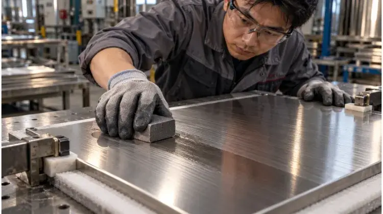
Clean and Inspect
Always start by degreasing the stainless steel surface. Wipe the surface with a chloride-free solvent (such as acetone or isopropyl alcohol) to prevent stress corrosion cracking.
Any residual cutting fluid, oil, or shop dust left on the metal will immediately load up the abrasive pad. Sanding over dirt drags hard particles across the metal, creating new, unpredictable scratches.
Secure the Part
Clamp or fixture the workpiece securely before applying any mechanical tool. Stainless steel requires consistent contact pressure to cut effectively.
If the part vibrates, the tool will bounce and leave distinct chatter marks. For thin sheet metal, ensure there is adequate backing support—such as a flat sacrificial board—to prevent the material from flexing under the sander.
Test Starting Grit
Apply the chosen starting grit to a small, hidden section of the part. Run the tool for a few seconds, wipe the area clean, and inspect the scratch pattern.
The abrasive should cut the metal efficiently without requiring excessive downward force. If you must push hard to remove the defect, step down to a coarser grit. If the abrasive immediately creates a deep trench, move to a finer grit.
Sand in Passes
Keep the tool moving in smooth, overlapping passes. Never let a powered sander idle in one spot, as this quickly generates localized heat and hollows out the surface.
Let the abrasive do the cutting. Heavy manual pressure generates friction rather than shear force, leading to rapid abrasive wear and thermal distortion in the metal.
Refine and Inspect
Stop and clean the part entirely before switching to a finer grit. Verify that all deep scratches from the previous stage have been completely replaced by the uniform scratch pattern of the current grit.
Jumping to a finer abrasive too early only polishes the peaks of deep scratches. This creates a surface that looks shiny but still contains visible gouges under certain lighting.
How to Remove Scratches Without Changing the Finish?
Matching an existing finish requires adjusting the tool motion and knowing exactly when to stop. Different visual targets demand completely different operational approaches.
Brushed Finish
When repairing a brushed surface, all tool motion must strictly follow the existing grain direction, typically using a linear burnishing tool or non-woven conditioning belts. Crossing the grain instantly destroys the linear pattern.
On highly visible components like commercial refrigerator doors, localized repairs often stand out as a noticeable patch. If blending fails, it is usually more cost-effective to re-grain the entire face from edge to edge to guarantee visual uniformity.
Satin Finish
A true satin finish relies on a uniform, non-directional micro-scratch pattern. Do not treat a specific grit number (like “400 grit”) as the sole indicator of a finished part, as abrasive wear alters the actual visual output.
Instead, compare the workpiece against an approved physical sample under standard shop lighting. Focus on checking the overall uniformity and ensuring the light reflects evenly across the part without obvious bright or dull patches.
Mirror Finish
Sanding does not create a mirror finish; it only establishes the baseline for the buffing process. The goal of the final sanding stages (typically up to 1000 or 2000 grit) is to eliminate all directional scratches.
Before moving to cotton wheels and compounds, inspect the surface closely. Buffing will not remove residual sanding marks or “pigtails”—it will only make them highly reflective and more noticeable.
Why Stainless Steel Looks Uneven After Sanding?
When the final appearance fails inspection, operators must systematically trace the visual defect back to the mechanical process.
Scratches and Swirls
Distinguish between leftover coarse scratches and newly generated ones. If isolated, deep scratches remain after fine sanding, the operator likely skipped a grit level or moved on too quickly.
If the surface contains random “pigtail” swirls, the cause is often a loaded abrasive pad or foreign debris trapped under the disc. This is common when using random orbital sanders at excessive feed rates.
Uneven Patches
Visible bright spots, dark zones, or overlapping patch marks usually stem from inconsistent tool contact. Tilting an angle grinder or applying uneven pressure to a hand block changes the cut depth.
Using a worn-out abrasive belt on one half of a panel and a fresh belt on the other will also cause distinct light reflection differences. Depending on the severity, the operator must decide whether to attempt a localized blend or expand the sanding scope to unify the whole area.
Heat and Distortion
Stainless steel retains heat. Blue or yellow discoloration (heat tint) indicates that the metal has reached a temperature where the surface begins to oxidize. On thin sheet metal, localized overheating causes the metal to warp or “oil-can.”
While heat tint can sometimes be chemically removed, severe oil-canning permanently destroys the dimensional tolerance, resulting in a scrapped part. When heat tint appears, stop immediately, let the part air cool, and replace the dull abrasive.
Defect Troubleshooting Matrix
Use the following checks to determine the next operational step when defects appear:
| Visible Defect | Priority Checks | Next Action |
| Deep scratches remain after fine sanding | Were previous grit marks fully removed? Is there new debris on the pad? | Continue current grit, drop back a grit level, or replace loaded abrasive. |
| Uneven bright/dark patches | Check tool contact angle, operator pressure, and abrasive wear state. | Attempt localized blend or expand the graining scope across the full surface. |
| Heat tint or part warping | Check tool dwell time, part fixturing support, and abrasive cutting efficiency. | Pause operation, assess dimensional stability, and install fresh abrasives. |
When Stainless Steel Needs Passivation After Sanding?
Mechanical sanding physically strips away the stainless steel’s protective chromium oxide layer. A part that looks shiny and flawless is not necessarily protected against corrosion.
Residue Removal
Sanding leaves behind microscopic metal swarf, shed abrasive grit, and exhausted coolant sludge. Before any chemical treatment or downstream assembly begins, the part must be thoroughly cleaned.
Use industrial degreasers to remove organic residues. If wet sanding was employed, ensure the metal-laden slurry is cleaned from all blind holes and safely disposed of according to facility environmental protocols, rather than left to dry on the workpiece.
Iron Contamination
If rust spots appear on freshly sanded stainless steel, do not immediately assume the material is defective or experiencing pitting corrosion. The most common cause is free iron contamination.
Trace the operational workflow to find the source. Contamination occurs when operators use wire brushes, abrasives, or fixtures previously exposed to carbon steel. It also happens when parts are dragged across contaminated steel workbenches or handled with unprotected forklift tines.
Further Treatment
A visually acceptable surface does not guarantee field performance. You must differentiate between general cleaning, heat tint removal, and chemical passivation. Pickling acids dissolve heavy oxidation and weld scale, while passivation chemically restores the corrosion-resistant passive layer.
Whether passivation (such as ASTM A967 nitric or citric acid treatments) is strictly required depends on the end-use environment and client specifications. Parts destined for medical, food-grade, or marine environments always require documented chemical passivation after mechanical finishing.
Skipping passivation to save fabrication costs often leads to catastrophic field failures, warranty claims, and rejected assemblies months after delivery.
How to Specify Stainless Steel Finishes and Avoid Rework?
Misaligned expectations between engineering, purchasing, and the fabrication floor are the primary cause of cosmetic rework. Vague drawing notes like “polish smooth” or “brushed finish” leave too much room for interpretation.
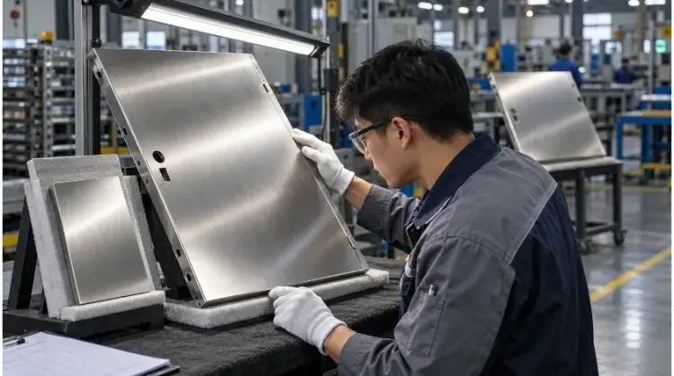
Appearance Samples
Define the aesthetic requirements clearly. Specify which surfaces are the primary visible faces (A-sides) and which are hidden (B-sides). If a directional grain is required, indicate the exact axis of the grain on the engineering drawing.
For assemblies like equipment enclosures, matching adjacent parts is critical. A cabinet door and its side panel must reflect light identically. Use physical master boundary samples signed off by both the buyer and the manufacturer to establish the acceptable visual baseline.
Measurement Requirements
Visual acceptance and dimensional compliance are two separate approvals. Always verify critical dimensions, edge radii, and plate flatness after sanding, as material removal can push thin parts out of tolerance.
If a surface roughness limit is specified on the drawing, explicitly define the measurement location and direction. For brushed finishes, measuring the Ra value perpendicular to the grain will yield a significantly higher reading than measuring parallel to it.
Cost Drivers
Surface finishing is highly labor-intensive. The initial material condition, defect severity, surface area, and part geometry all drive the cycle time. While flat panels can be processed quickly on automated wide-belt sanders, complex welded assemblies require manual blending, exponentially increasing labor hours.
Engineers can actively reduce this cost through Design for Manufacturability (DFM)—such as moving weld seams away from visible inside corners to allow for automated machine blending rather than manual hand-finishing.
The target finish drastically impacts the procurement budget. Upgrading a welded assembly from a standard No. 4 brushed finish to a No. 8 mirror polish often multiplies the finishing cost by three to five times due to the strict grit sequence required. Finally, mandate that finished parts be wrapped in protective laser film immediately after inspection to prevent transit damage.
Ready to move your project into production?
Accurate finishing starts with clear documentation. Send us your 3D STEP files and 2D PDF prints with critical visible faces and GD&T callouts clearly marked. We will review your geometry and material specifications to provide a precise manufacturing quote and establish the optimal abrasive process for your application.