
 English
  Spanish
  German
  Russian
  Italian
  French
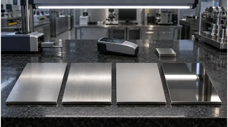
A satin metal finish is a smooth, low-gloss surface created through controlled abrasive machining. Its microscopic texture diffuses light to reduce glare and hide minor fingerprints and scratches. Unlike a bright mirror polish, it provides a uniform, muted sheen ideal for visible cosmetic components.
Typing “Satin Finish” on an engineering drawing is not a verifiable manufacturing specification. Because this finish is produced mechanically, the final aesthetic is heavily distorted by the base material, weld locations, sheet thickness, and the abrasive grain direction. Without strict documentation, you risk receiving parts with mismatched grain across assemblies, rounded functional edges, and severe thermal warping on thin panels.
This guide breaks down exactly what a satin finish means on the factory floor. We will cover the specific DFM (Design for Manufacturability) rules, surface roughness (Ra) limits, and the exact drawing notes you need to specify to prevent costly supplier disputes and field rejections.
What a Satin Metal Finish Actually Means?
Specifying a surface finish requires a clear understanding of what the term covers on the factory floor. Satin describes a broad aesthetic category rather than a strict technical standard or a single machining method.
Surface Texture and Light Reflection
A satin surface relies on microscopic abrasions that scatter light. Because it is not tied to a single standardized process, there is no universal Ra (roughness average) value that defines a satin surface.
However, a typical industrial satin finish usually falls between Ra 0.4µm and 1.2µm (16–48 µin). Specifying a tighter Ra than necessary within this range will exponentially increase finishing costs without significantly altering the visual appearance. Furthermore, the perceived gloss and visual weight of the grain will shift depending on lighting conditions. When evaluating surface consistency, it is standard practice to compare physical samples of the exact same material, under identical lighting, and from the same observation angle.
Directional and Non-Directional Grain
The chosen abrasive method dictates whether the final texture has a visible linear pattern.
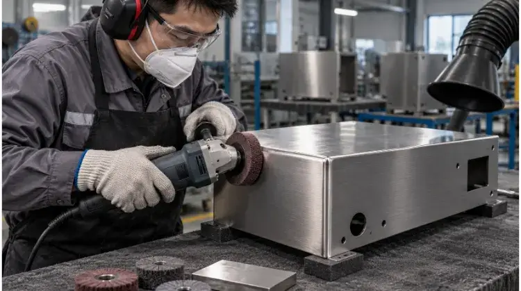
- Directional grain is typically achieved using wide abrasive belts, non-woven abrasive wheels (such as Scotch-Brite), or linear brushing equipment. This creates distinct, parallel lines along the part. It is standard for large flat panels but requires precise alignment during CAD nesting and assembly so the grain matches across mating components.
- Non-directional grain results from random orbital sanding or fine media blasting. It yields a uniform, frosted appearance without a linear track.
In production, non-directional finishes are generally easier to match across complex welded assemblies. They are also more forgiving if local touch-ups are required, as there is no existing linear pattern that a technician might cross-scratch during a localized repair.
Satin Vs. Other Metal Finishes
To determine if satin is the correct specification for a component, engineers must baseline it against other common mechanical finishes, evaluating both performance and manufacturing risk.
| Finish Type | Light Reflection | Grain Direction | Scratch Tolerance | Repairability | Cost Impact / DFM Risk |
| Satin | Medium (diffused) | Directional or Non-directional | Good | Moderate | Moderate: Scales well with automated wide-belt sanding. |
| Brushed | Medium (linear) | Strictly Directional | Excellent (along grain) | Difficult (requires blending) | Moderate to High: Requires precise manual blending on welds. |
| Matte | Very Low | Non-directional | Poor (shows oils) | Easy | Low: Easily achieved via tumbling or heavy blasting. |
| Mirror | Very High | None (polished flat) | Very Poor | Very Difficult | Very High: Extremely labor-intensive and rejects are common. |
| Bead-Blasted | Low (frosted) | Non-directional | Poor | Requires re-blasting | Low to Moderate: Highly repeatable but requires dedicated blasting cabinets. |
Satin works well for high-contact visible surfaces—such as control panels, architectural hardware, and enclosures—where glare reduction and moderate scratch tolerance are necessary. It is not recommended for high-friction mechanical sliding components or environments where heavy particulates can become trapped in the abrasive micro-texture.
How Process and Material Change the Finish?
The final appearance of the metal is dictated by the interaction between the abrasive equipment and the physical properties of the base material.
Abrasive Methods and Process Order
Generating a consistent finish requires selecting the right equipment for the part geometry. Common factory methods include wide-belt sanding for flat sheet metal, narrow-belt grinding for edges, non-woven wheels for contour blending, manual abrasive pads for touch-ups, and automated brushing machines for high-volume runs.
The standard process sequence for a fabricated sheet metal part is usually:
Cutting → forming → welding → weld blending → satin finishing → cleaning or passivation → inspection → packaging.
Variations exist based on supply chain decisions. Purchasing pre-brushed sheet metal lowers finishing time and costs, but it requires protective film during press brake bending and limits the factory’s ability to hide subsequent welds without creating a visible “halo” effect where the local grinding meets the factory grain.
Stainless Steel, Aluminum, and Soft Metals
The base metal directly impacts how the abrasive process behaves and what quality control precautions are strictly necessary.
- Stainless Steel: It takes a directional grain extremely well. The initial mill finish of the sheet (e.g., 2B) will influence the depth of the final texture. Cross-contamination is a primary risk on the shop floor; dedicated abrasives must be used. Using a shared grinding wheel will cause rapid surface rusting (rouge) on a 304 or 316 stainless part as soon as it is exposed to humidity, leading to immediate field rejections. Also, note that the standard “No. 4 finish” is a specific directional stainless specification and does not cover all satin variations.
- Aluminum: Aluminum is softer than steel and dissipates heat differently. Running thin panels (e.g., 1.2mm or 1.5mm sheet metal) under a wide abrasive belt with too much pressure can induce thermal warping, destroying the part’s flatness. Furthermore, if the aluminum part requires post-process anodizing, the satin finish must be exceptionally uniform. The anodizing process does not hide scratches; it magnifies underlying abrasive inconsistencies.
- Copper and Brass: These soft metals mark and dent easily during mechanical processing. Their surface color changes naturally through rapid oxidation. A satin finish on copper or brass usually requires a secondary clear protective coating (such as a clear lacquer) immediately after finishing to lock in the appearance and prevent tarnishing during transit.
Material Removal and Dimensional Risk
Mechanical satin finishing inherently removes material. This reduction must be accounted for in the engineering tolerances, especially for precision components.
Heavy abrasive processing can alter sheet thickness and degrade overall flatness on large spans. It can also inadvertently round off sharp edges or alter small internal fillets. Critical features—such as tapped holes, countersinks, precision mating surfaces, and laser-engraved markings—are at risk of deformation if subjected to heavy finishing passes. Functional surfaces and tight-tolerance profiles should be masked or explicitly excluded from abrasive processing on the drawing unless material removal rates have been calculated and approved.
How Part Design Affects Finish Consistency?
Applying a satin finish is not just a surface treatment; it is a mechanical process strictly constrained by the geometry of the part. Designing for Manufacturability (DFM) at the sheet metal stage prevents visual defects that are virtually impossible to correct during final finishing.
Welds and Heat-Affected Areas
Achieving a uniform grain texture across a welded joint presents significant metallurgical and geometric challenges. The weld area rarely matches the base metal seamlessly for several practical reasons:
- Hardness variations: Weld filler material often cures at a different hardness than the base sheet metal. When an abrasive belt passes over the joint, it removes material at different rates, altering the depth of the grain.
- Geometric distortion: Grinding a weld perfectly flush alters local flatness. If the technician over-grinds even slightly, it creates a shallow undercut or “halo” that catches light differently than the surrounding flat panel.
- Heat-Affected Zones (HAZ): The intense heat of welding alters the micro-structure of the surrounding metal. Even after the surface is leveled and grained, a subtle color band or shadow may remain visible under certain lighting conditions.
- Grain interruption: Cross-directional marks from aggressive angle-grinding during weld leveling are notoriously difficult to fully erase with fine satin abrasives.
Engineers must clearly dictate whether a weld strictly needs to be ground flush. The requirement should be a calculated balance between structural integrity, sheet thickness, and the designated cosmetic grade of the enclosure.
Bends, Corners, and Large Panels
A flat metal coupon with a perfect satin finish looks vastly different when formed into a 3D component.
- Visual shifts at bends: A press brake bend permanently alters how light reflects off the metal. Even if the grain is perfectly uniform, the formed radius will scatter light differently, making the finish appear slightly darker or lighter at the bend line.
- Tooling clearance constraints: Small internal corners restrict the entry of abrasive wheels and hand pads. It is physically impossible to achieve the exact same linear grain inside a tight 90-degree corner as on a wide-open exterior face.
- Edge rounding: Sharp external edges are highly susceptible to becoming radiused (rounded) under the pressure of abrasive belts.
- Deep cavities: Narrow slots and deep pockets restrict access for standard finishing media, often resulting in patchy textures.
- Large panel amplification: Broad, flat surfaces (such as a server rack door) act like mirrors for defects. They amplify minute variations in gloss, abrasive wear, and belt pressure. On a large panel, local rework to fix a single 2cm scratch is glaringly obvious; the shop cannot simply buff out the scratch. The entire face usually requires complete re-graining to maintain consistency, essentially doubling the labor cost for that component.
Grain Direction Across Assemblies
For products built from multiple sheet metal or CNC components, the grain direction must be deliberately coordinated across the entire assembly to prevent a patchwork appearance. Common control strategies include:
- Unified direction: All parts are grained to align uniformly when the product is fully assembled (e.g., all grain runs vertically on a machine cabinet).
- Long-edge alignment: The grain on every individual part runs parallel to its longest dimension.
- Primary viewing angle: Grain is oriented based on how the end-user will interact with the product.
Without strict documentation on the 2D drawing, a major conflict arises between aesthetics and material efficiency. To maximize material yield (nesting efficiency), CAD programmers will routinely rotate flat patterns on sheet metal blanks. If grain direction is not locked by the engineer, parts will be laser-cut at 90-degree offsets. Once assembled, the conflicting grain directions will reflect light in opposing ways, ruining the cosmetic intent.
How to Specify Satin Finish on Drawings?
Ambiguous drawing notes cause more manufacturing delays and supplier disputes than actual machining errors. A note stating only “Satin Finish” is not a verifiable engineering specification.
Visible Surfaces and Finish Zones
Technical drawings must explicitly demarcate finish requirements using a tiered zone system:
- Material and state: Specify the exact alloy and starting mill finish (e.g., 304 Stainless Steel, 2B finish).
- A-Side (Primary Visible): Faces with zero tolerance for visual defects, requiring strict grain consistency.
- B-Side (Secondary Visible): Areas where minor tooling marks or slight grain deviations are acceptable.
- Hidden Surfaces: Internal faces that do not require cosmetic finishing.
- No-Grind Zones: Functional mating surfaces, tight-tolerance cutouts, or hardware insertion points where abrasive material removal is strictly prohibited.
- Edge and weld requirements: State clearly if welds are to be left as-welded, ground flush, or blended.
For complex components, do not rely on text notes like “grain along length.” Use distinct vector arrows on the CAD drawing to dictate the exact linear path of the grain for each face.
Grit, Roughness, and Gloss
Engineers often confuse the metrics used to measure surface properties.
- Grit: Indicates the abrasive particle size (e.g., 120-grit, 320-grit) or the process tool.
- Ra/Rz: Measures the microscopic peaks and valleys (roughness) of the surface using a profilometer.
- Gloss units (GU): Measures the amount of light reflected at a specific angle (usually 60°).
- Grain direction: Dictates the visual linear alignment.
- Reference sample: The physical baseline for final visual acceptance.
When writing technical documentation, the following rule must be understood:
Grit, roughness, and gloss describe different surface properties. None of them alone fully defines the appearance of a directional satin finish.
Citing a “No. 4 finish” or a specific Ra value provides a helpful processing baseline for the factory, but it cannot serve as the sole universal standard for satin acceptance, as two surfaces with identical Ra values can look entirely different under factory lighting.
Golden Samples and Acceptance Limits
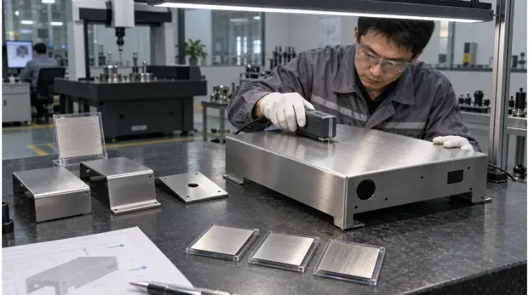
Because technical documents cannot fully quantify light diffusion and visual texture, physical samples are mandatory for high-cosmetic parts.
- Golden Sample: The perfect target representing the ideal surface finish, approved by the client.
- Boundary Samples: Physical pieces demonstrating the upper and lower limits of acceptability (e.g., maximum allowable scratch depth, lightest acceptable grain).
- First Article Inspection (FAI): The first production unit run using the exact production materials, tooling, and abrasive media to verify the process matches the Golden Sample.
The QA Reality Check: Physical metal samples degrade over time due to natural oxidation, factory dust, and handling. A common QA failure is relying on a two-year-old sample for a new batch. Golden samples should be stored in VCI (Volatile Corrosion Inhibitor) bags and formally renewed every 12 to 18 months.
To prevent disputes, physical samples must be permanently labeled with the material batch, grain direction, abrasive used, measured Ra/Gloss, sample ID, and the signed approval date.
How to Prevent Satin Finish Defects
A visually flawless satin finish is easily ruined by inconsistent shop floor practices or poor handling after the machining is complete. Preventing defects requires strict process control, from the abrasive belt to the final shipping crate.
Uneven Grain and Local Repair
Surface defects usually stem from manual inconsistencies or cross-contamination during the finishing stage.
| Defect | Common Cause | Control Method |
| Uneven grain depth | Variation in applied pressure or feed rate. | Standardize automated machine parameters; limit manual fatigue. |
| Transverse scratches | Incorrect final abrasive pass direction. | Lock single-direction finishing path across all operations. |
| Dwell marks | Abrasive tool lingering on one spot. | Maintain continuous, fluid movement during manual blending. |
| Weld shadow / Halo | Differential hardness or uneven local flatness. | Optimize TIG parameters; avoid over-grinding the weld root. |
| Bright spots | Rework area too localized. | Expand blending zone or re-grain the entire face. |
| Rounded edges | Excessive material removal at corners. | Limit abrasive pressure and pass count on sharp geometry. |
| Iron contamination | Shared abrasives with carbon steel parts. | Strictly segregate stainless steel finishing tools and media. |
First-Article and Batch Inspection
Visual acceptance cannot be left to a quick glance on the loading dock. A rigid inspection protocol prevents massive batch rejections.
Recommended Inspection Sequence:
- Manufacture the First Article Inspection (FAI) unit using production-grade materials and final abrasive media.
- Verify the grain direction against the 2D engineering drawing.
- Measure the stipulated Ra (Roughness) or Gloss Units to ensure the process falls within the calculated baseline.
- Compare the FAI unit side-by-side with the approved Golden Sample under standardized conditions.
- Lock the abrasive parameters and approve the FAI before releasing the full batch for production.
- Conduct periodic random sampling throughout the batch run to detect abrasive wear (which causes the grain to slowly become shallower and shinier).
Defining the Inspection Environment: To avoid subjective arguments, the inspection criteria must be documented. A standard factory QA agreement dictates: “Surfaces shall be inspected under D65 daylight bulbs, viewed at a distance of 18–24 inches (45–60 cm), at a 45-degree viewing angle, for a maximum of 5 seconds per face.” If a defect is invisible under these conditions, it passes.
Cleaning, Handling, and Packaging
More satin parts are scrapped due to poor post-processing handling than actual machining errors. The microscopic grooves of a satin finish easily trap oils and debris. Finished surfaces can be destroyed by:
- Bare hand contact: Acidic oils from fingerprints can etch soft metals and leave dark smudges.
- Part-on-part friction: Stacking finished plates without interleaving paper causes immediate galling.
- Incorrect solvents: Harsh chemical cleaners can strip protective oxides or leave a cloudy residue.
- Assembly tool strikes: Slipping screwdrivers or wrenches during final assembly create deep gouges.
- Adhesive residue: Protective laser films left on the metal for too long, or baked in heat, leave stubborn glue tracks.
- Transit vibration: Parts vibrating against cardboard or strapping bands during shipping will polish the contact points, creating bright rub marks.
The Cost of Bad Packaging: Skipping a $0.50 piece of interleaving paper can instantly scrap a $500 finished panel during a 10-hour transit. Never compromise on custom packaging for A-Side cosmetic parts. Parts with A-Side requirements demand cleanroom-style handling (nitrile gloves) and should be individually bagged and separated by non-abrasive foam.
How Satin Finish Affects Cost and Sourcing
Procurement managers often underestimate the cost of finishing. Surface treatment is highly labor-intensive, and the price scales exponentially with geometric complexity and quality expectations.
Automated Vs. Manual Finishing
The single biggest cost driver is the ratio of automated machine time to manual labor.
- Automated Finishing: Flat panels, simple enclosures, and extrusions can be fed through wide-belt sanders or automated brushing lines. This process is fast, highly repeatable, and cost-effective.
- Manual Finishing: Complex welded frames, deep chassis, and irregular shapes cannot fit through a flat-belt machine. They require technicians to use pneumatic drum sanders, hand-held burnishing machines, and non-woven abrasive pads.
The higher the manual intervention, the higher the risk of batch-to-batch variation and rework. A factory cannot simply “angle-grind” its way to a premium satin finish. Manual blending requires highly skilled labor, which drastically increases the unit price.
Geometry and Quality Requirements
Do not assume cost is strictly tied to part size. A small 150mm complex welded bracket will often cost significantly more to satin finish than a 1000mm flat sheet.
Primary cost multipliers include:
- Total number of visible faces (A-Sides).
- Quantity and length of welds requiring flush blending.
- Internal corners and deep cavities that slow down tool access.
- Strict Ra measurement or 100% visual inspection requirements.
- Custom packaging and individual boxing.
- Low order volumes (finishing setups are time-consuming).
Supplier Capability and RFQ Checklist
Not all sheet metal or CNC shops are equipped to deliver consistent cosmetic finishes. When auditing a supplier, verify the following capabilities:
- Do they have wide-belt equipment sized for your largest flat panels?
- Do they have a dedicated, physically segregated area for stainless steel processing to prevent iron contamination?
- Do they own calibrated profilometers to measure Ra?
- Do they have a formal system for storing and managing Golden Samples (e.g., VCI bagging)?
- Do their standard operating procedures mandate protective film and interleaving paper during internal shop routing?
🚩 Red Flag: If a supplier tells you they can “easily blend all welds with a standard angle grinder” without mentioning grain distortion or halo effects, look for a new manufacturing partner.
Conclusion
A satin metal finish is not a fixed, universal standard you can pull from a drop-down menu. It is a highly engineered aesthetic outcome driven by material selection, starting surface conditions, abrasive methods, grain orientation, and the physical geometry of the part.
For high-visibility components, engineers must lock down finish zones and grain directions explicitly on the drawing. Procurement managers must then close the loop by establishing physical boundary samples and First Article Inspections.
Not sure if your current drawing notes are leading to overpriced quotes? Send your 2D and 3D files to the engineering team at TZR. We’ll provide a free, honest DFM review and a precise manufacturing quote within 24 hours.