
 English
  Spanish
  German
  Russian
  Italian
  French
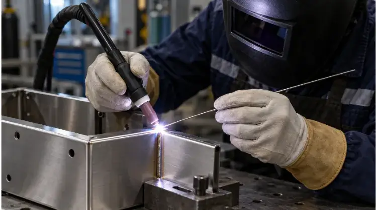
Common TIG welding mistakes include inadequate surface cleaning, incorrect tungsten grinding, excessive shielding gas flow, and poor heat control. These errors cause porosity, arc wandering, and severe part distortion. Fixing them requires strict joint preparation, optimizing gas coverage, and balancing amperage with travel speed.
TIG welding is incredibly unforgiving. A single misstep in preparation or arc control doesn’t just make a weld look ugly—it ruins expensive parts, causes NDT (Non-Destructive Testing) failures, and drives up hidden rework costs that destroy profit margins.
Troubleshooting TIG defects requires looking past surface-level symptoms. In the following sections, we isolate the root causes of the most critical manual welding failures—such as cold lap and thermal distortion—and provide the exact process adjustments required to correct them.
| Field Symptom | First Check | Reference Section |
| Porosity or contamination in the weld | Base metal, filler rod, gas shielding | Pre-Weld Preparation & Gas Coverage |
| Arc wandering or unstable starts | Tungsten, equipment settings, connections | Arc Stability |
| Burn-through on thin sheets or part distortion | Joint gap, heat buildup, weld sequence | Heat Control & Distortion |
| Excessive bead buildup or poor fusion | Puddle control, arc placement, filler feeding | Fusion & Execution |
| Craters left at the end of the weld | Crater filling and slope-down | Fusion & Execution |
| Final dimensions or function fail specs | Inspection criteria, actual part condition | Quality Checks |
Note: This table provides a troubleshooting starting point. Visual symptoms alone may not confirm the root cause.
Welding Before the Metal and Joint Are Ready
Rushing the setup phase is the fastest way to ruin expensive parts. Proper preparation prevents hidden defects and keeps your production cycle running smoothly.
Surface Cleaning
TIG welding cannot burn through surface contaminants. Leaving oil, moisture, mill scale, or zinc coatings on the base metal guarantees porosity and weak joints, often remaining hidden until final X-ray or leak testing and causing expensive late-stage scrap. Cleaning must be material-specific. Aluminum requires a dedicated stainless steel wire brush to break the heavy oxide layer, followed by a solvent wipe like acetone. Carbon steel typically requires grinding or sanding to remove mill scale before welding.
The filler rod is another common source of contamination. Always wipe down bare filler rods before use and store them in sealed tubes; a dusty or oxidized rod will introduce impurities directly into the puddle.
Joint Fit-Up
Inconsistent fit-up forces the welder to manually compensate for varying gaps, increasing cycle times and making repeatable results impossible across a batch. Wide gaps in thin sheet butt joints quickly lead to burn-through, while mismatched edges (hi-lo) in corner joints for enclosures make it difficult to maintain a consistent arc length. Furthermore, if the joint design does not allow the TIG torch cup enough clearance, the operator cannot maintain the proper torch angle or gas coverage. Parts must be tacked securely with uniform gap tolerances before production welding begins.
Filler Selection
Choosing the wrong filler metal alters the mechanical properties and cracking resistance of the final part. In a production environment, filler selection goes beyond simply matching the base metal name—it must align with the specific alloy grade and post-weld processing requirements. For example, selecting 4043 over 5356 filler for an aluminum enclosure will result in a stark color mismatch if the part is later anodized.
Wire diameter must also match the joint volume. A wire that is too thick chills the puddle and causes poor fusion, while a wire that is too thin melts prematurely, failing to fill the joint and slowing down the overall welding cycle.
Why More Gas Does Not Mean Better Shielding?
Cranking up the argon pressure is rarely the right fix for weld oxidation. Effective gas coverage relies on stable, controlled flow rather than sheer volume.
Gas Flow and Leaks
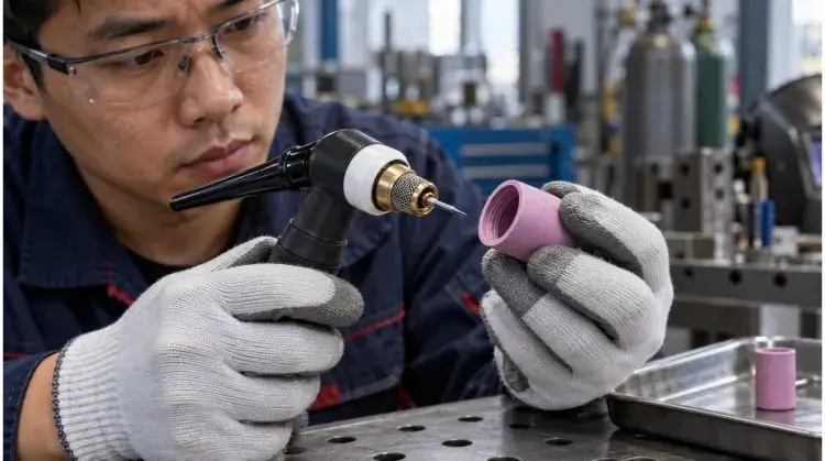
A common misconception is that increasing argon flow fixes oxidation issues. In reality, excessive gas flow creates turbulence, physically pulling atmospheric oxygen and nitrogen into the weld pool. A standard flow rate for a #8 cup is typically 15 to 20 CFH (Cubic Feet per Hour) in a draft-free environment, but this must be adjusted based on cup size and joint geometry.
Before turning up the flow meter, check the entire delivery system. A loose fitting, damaged O-ring, or cracked hose draws air into the gas line. This not only contaminates the weld but also silently drives up argon costs over a production run.
Coverage and Drafts
The reading on the flow meter does not guarantee actual gas coverage at the joint. A steep torch angle or excessive tungsten stick-out pushes the shielding gas away from the puddle. Upgrading to a gas lens helps create a laminar flow, allowing a slightly longer tungsten extension for better visibility without sacrificing gas coverage.
Environmental factors also disrupt the gas shield. Shop fans, open bay doors, or heavy exhaust vents easily blow the shielding gas away. In drafty shop conditions, use physical windbreaks around the workstation rather than simply cranking up the gas flow.
Back Purging and Post-Flow
Shielding is required until the metal cools below its critical oxidation temperature, both on the front and the back of the weld. Post-flow protects the tungsten and the weld crater after the arc stops. The operator must hold the torch stationary over the end of the weld until the post-flow timer finishes to prevent crater defects.
Back purging protects the reverse side of the joint. For stainless steel, oxygen exposure on the backside causes “sugaring”—heavy, granular oxidation that destroys corrosion resistance and mechanical strength. Back purging the root with argon is non-negotiable for sanitary tubing or full-penetration stainless welds.
(Note: Heat discoloration on the face of the weld is related to heat input and travel speed, which will be covered in later sections).
Why Your TIG Arc Wanders or Becomes Unstable?
An erratic arc makes precision welding impossible and slows down cycle times. Stabilizing your setup ensures the heat goes exactly where the joint needs it.
Tungsten Selection and Grinding
Mismatched tungsten parameters directly cause arc wander. For DC welding on steel or stainless, standard 2% ceriated or lanthanated tungsten works well. For AC welding on aluminum, a truncated (slightly flattened) tip helps form a stable ball.
However, the most common shop-floor error is the grinding direction. Always grind parallel to the length of the tungsten. Radial (wrap-around) grinding marks act like microscopic threads, causing the arc to deflect and wander erratically. In precision joints, this misdirected heat causes uneven root penetration, leading to immediate failures in ultrasonic or X-ray inspections.
Tungsten Contamination
Dipping the tungsten into the puddle or touching the filler rod instantly contaminates the electrode, splitting or extinguishing the arc. While regrinding the tungsten is mandatory after a dip, repeated trips to the bench grinder kill production efficiency and disrupt the operator’s rhythm.
To stop the cycle, investigate the root cause rather than just treating the symptom. Check your arc length—maintaining a tight arc without proper hand or arm support inevitably leads to dipping. Additionally, verify that your filler wire feeding path approaches the leading edge of the puddle, not the electrode tip.
Polarity and Equipment Checks
Unstable arcs often stem from incorrect polarity settings or degraded ground connections. Always ensure the machine is set to DC Electrode Negative (DCEN) for carbon and stainless steel, and AC for aluminum.
If the polarity is correct, inspect the ground circuit. A loose or oxidized work lead (ground clamp) increases electrical resistance. This results in stuttering arc starts or an arc that continuously fades in and out during operation.
Aluminum AC Balance Tip: AC balance controls the cleaning action (EP) versus penetration (EN). If the arc wanders excessively and the tungsten balls up too much, the EP setting is likely too high. Adjust for more EN to tighten the arc, increase penetration, and reduce tungsten degradation.
How to Prevent Burn-Through and Weld Distortion?
Uncontrolled heat input warps critical dimensions and destroys thin-gauge parts. Managing thermal dynamics requires a careful balance of current, speed, and welding sequence.
Current and Travel Speed
Operators instinctively lower the amperage when facing burn-through on thin parts, but this is often the exact wrong fix. A current that is too low forces the welder to move slowly, dumping excessive overall heat into the part and causing severe, unrecoverable distortion.
The true engineering goal is to use higher amperage to establish a puddle instantly, allowing for a much faster travel speed. This “hot and fast” technique minimizes the heat-affected zone (HAZ), prevents warping, and significantly reduces the cycle time per part. When adjusting, watch the puddle width—it should remain consistent without ballooning as you move down the joint.
Heat Buildup
Continuous welding on long joints accumulates heat, causing the material to expand and buckle. For sustained operations, letting the part cool between passes is the simplest way to prevent thermal overload.
Pulsed TIG is another effective regulation tool; it alternates between peak and background currents to maintain joint penetration while significantly dropping the average heat input. However, pulse settings must be synchronized with manual travel speed. If the operator’s movement doesn’t match the pulse frequency, it creates a visually inconsistent, weak “dotted” weld bead.
Tack Welds and Sequence
Relying solely on physical clamps will not stop thermal distortion once those clamps are removed. Proper tack welding locks the joint geometry in place, while a planned welding sequence—such as skip welding or back-stepping—distributes the heat load evenly across the assembly.
The true test of your heat control happens after releasing the clamps. You must verify flatness, angular distortion, and overall assembly fit-up against the engineering drawing tolerances to ensure the part remains viable for the next manufacturing step.
Material Tip: For stainless steel, heat tint indicates the level of surface oxidation and thermal load. While a light straw or gold color is acceptable, a dark blue or heavily gray/black weld suggests excessive heat input. This means the metal has permanently lost its chromium layer and corrosion resistance. You cannot simply brush or pickle this away—the structural integrity of the part is already compromised.
How to Avoid Poor Fusion and Crater Defects?
A weld that looks fine on the surface can still fail under load. Proper fusion and controlled finishing ensure the joint remains structurally sound throughout its lifespan.
Arc Placement and Visibility
Poor fusion often starts with bad ergonomics. If the operator cannot clearly see the leading edge of the puddle, the arc will inevitably wander off the center of the joint. Poor ergonomics don’t just cause occasional defects. They cause physical operator fatigue that typically leads to a massive spike in scrap rates toward the end of a shift.
Arc placement also changes drastically depending on the joint type. For a T-joint, the arc must be driven deep into the root, rather than biased toward one sidewall. In a lap joint, the arc should focus slightly more on the bottom plate to prevent melting away the top edge before fusion occurs.
Puddle and Filler Control
Dumping excessive filler metal into a cold joint creates a buildup that simply sits on top of the base metal. Filler wire must be dabbed rhythmically into the leading edge of the puddle, allowing the arc heat to wash the molten metal smoothly into the weld toes.
It is critical to distinguish between Lack of Fusion (LOF) and Lack of Penetration (LOP). LOF (often called “cold lap”) is a silent killer in manufacturing. It routinely passes visual inspection because the surface bead looks perfect, only to fail catastrophically in the field under load.
Because surface photos cannot substitute for internal quality checks, visual inspection is not enough. A simple cross-section macrograph is the best way to verify if your puddle control is actually working.
Crater Filling and Restarts
Stopping the arc abruptly leaves a concave depression at the end of the weld known as a crater. Because this area cools and shrinks faster than the surrounding metal, it creates a massive stress riser that immediately generates “star cracks.”
To prevent this, use your pedal or torch switch to trigger a current slope-down. This tapers the heat while adding one final dab of filler to leave a strong, convex finish. If you need to restart a weld, always use a wire brush to clean the stop point and strike the arc slightly ahead of the crater before washing back into it.
Crack Troubleshooting Tip: While unfilled craters are a leading cause of cracking, they are just one factor. If a crack propagates down the center of the bead, you must also check for high joint restraint, incorrect filler wire selection, or rapid cooling caused by a cold shop environment.
How to Check Welds and Prevent Repeat Mistakes?
Catching defects early stops scrapped parts from moving downstream. A systematic inspection process guarantees that your corrective actions actually fix the root cause.
Surface and Root Checks
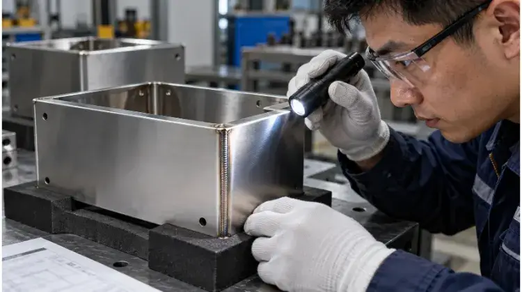
Visual Testing (VT) is the crucial first step. Operators must check the weld surface for porosity, undercut at the toes, and ensure the start/stop points are fully tied in. If the backside of the joint is accessible, inspect the root for complete penetration and signs of heavy oxidation.
However, visual checks have strict limits. A smooth surface bead can easily hide internal cold lap or subsurface porosity. If the part is structurally critical or holds pressure, you must rely on Non-Destructive Testing (NDT) such as dye penetrant, X-ray, or ultrasonic testing to verify true internal integrity.
Dimensions and Function
A structurally perfect weld is commercially useless if it warps the part out of specification. After the assembly cools and clamps are removed, verify the overall dimensions, angular tolerances, and flatness against the engineering drawings.
Functionality checks depend entirely on the part’s end-use. For instance, a fluid reservoir must undergo a pressure or leak test, while an electronics enclosure must be checked for proper lid fitment. Never mandate a blanket set of tests for every part; align the inspection criteria strictly with the actual project requirements to control costs.
First-Part and Rework Records
Dialing in a TIG process requires strict documentation. Record the baseline settings on the first-off part, note any defect locations, and change only one variable at a time (e.g., lower the heat OR change the travel speed). Changing multiple variables simultaneously makes it impossible to know which fix actually worked.
Preventing repeat mistakes directly protects your profit margins. Reworking a defective TIG weld often costs three to five times more than welding it right the first time. The hidden costs of grinding out a bad weld, re-fixturing the part, re-welding, and performing a second QA inspection will instantly wipe out the profitability of a production batch.
Purchasing Strategy Tip: Vague RFQs lead to inconsistent supplier quality. When requesting quotes, always provide the material grade, material thickness, joint drawings, and specific cosmetic/NDT requirements. This forces the supplier to accurately calculate their WPS (Welding Procedure Specification) and guarantees you receive parts that meet your exact standards.
Poor fit-up and inaccessible joints drive up manufacturing costs. Let TZR’s engineering team review your drawings for manufacturability (DFM) before the first arc is struck. We catch the blind spots early so you get stronger, cleaner, and more cost-effective parts.