
 English
  Spanish
  German
  Russian
  Italian
  French
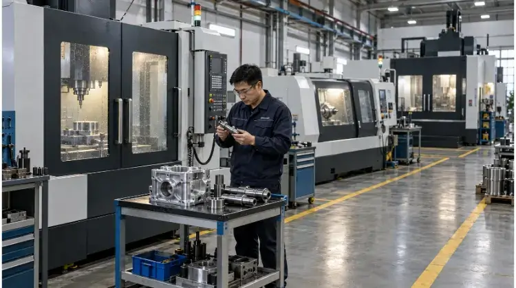
The most common types of CNC machines include CNC mills for prismatic and multi-faced parts, CNC lathes for cylindrical shapes, CNC routers for large flat panels, and EDM machines for hardened metals. Choosing the right machine depends on your part’s specific geometry and tolerances.
CNC machining isn’t a single process—it’s an umbrella term for a variety of subtractive technologies. While they all rely on programmed toolpaths, the distinction between these machines comes down to how the cutting tool moves, the structural rigidity of the equipment, and the number of programmable axes.
Understanding these mechanical differences is the practical first step in matching your CAD file to the right manufacturing floor. Below is a quick reference guide filtering the main types of CNC machines based on geometry and application:
| Machine Type | Typical Parts | Main Strength | Main Limitation |
| CNC Milling | Brackets, enclosures, flat plates | Versatile for prismatic and multi-face shapes | Multiple setups needed for multi-face parts |
| CNC Turning | Shafts, pins, threaded fittings | High speed and accuracy for symmetrical parts | Limited primarily to cylindrical geometries |
| CNC Routers | Large panels, plastic sheets | Cost-effective for large, flat work areas | Lower rigidity; not suitable for hard metals |
| EDM | Hardened tool steel, deep cavities | Cuts conductive metals without mechanical stress | Very slow processing speed |
CNC Milling Machines for Pockets and Multi-Face Parts
When a part features flat surfaces, drilled holes, internal pockets, or multi-sided geometries, CNC milling is the required process. In milling, the workpiece is clamped rigidly while a rotating cutting tool removes material.
Vertical Machining Centers (VMCs)
In a VMC, the spindle operates vertically, plunging down into the workpiece. This layout is the industry workhorse for parts mounted on flat plates, custom enclosures, and single-sided aluminum or steel brackets. Because the tool approaches from the top, operators have clear visibility for clamping the material directly to the table or inside a standard vise.
- DFM Focus: Internal corners must have a radius, as rotating tools cannot cut perfect 90-degree internal angles. Pay strict attention to cavity depth. As a general rule, when a pocket depth exceeds 3x to 4x the tool diameter, tool deflection becomes a significant risk, leading to chatter marks and reduced surface quality.
Horizontal Machining Centers (HMCs)
An HMC features a spindle mounted horizontally. This orientation allows gravity to pull metal chips away from the cutting zone, reducing tool wear and preventing the cutter from recutting chips. HMCs are usually equipped with rotary tables (“tombstones”) and automated pallet changers, allowing operators to load parts onto one pallet while the machine is actively cutting on another.
- Procurement Focus: Do not just compare hourly rates. While an HMC charges a higher hourly rate than a VMC, the ability to swap pallets in seconds often makes it the cheaper option for production runs over 500 units, as the total setup time per part drops drastically.
Gantry Milling Machines
Gantry mills use a bridge-like structure to support the spindle over a massive worktable. This design provides the structural stability required for heavy and oversized workpieces, such as large mold bases, aerospace bulkheads, and heavy equipment structural frames.
- Constraint: A large worktable does not guarantee easy access to all features. Machining deep features in the center of a massive plate may still require specialized extended tool holders to reach the intended surfaces without the bulky spindle housing colliding with the workpiece.
| Machine Layout | Typical Workpieces | Setup Approach | Main Constraint |
| Vertical (VMC) | Flat plates, brackets, shallow cavities | Simple vise or direct table clamping | Chip clearing in deep pockets, single-side access |
| Horizontal (HMC) | Multi-sided parts, heavy blocks | Tombstone fixtures, automated pallets | Higher initial tooling and fixture costs |
| Gantry Mill | Large molds, structural frames | Heavy-duty clamping, overhead crane loading | Large footprint, high capital equipment cost |
CNC Lathes for Round and Slender Parts
If your part involves shafts, bushings, threaded connectors, or any features that are symmetric around a central axis, it belongs on a lathe. In turning operations, the workpiece rotates at high speeds while a stationary cutting tool feeds into it to shape the profile.
CNC Turning Centers
Standard CNC turning centers hold the material in a chuck and turn the outer diameter (OD), bore the inner diameter (ID), cut grooves, face the ends, and machine threads. The process is highly efficient for round parts and removes material much faster than a milling machine interpolating a circle.
- DFM Focus: Ensure your design accounts for workholding. Long parts will require a tailstock for support against cutting pressure. Always establish clear datum surfaces on your drawing to maintain strict concentricity between internal bores and external diameters.
Swiss-Type Lathes
Swiss-type lathes differ from standard turning centers by utilizing a guide bushing. The raw bar stock feeds through this bushing, and the cutting tool operates immediately adjacent to it. This provides extreme rigidity exactly where the cut happens, preventing the material from bending.
- Application & Constraints: This is not just a “more precise lathe.” It is a specific architecture built for parts with a Length-to-Diameter (L/D) ratio exceeding 3:1 or 4:1 (e.g., slender aerospace fasteners, medical pins). Because the guide bushing requires tight clearances, the raw material must be high-quality, centerless-ground bar stock. Due to setup complexity, Swiss machining is usually justified only for high-volume batches (typically 1,000+ units).
Mill-Turn Centers
Mill-turn centers are advanced CNC lathes equipped with “live tooling” (rotating milling cutters) and programmable C or Y axes. This configuration allows the machine to turn the main cylindrical body, lock the rotation, and then mill flats, drill cross-holes, or cut off-center features without removing the part.
- Short Case Study: Consider a hydraulic manifold fitting with a threaded OD and a perpendicular cross-hole. If machined separately, the part is turned on a lathe, unloaded, moved to a VMC, clamped, and indicated to find the exact center for the hole. Every manual transfer introduces alignment errors. A mill-turn center performs both operations in a single setup. This reduces total handling time and eliminates the scrap risk caused by re-fixturing misalignment, guaranteeing the true position of the hole relative to the thread.
CNC Routers and Dedicated Holemaking Machines
While machining centers are highly versatile, certain geometries—like massive flat sheets or components dominated by repeating holes—require dedicated equipment configurations to be processed efficiently and economically.
CNC Routers
CNC routers are designed primarily for machining large panels of wood, plastics (like POM and Acrylic), composites, and occasionally soft metals. Unlike a VMC that uses a heavy cast-iron frame to ensure rigidity, a router uses a large gantry system spanning a wide work envelope.
- DFM & Tolerance Focus: Because routers operate with extremely high spindle speeds but lower structural rigidity, they typically hold tolerances around ±0.1 mm to ±0.2 mm, whereas a standard VMC comfortably holds ±0.01 mm. Do not route tight-tolerance aerospace aluminum. Additionally, sheet fixation relies on vacuum tables. If your parts have a small surface area, the vacuum will not provide enough holding force, requiring custom tabs in the CAD file that must be manually removed later.
CNC Drilling and Tapping Machines (Drill-Tap Centers)
A standard VMC can drill and tap holes, but a dedicated drill-tap center is built specifically for aggressive acceleration and deceleration. These machines feature lightweight spindles (typically BT30 or BBT30 tapers) and rapid tool change times (often under one second).
- Procurement Focus: If you are sourcing parts like aluminum heatsinks or telecom housings where 80% of the features are threaded holes, a drill-tap center will process the batch significantly faster than a standard mill. When dealing with deep hole drilling (e.g., L/D > 10:1), you must verify if the supplier has Through-Spindle Coolant (TSC) or dedicated gundrilling equipment to evacuate chips and prevent drill breakage.
CNC Grinding and EDM for Specialized Requirements
When a part’s requirements for dimensional accuracy, surface finish, or material hardness exceed the capabilities of standard cutting tools, manufacturers turn to grinding and Electrical Discharge Machining (EDM).
CNC Grinding Machines
Grinding uses an abrasive wheel to remove material in microscopic increments. Depending on the geometry, shops use surface grinders (for flat plates), cylindrical grinders (for OD/ID of shafts), or centerless grinders (for high-volume pins).
- DFM Focus: Grinding is typically a post-heat-treatment process used to hit tight tolerances (often ±0.002 mm or better) and superior surface finishes (Ra 0.4 or lower). You must leave a machining allowance on your drawing for the grinder to remove—usually between 0.1 mm and 0.3 mm. Additionally, design relief grooves (undercuts) at the base of shoulders so the grinding wheel has space to clear the cut.
Wire EDM Machines
Wire EDM uses an electrically charged brass or zinc wire to cut through conductive materials by eroding them with sparks. It exerts zero mechanical cutting force on the workpiece, making it ideal for delicate structures or fully hardened tool steels.
- DFM Focus: Wire EDM is used for precision through-profiles, extrusion dies, and narrow slots. However, to cut an enclosed internal profile, the operator must first drill a starter hole to thread the wire through. Furthermore, true sharp internal corners are physically impossible; the internal radius is dictated by the wire. A standard 0.25 mm wire will leave a minimum internal radius of approximately 0.15 mm (including the spark gap).
Sinker EDM Machines
Instead of a wire, Sinker EDM uses a custom-machined electrode (usually copper or graphite) to plunge into the workpiece, burning a blind cavity that matches the electrode’s exact inverse shape.
- Procurement Note: The electrode degrades during the burn. Complex cavities often require machining multiple electrodes (a “rougher” and a “finisher”), which significantly increases the upfront NRE (Non-Recurring Engineering) tooling costs.
- Short Case Study: When manufacturing a steel injection mold, sharp internal corners and deep, narrow ribs are required. A VMC is used first to rapidly rough out the bulk material, but the endmill inevitably leaves rounded corners. A graphite electrode is then machined with the exact sharp features, and the Sinker EDM burns away the remaining material. This hybrid routing balances the high material removal rate of milling with the geometric precision of EDM.
CNC Cutting and Bending Machines for Sheet Metal
Sheet metal fabrication relies on a completely different set of CNC equipment to cut flat profiles from raw sheets and form them into 3D brackets, panels, and enclosures.
CNC Laser Cutters
Laser cutters use a focused beam of light and an assist gas (like Nitrogen or Oxygen) to melt and blow away material. They are the standard for profiling flat sheet metal blanks for enclosures and chassis.
- DFM Focus: As a general rule, the diameter of a cut hole should not be less than the thickness of the material (a 1:1 ratio) to prevent the laser from blowing out the surrounding metal. Be aware that laser cutting creates a Heat-Affected Zone (HAZ) along the cut edge, which hardens the material and can cause taps to snap during secondary threading operations.
CNC Plasma Cutters
Plasma cutters use a jet of ionized gas to slice through conductive metals. While they generally yield a rougher edge and a wider kerf than a laser, they are significantly faster and more cost-effective for cutting thick mild steel plates (e.g., >10 mm) where edge precision is not the primary concern.
CNC Waterjet Cutters
Waterjets force highly pressurized water mixed with abrasive garnet through a small nozzle. The primary value of a waterjet is that it is a cold-cutting process; it introduces zero heat into the part. This is critical for aerospace alloys, thick titanium, or metals that warp easily under thermal stress.
- DFM Focus: Waterjet cuts naturally exhibit edge taper (a slight V-shape through the thickness of the cut). If the edge acts as a precision mating surface, you will need to add a secondary milling operation to square it up.
CNC Punching Machines
Punch presses use mechanical force to stamp standard tool shapes through sheet metal. Unlike lasers, punching machines can also create shallow 3D forms, such as louvers, dimples, and extruded countersinks, directly on the flat sheet.
- DFM Focus: Punching relies on a standard tooling inventory. Designing a custom hole shape will require a custom punch die, adding lead time and tooling costs. To prevent the sheet from deforming, maintain a minimum distance from the edge of the hole to the edge of the part—usually 1.5x the material thickness.
CNC Press Brakes
Once the flat pattern is cut, a CNC press brake uses a top punch and a bottom V-die to bend the sheet into its final 3D shape.
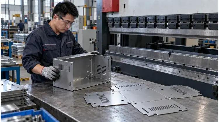
- DFM Focus: Standardize your bend radii so the operator doesn’t have to stop and change the heavy tooling multiple times. Keep holes away from the bend line, or they will distort during forming. Most importantly, respect the minimum flange length. A sheet cannot be bent if the lip is too short to safely bridge the V-die opening.
- Short Case Study: A server chassis starts as a flat sheet. It is laser-cut (profiling), moved to a press brake (bending), and finally, PEM nuts are pressed into the holes. The initial flat pattern CAD must account for the material’s specific “K-factor“—the exact amount the metal stretches during bending—so that the final folded flanges hit the required dimensional tolerances.
| Process | Suitable Features | Edge or Forming Considerations | Likely Secondary Operations |
| Laser Cutting | Intricate flat profiles, panels | Heat-Affected Zone (HAZ) hardens edges | Bending, hardware insertion (PEMs) |
| Waterjet Cutting | Thick plates, heat-sensitive metals | Creates edge taper; cold process | Edge milling for squareness |
| Punching | Louvers, high-volume repeated holes | Fast, but leaves minor tool witness marks | Deburring, bending |
| Press Brake | 3D flanges, brackets, enclosures | Material springback and stretch (K-factor) | Welding, powder coating |
Three-Axis, Four-Axis, and Five-Axis CNC Compared
The number of axes on a CNC machine dictates how many directions the cutting tool or the workpiece can move simultaneously. Upgrading from 3-axis to multi-axis is rarely about cutting the metal faster; it is about reducing the number of times an operator has to touch the part.
Three-Axis Machining
A 3-axis machine moves the tool along the X, Y, and Z planes. It easily handles flat surfaces, drilled holes, and pockets on a single face. If your part has features on the back or the sides, the machine must stop. The operator unclamps the part, rotates it, indicates it to find the new zero point, and clamps it again.
- Process Constraint: Every manual re-fixturing introduces “datum shift” or tolerance stack-up. If a hole on Side A must be perfectly concentric with a counterbore on Side B, relying on an operator to manually flip the part exactly to within ±0.01 mm introduces significant manufacturing risk.
Four-Axis Machining
A 4-axis machine adds a rotation axis (usually the A-axis, rotating around the X-axis). This is frequently accomplished by adding a rotary table to a standard VMC.
- Positional vs. Continuous: In indexing (or 3+1) machining, the 4th axis rotates the part to a specific angle, locks rigidly in place, and the 3-axis tool does its work. In continuous 4-axis machining, the part rotates simultaneously while the tool cuts, which is required for features like cam profiles or wrapping a toolpath around a cylinder.
Five-Axis Machining
A 5-axis machine adds two rotational axes, allowing the tool to approach the workpiece from almost any angle.
- 3+2 Machining (Positional): The machine rotates the part to a compound angle, locks the rotary axes, and cuts using standard 3-axis movements. This is the most common use of a 5-axis machine. Its primary value is “Done-in-One”—machining five sides of a block in a single setup, eliminating datum shift completely. However, note that 5-axis workholding often requires a preparatory 3-axis operation to cut a dovetail base into the raw stock for secure clamping.
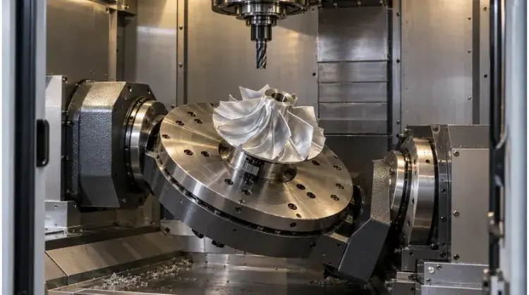
- Full 5-Axis (Simultaneous): All five axes move continuously. This is strictly required for sweeping 3D geometries where the tool must remain perfectly perpendicular to a contoured surface, such as aerospace impellers or medical implants.
- Tool Access Advantage: Because the part can tilt toward the spindle, the operator can use much shorter, stiffer cutting tools. A short tool deflects less, allowing for heavier cuts and yielding a mirror-like surface finish that deep-cavity 3-axis machining cannot achieve.
How to Choose CNC Machines for Your Parts?
Engineers and procurement teams should not select the machine; they should specify the requirements and let the factory route the part. However, understanding how a factory screens your drawing helps you design for the most cost-effective process.
Geometry and Tool Access
Look at the raw CAD file. Is the foundational shape a cylinder, a block, a flat sheet, or a bent profile? After identifying the base category, check for process-killers: perfectly sharp internal corners (requires EDM), extremely deep and narrow pockets (requires specialized long-reach tooling or EDM), or side-holes on a turned part (requires Mill-Turn).
Material and Workpiece Size
Confirm the material grade and stock form. A 500 mm aluminum bracket made from billet will route to a large VMC. If that same bracket is a cast iron raw blank, it will likely route to an HMC to manage the abrasive cast iron chips and heavy clamping requirements. Once a metal exceeds 45-50 HRC, traditional milling becomes uneconomical. While specialized “hard milling” with ceramic or CBN inserts can cut up to 60 HRC, these parts typically route to Grinding or EDM for reliable tolerances.
Tolerances and Production Volume
Identify the critical-to-function dimensions. A block with a general ±0.1 mm tolerance and a batch size of 10 routes to a standard 3-axis VMC. The exact same block with a ±0.01 mm true position requirement across three different faces routes to a 5-axis machine to eliminate re-fixturing errors, regardless of the batch size.
Initial Screening Matrix:
| Part Requirement | Candidate Process | Main Trade-Off | Information to Confirm |
| Multi-face features with tight relative tolerances | 5-Axis (3+2) Milling | Higher hourly rate, but eliminates fixture datum shift | Is the part geometry compatible with dovetail workholding? |
| Deep, narrow cavities in hardened tool steel | Sinker EDM | Zero mechanical cutting force, but extremely slow | Are multiple graphite electrodes required for roughing/finishing? |
| High-volume slender pins (L/D > 4:1) | Swiss-Type Lathe | High throughput, but requires expensive ground bar stock | Does the raw material meet the strict OD tolerance for the guide bushing? |
| Aluminum chassis with multiple tapped holes | Drill-Tap Center | Extremely fast cycle time, but lower rigidity for heavy milling | Do the required tap sizes match the machine’s spindle torque limits? |
How Machine Choice Affects Part Cost?
Assuming that a machine with a lower hourly rate automatically yields a cheaper part is a common procurement error. Total cost per part is driven by the distribution of setup time and handling.
Programming and Setup
NRE (Non-Recurring Engineering) includes CAM programming, designing custom soft jaws, loading tools, and indicating the part. A $300 setup cost spread across 5 prototypes adds $60 to each part. Spread across 5,000 production units, it adds $0.06. For low volumes, the goal is a machine that requires the simplest possible setup (like a 3-axis VMC with a standard vise).
Cycle Time and Automation
Cycle time includes cutting time, tool changes, and part loading. A standard lathe requires an operator to open the door, remove the part, load a new blank, and press start. A lathe equipped with a bar feeder runs continuously until the 3-meter bar is exhausted. The automated machine has a higher capital cost, but the “lights-out” cycle time drives the piece-price down significantly on high volumes.
Secondary Operations
If a waterjet cuts a part but leaves an edge taper that fails your tolerance block, the part must be moved to a mill to square the edge. Total cost must be evaluated across the complete routing chain: Cut -> Deburr -> Heat Treat -> Grind -> Plate.
Cost Comparison Case Study: 6-Sided Aluminum Optic Housing
- 3-Axis Route: Requires 4 separate vise setups. Total setup time: 1.5 hours. Total run time: 40 minutes. High risk of operator loading error on setups 3 and 4.
- 5-Axis Route: Requires 1 setup using a dovetail fixture. Total setup time: 20 minutes. Total run time: 35 minutes.
- Result: Even with the 5-axis machine’s hourly rate being 40% higher, the drastic reduction in setup and handling makes the 5-axis route cheaper per part at any batch size over 15 units.
Match your design to the right CNC technology. Submit your CAD files and tolerance requirements today. We will evaluate your geometry, identify the optimal machine routing, and return an actionable quote with a comprehensive DFM analysis.